AV TurboDock User manual

Important: Installation should be completed by a licensed,
qualied electrician. Installation must comply with the
provisions of the National Electric Code (NEC) and all
local codes. In cases of conict between local codes and
the NEC, local codes shall take precedence. Verify with
authority having jurisdiction.
Model TurboDock
NOTICE TO ELECTRICIAN: Leave this Installation Guide with the TurboDock
AeroVironment EV Solutions™ TurboDock™ Charging Station
INSTALLATION GUIDE
Wall-Mounted Installation

WALL-MOUNTED INSTALLATION
Detail of Wires
Hex nuts, #10-24
Hex nuts, #10-24
#10 Toothed lock washers
Wire-nuts
TurboDock Charge Module
Wall-mount enclosure cover
Ground wire assembly
Wall-mount back plate
#8-32 x ½” long
phillips-head screws
Thread-forming screws
Cable hanger
Black (L1)
Green (GND)
Red (L2 or Neutral)

4X
13
64
"
MOUNTING
HOLES
7
8
"
WIRING
HOLE
3"
3
7
16
"
6
1
4
"
2
1
8
"
1
1
2
"
TOP OF WALL
ENCLOSURE
TOP OF
PEDESTAL
C
L
C
L
HARDWARE PROVIDED IN WALL-MOUNT KIT
1 Qty - Wall-mount enclosure cover
1 Qty - Wall-mount back plate
1 Qty - Ground wire assembly
2 Qty - #8-32 x ½” long phillips-head screws
2 Qty - Hex nuts, #10-24
2 Qty - #10 Toothed lock washers
HARDWARE PROVIDED IN TURBODOCK KIT
4 Qty - Hex nuts, #10-24
1 Qty - Cable hanger
3 Qty - Thread-forming screws
3 Qty - Wire-nuts
SPECIAL TOOLS REQUIRED
13/64” drill bit for #10 screw clearance holes
7/8” drill bit or hole saw for wire entry hole
Drills as required for ¼” and #8 fasteners
Drill or knockout punch for conduit tting used
Magnetic torpedo level
1
3
16
"
2
3
4
"
13
32
"
MOUNTING
HOLES
C
L
C
L
BOTTOM OF
PEDESTAL
REQUIRED HARDWARE
**NOT SUPPLIED**
¼” Fasteners and/or anchors appropriate for wall
material and construction, Qty. 4
#8 fasteners and/or anchors appropriate for wall material
and construction, Qty. 3
Conduit and ttings as applicable
Wire, per local code, #12 AWG minimum, to extend to at
least 6” into wall mount enclosure
20A circuit breaker, double-pole or single-pole
TOOLS AND HARDWARE
Detail of template

1
2
3
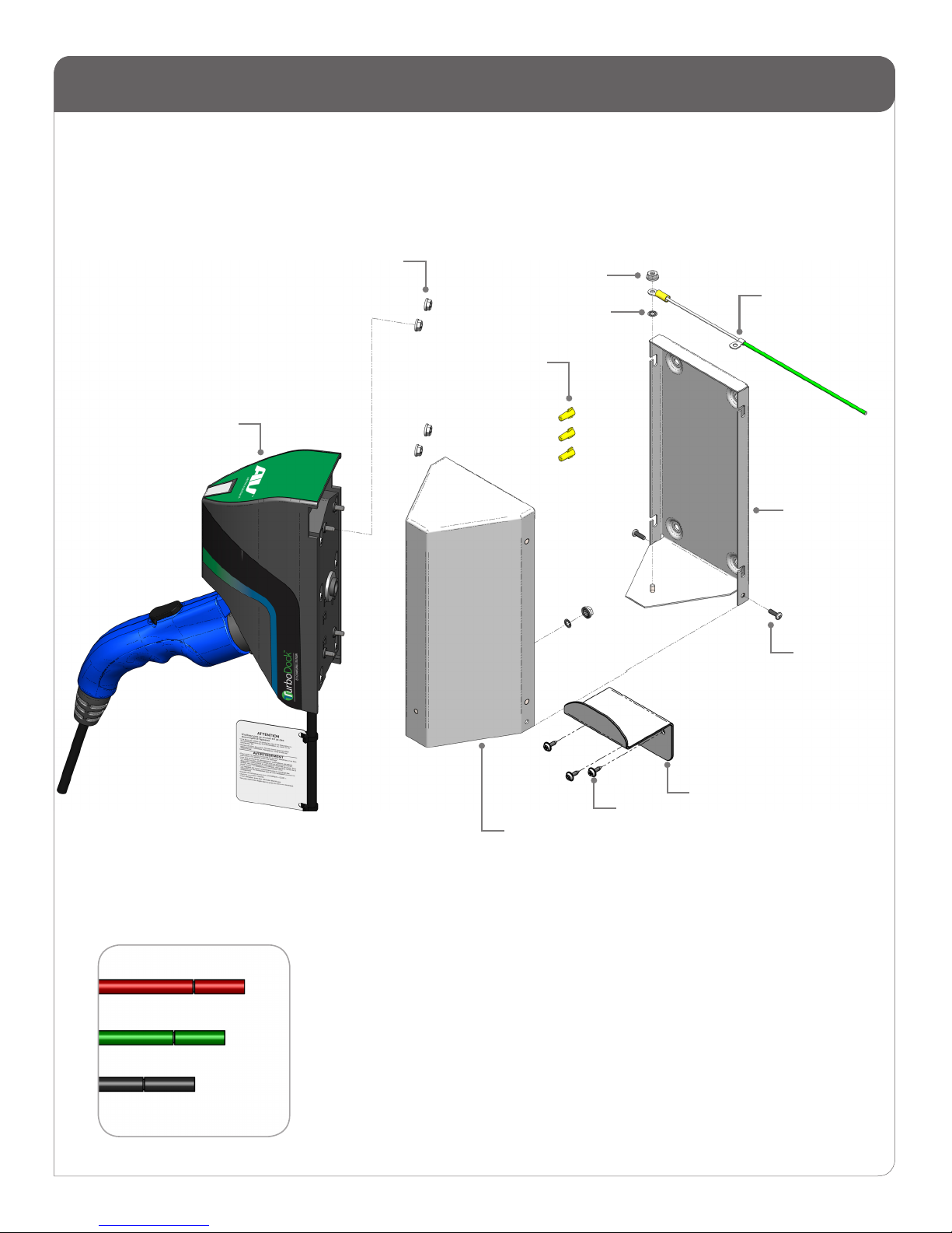
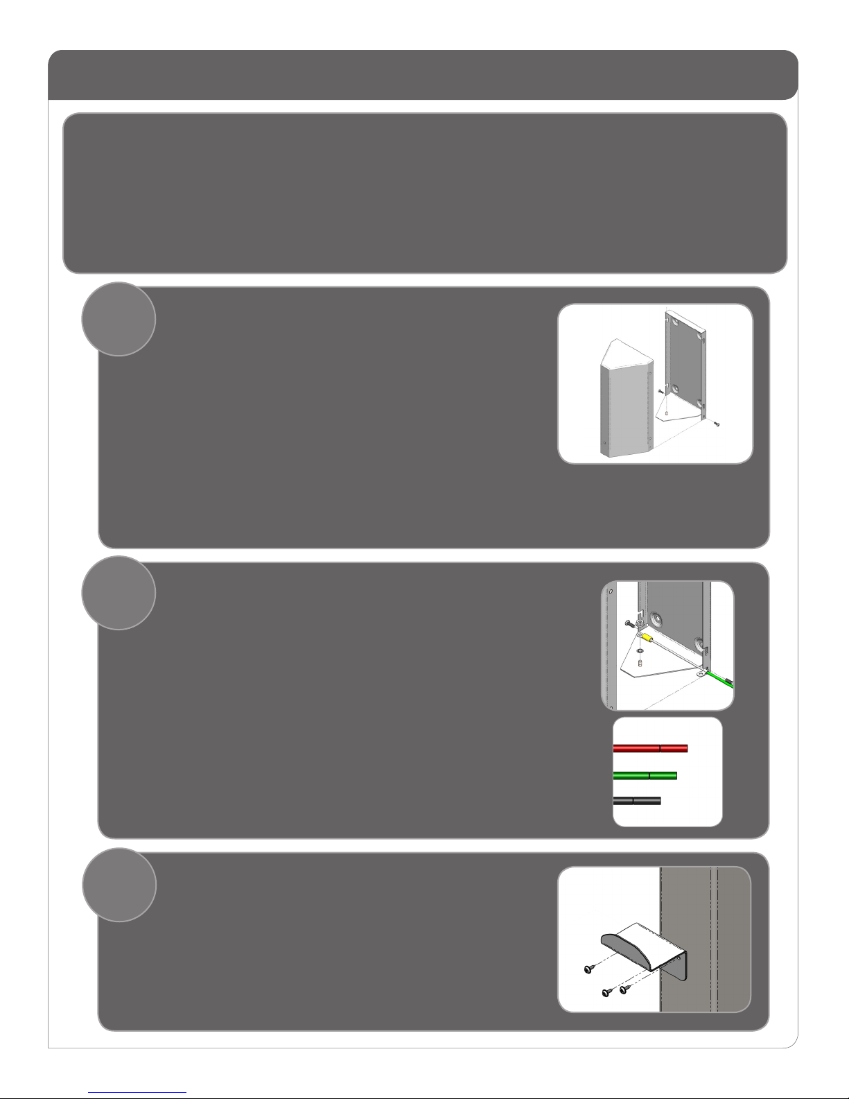
Connect the bonding wire from the enclosure back plate to the
front piece.
• Toothed lockwashers to be installed between housing and
ground lugs to ensure electrical contact.
Secure TurboDock wires to the electrical service wires using yellow
wire-nuts provided, as per electrical code.
Lift enclosure cover onto notches in back plate.
Replace #8 screws into holes at bottom sides of the enclosure.
Make your connections
Choose locations on the wall for the cable hangers. Using a cable
hanger as a template, mark the holes for the hangers.
• Holes must be at least 6” from the bottom of TurboDock.
• Leave enough room between hangers for cables to hang freely.
• Attach the cable hangers with installer-supplied #8 fasteners.
INSTALLATION STEPS
Before you start:
Wall Mount set up
Black (L1)
Green (GND)
Red (L2 or Neutral)
• Determine the location and orientation of the wall mounted TurboDock(s), as directed by Account
Manager (AM). Decide how high the mount must be.**
• **Installation must comply with the Americans with Disabilities Act (ADA). The top of each
TurboDock charger must be between 39” and 49” above the access surface. Access space be-
tween and around the wall-mounts must also comply with the ADA.
• Run the appropriate conduit and wiring from the service panel to the installation site per local
code, #12 AWG minimum. Use a 20 Amp double-pole circuit breaker for 240V service (Level II
charging) or a 20 Amp single-pole circuit breaker for 120V service (Level I charging).
Open the wall-mount enclosure. Using the back plate as a template,
mark hole locations on wall.
• Plumb the back plate with level.
• Do not secure back plate to wall yet.
Drill or punch a conduit tting hole in either the bottom or back
of the mounting plate, as appropriate for the orientation of the
conduit inlet.
Drill holes in the enclosure front piece:
• Use template included with TurboDock to mark the 5 holes
for each TurboDock on each face of the wall mount enclosure
where a TurboDock will be installed.
• Note reference line to be aligned with top of wall mount
enclosure.
Attach TurboDock chargers to enclosure:
• Insert the 3 wires through large hole in the side of the enclosure.
• Insert the studs on the charger into the 13/64” holes on the
enclosure.
• Install and securely tighten the four #10-24 nuts provided.
• Repeat for other charger if a dual installation.
Attach the Hanger

Complete install
4Test each charger:
• Turn on power (to one unit at a time, if possible).
• Verify that top light is steady blue, otherwise refer to the
troubleshooting guide.
• Verify that lower-front lights show steady blue, otherwise refer to
the troubleshooting guide.
• On the nameplate label on the front of each TurboDock, mark the
correct box: 240V or 120V.
Inform the Account Manager that the TurboDock is ready with "open
access". If the AM desires, you can now test the TurboDock by
charging a vehicle.
INSTALLATION STEPS

Customer Support:
1-888-833-2148
20254-76
CORPORATE HEADQUARTERS
AeroVironment, Inc.
ev@avinc.com ● www.evsolutions.com © 2014 AeroVironment, Inc. All rights reserved.
AeroVironment, TurboDock, EV Solutions, and the AeroVironment logo are trademarks of AeroVironment, Inc.
Corporate names, trademarks, registered trademarks, service marks, symbols, and logos stated herein are property of their
respective companies.
Specications are subject to change without notice. Images of the Charging Station Model TurboDock are representative;
production models may vary.
No portion of these materials may be duplicated, used or disclosed without prior written permission from AeroVironment, Inc.
Disclaimer: This Installation Guide includes the latest information available at the time of printing. AeroVironment, Inc.
reserves the right to make changes to this user guide and/or product without further notice. Changes or modications to this
product not completed by an authorized service provider could void the product warranty.
Other manuals for TurboDock
1
Table of contents
Other AV Batteries Charger manuals