Ava bqt YD38L User manual
INSTALLATION AND OPERATING INSTRUCTIONS
Solenoid Dropbolt YD38L
Page 2
NOTICES
Please ensure you read all instructions!
WARNING - Live parts inside.
WARNING - The handling and installation of this device is recommended for a professional.
WARNING - Use of an unsuitable power supply unit may cause product failure or injury.
WARNING - Do not remove cover while device is live.
WARNING - Ensure installation does not expose sharp edges of the product to users.
This device complies with Part 15 of the FCC Rules. Operation is subject to the following two conditions:
1. This device may not cause harmful interference.
2. This device must accept any interference received, including interference that may cause undesired
operation.
Note: This equipment has been tested and found to comply with the limits for a Class A digital device,
pursuant to Part 15 of the FCC Rules. These limits are designed to provide reasonable protection against
harmful interference when the equipment is operated in a commercial environment. This equipment
generates, uses, and can radiate radio frequency energy and, if not installed and used in accordance
with the instruction manual, may cause harmful interference to radio communications. Operation of this
equipment in a residential area is likely to cause harmful interference in which case the user will be
required to correct the interference at their own expense.
Modifications: Any modifications made to this device that are not approved by the manufacturer may
void the authority granted to the user by the FCC to operate this equipment.
This product is carrying the CE Mark in accordance with the related European Directives. Responsible
for CE Marking is,
BQT Solutions (SEA) Pte. Limited
41B Neil Road, #03-01,
Singapore, 088824
The complete EU Declaration of Conformity is available at www.bqtsolutions.com
In the European Union, Norway, Iceland and Liechtenstein: This symbol on the product, or in the
manual and in the warranty, and/or on its packaging indicates that this product shall not be treated as
household waste. Instead it should be taken to an applicable collection point for the recycling of electrical
and electronic equipment.
By ensuring this product is disposed of correctly, you will help to prevent potential negativeconsequences
to the environment and human health, which could otherwise be caused by inappropriate handling of this
product.
In Countries Outside the European Union, Norway, Iceland and Liechtenstein: If you wish to dispose
of this product please contact your local authorities and ask for the correct way of disposal.
© 2019 BQT Solutions (SEA) Pte. Limited. All rights reserved.
BQT Solutions (SEA) Pte Limited will not be liable for any direct, indirect, incidental or consequential loss or
damage in any way related to this product. BQT Solutions (SEA) Pte Limited reserves the right to upgrade or
change this product or instruction manual without prior notice. BQT Solutions (SEA) Pte Limited assumes no
liability for damages incurred directly or indirectly from errors, omissions or discrepancies between the product
and the manual.
The YD38L is designed by BQT Solutions (SEA) Pte. Limited and manufactured by BQT Solutions (NZ)
Limited in New Zealand.
For more information and contact details please visit,
www.bqtsolutions.com

Page 3
CONTENTS
1. DESCRIPTION.........................................................................................................................................................4
2. PRODUCT UNBOXED ............................................................................................................................................4
3. DIMENSIONS ..........................................................................................................................................................4
3.1. LOCK...................................................................................................................................................................4
3.2. STRIKE PLATE .....................................................................................................................................................5
3.3. HOUSING.............................................................................................................................................................5
3.4. DRESS PLATE......................................................................................................................................................5
4. PRE-INSTALLATION ASSESSMENT....................................................................................................................5
4.1. MECHANICAL .......................................................................................................................................................5
4.2. ELECTRICAL.........................................................................................................................................................6
5. INSTALLATION.......................................................................................................................................................6
5.1. MORTISE INSTALLATION........................................................................................................................................6
5.2. SURFACE INSTALLATION.......................................................................................................................................8
6. WIRING..................................................................................................................................................................10
6.1. THREE WIRE CONNECTION..................................................................................................................................10
6.2. TWO WIRE CONNECTION.....................................................................................................................................10
6.3. MONITORS.........................................................................................................................................................10
6.4. DIP SWITCH POSITIONS.......................................................................................................................................11
7. OPERATION..........................................................................................................................................................11
7.1. THREE WIRE MODE (RECOMMENDED)..................................................................................................................11
7.2. TWO WIRE MODE................................................................................................................................................11
8. SPECIFICATIONS.................................................................................................................................................12
9. MAINTENANCE AND INSPECTION.....................................................................................................................12
Page 4
1. DESCRIPTION
The YD38L is a heavy duty magnetically latching solenoid operated dead bolting lock suited for commercial or
residential doors. Its dual action reduces alignment problems as the integrated magnetic latch captures the door
before the deadbolt secures it making the YD38L ideally suited for swing through doors. It is supplied with a matching
strike plate and can be surface mounted with the aid of accessories or installed into a mortise for a concealed
solution.
Integrated electronics provide complete control over the lock and offer an array of features;
Multi–voltage input (12-24VDC)
Multiple locking / unlocking attempts
Adjustable timed re-lock
Current reduction circuitry
Door position and bolt position monitors
High physical strength –10,000N
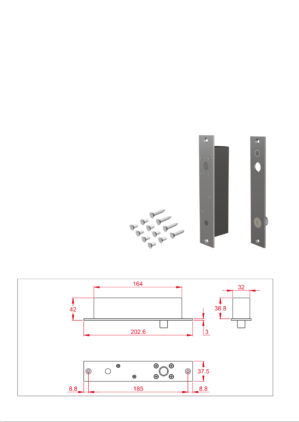
2. PRODUCT UNBOXED
The YD38L is supplied with four 10G x 1” csk. self-tapping
screws for fitting the lock and strike plate. They are
suitable for mounting in both aluminium and wooden doors
and frames. Also included are eight M5 x 10 Machine
Screws.
The mounting holes in the locks face plate and strike plate
are ø 5.2mm so any 10G or 5mm screw can be used.
3. DIMENSIONS
The dimensions shown (in millimetres) are approximate and are subject to change without prior notice.
3.1. Lock
Mounting Screws
Lock
Strike Plate

Page 5
3.2. Strike Plate
3.3. Housing
Available separately
3.4. Dress Plate
Available separately
4. PRE-INSTALLATION ASSESSMENT
4.1. Mechanical
The first decision regarding installation is whether the YD38L will be mortised or surface mounted to the door / door
frame. Mortise installation ensures a discrete solution as the lock and strike plate can be embedded into the door
and frame, however in some instances this is not possible. Glass doors for example require surface mounting the
lock which is done with the aid of the YD38L housing.
Whichever method is chosen it is important that the lock and strike plate are aligned correctly. This is achieved when
the top of the lock face plate aligns with the top of the strike plate. It is also important that when the door is closed
the gap between the lock and strike plate does not exceed 6mm otherwise the lock will not sense the strikes position
resulting in incorrect operation.

Page 6
The YD38L can be installed vertically or horizontally but is not designed to be mounted in a floor cavity firing
upwards or in a wet environment.
4.2. Electrical
The first consideration is to establish where to run the wires and decide on what feedback is required from the lock.
There are a total of eight available connections and for a fully featured lock it is compulsory to connect three with the
other five providing feedback. Alternatively the lock does operate with reduced features on two compulsory
connections and five optional.
The three essential connections are; Positive (+), Negative (-) and Control (CL). The five optional connections provide
feedback about the lock status; Door Position and Bolt Position. If desired, wires can be run from these connections
to integrate into access control or alarm systems to provide full monitoring.
Finally the correct gauge of wire needs to be chosen as when connecting the power wires (+ and -) to the lock,
voltage drop across these wires can limit the lock operation. For all the remaining connections, a lower gauge wire
can be used as these are only signal wires.
The following chart shows the appropriate wire gauge for a range of distances between the lock and power supply
assuming the voltage measured at the lock is within the range of 12-24VDC ±10%.
AWG
AREA (MM2)
MAXIMUM DISTANCE (M)
12VDC
24VDC
24
0.20
10
30
22
0.33
16
48
20
0.52
26
77
18
0.82
41
122
16
1.31
65
195
14
2.08
103
310
5. INSTALLATION
Two installation examples are detailed on the following pages however any combination of mortise and surface
mounting can be achieved. Whichever installation method is chosen it is vital to ensure that the lock face plate and
the strike plate align correctly and the gap between the locks face plate and the strike plate does not exceed 6mm
when the door is closed.
5.1. Mortise installation
A typical mortise installation is described with the lock fitted into the door frame while the strike plate is secured to
the door. It is possible to install the lock into the door and the strike plate to the frame however running the wiring to
the lock can be difficult.

Page 7
5.1.1. Cutting the mortises
Using the supplied lock dimensions a mortise
is cut in the door frame that is suitable to
house the lock. An appropriate sized mortise
is then cut for the strike plate and holes to
house the magnetic catch and to accept the
lock pin is drilled. The lock pin hole behind
the strike plate needs to be free from debris
and deep enough to allow the lock pin to fully
extend when locked.
5.1.2. Wiring the lock
Wires are run outfrom the back of the mortise
and following the connection guide on the
locks cover, connected to the lock.
Detailed wiring information can be found in
Section 6 - Wiring.
5.1.3. Fitting the lock and strike plate
The lock is slid back into the mortise, making
sure that the wiring integrity is maintained,
and secure with the supplied mounting
screws. Likewise the strike plate is fitted into
its mortise and secured in place.

Page 8
5.1.4. Checking the operation
With the lock and strike installed and the
wiring complete the door is closed to check
alignment and operation. The magnetic latch
should ‘capture’ the door and align it correctly
so the lock pin can extend through the hole
in the strike plate and door, to achieve
locking.
5.2. Surface installation
By using a YD38L housing the lock and or strike plate can be secured to the door or door frame eliminating the need
for cutting mortises. Housings are available with adhesive tape supplied for easy application to glass doors in addition
to having screw hole mounting points for wood and metal doors.
5.2.1. Securing the housing to wood
Two 10G x 1” hex head self-tapping screws are
supplied with the housing and can be screwed
into the wood door frame. The housing has two
keyhole cut outs that fit over the screw heads
and once the housing is in place the screws can
be tightened with a spanner.
5.2.2. Wiring the lock
The wires will need to be run into the housing to
connect to the lock. The position of the hole is
determined at installation time by finding exactly
where the wiring will enter the housing, and drill
an 8mm hole through the housing wall. The
housing is supplied with one grommet, which
can be pushed into the drilled hole to protect the
wires form the sharp edge of the hole.
Detailed wiring information can be found in
Section 6 - Wiring.

Page 9
5.2.3. Fitting the lock
Once wired, the lock is slid into the housing and
secured in place with the M5 X 10 csk screws
that were supplied with the lock.
5.2.4. Securing the housing to glass
For simple application to glass the YD38L
housings are supplied with self-adhesive tape.
With the backing removed the housing can be
applied directly to the glass. A flat stainless steel
dress plate is fitted on the opposite of the glass
to give a clean finish.
5.2.5. Fitting the strike plate
The strike plate is placed into the housing and
secured in place with the M5 x 10 csk screws
that were supplied with the lock.
5.2.6. Checking the operation
With the lock and strike installed and the wiring
complete the door is closed to check alignment
and operation. The magnetic latch should
‘capture’ the door and align it correctly so the
lock pin can extend through the hole in the strike
plate and door, to achieve locking.

Page 10
6. WIRING
The YD38L is fitted with eight connectors; five are optional and provide monitoring of the lock pin and door positions.
Control of the lock is achieved by using the remaining three wires however a reduced function two wire mode is
available if desired. Connect the YD38L as per the following chart.
+
1
Power
Positive connection to DC power supply (12 –24V)
CL
2
Switched positive control input
-
3
Negative connection to DC power supply (12 –24V)
C
4
Door Position Switch
Common contact of the door position monitor
NO
5
Normally open contact of the door position monitor
C
6
Bolt Position Switch
Common contact of the bolt position monitor
NO
7
Normally open contact of the bolt position monitor
NC
8
Normally closed contact of the bolt position monitor
6.1. Three wire connection
The three wire mode requires a continuous
connection of power to terminals 1 (+ve) and 3 (-ve).
Wiring the lock for fail safe or fail secure configurations
is identical.
6.2. Two wire connection
The two wire mode differs between fail safe and fail secure configurations but both require a switched power supply
connected to terminals ‘1’ and ‘3’. In addition, for fail safe configuration the dip switch needs to be repositioned as
shown in Section 6.4 - Dip switch positions. Wire links (not supplied) are connected from terminals ‘2’ to ‘4’ and ‘1’
to ‘5’ for fail safe. A wire link is connected between terminals ‘1’ and ‘2’ for fail secure.
Fail Safe Fail Secure
6.3. Monitors
The five monitor connectors found on the YD38L are available to provide door and bolt position feedback. If desired
wires can be run from these connections to integrate with access control or alarm systems to provide full monitoring.
When a two wire fail safe operation is chosen the door position monitor is not available.
The monitor switches are optional
connections
The power and control (CL)
wires must be permanently
connected
Switched power supply
permanently connected
The bolt position switch is an optional
connection
The monitor switches are optional
connections
Switched power supply
permanently connected
Page 11
6.4. Dip switch positions
In addition to running the necessary wires for the desired mode, positioning the three dip switches located on the
lock printed circuit board determines the operation. These are accessed by removing the cover.
MARKINGS S1, S2 AND M ARE FOUND ON THE PRINTED CIRCUIT BOARD.
Switches S1 and S2 are used to set the timed re-lock. If an unlock signal is given to the lock but the door is not
opened the YD38L can automatically lock itself again after a selected time. This ensures that a door cannot be left
unsecured if it has been unlocked but not opened. The timer is factory set to 9 seconds but 0, 3 and 6 second options
are offered and selected by positioning the dip switches accordingly.
Switch M is used to select fail safe or fail secure mode. This is factory set as ordered and the only time it will
need to be moved is when operating a fail-safe lock in the two wire mode.
TIMED RELOCK
0 second
3 second
6 second
9 seconds - default
SWITCH POSITIONS
S1 On & S2 On
S1 Off & S2 On
S1 On & S2 Off
S1 Off & S2 Off
MODE
Fail Safe
Fail Secure
3 WIRE MODE
M Off
M On
2 WIRE MODE
M On
M On
7. OPERATION
7.1. Three wire mode (Recommended)
In either fail safe or fail secure configuration, maintained connection of ‘1’ to ‘2’ will keep the YD38L unlocked
regardless of the door position. The following scenarios assume that the control signal is open at the start of the
operation sequence as a maintained connection will cause the lock to stay unlocked indefinitely.
7.1.1. Fail safe operation
Assume the door is closed and locked. Momentarily connecting ‘1’ and ‘2’ unlocks the door for a period of 9 seconds*.
After the 9 seconds has elapsed if the door has not been opened the YD38L automatically locks again. If the door
has opened within the 9 second window (which is the case in normal operation) the timed re-lock is overridden and
automatic relocking occurs as soon as the door is closed. On closing, full power is applied to the YD38L 9 times in
15 seconds before the current is reduced and the lock goes into a holding mode to minimize heating and power
consumption. The YD38L will remain unlocked as long as the door is open.
7.1.2. Fail secure operation
Assume the door is closed and locked. Momentarily connecting ‘1’ and ‘2’ unlocks the door and over a 9 second
period full power is applied to the lock 5 times. If the door remains closed, after 9 seconds* has elapsed the YD38L
automatically locks again. If the door has opened within the 9 second window (which is the case in normal operation)
the YD38L will remain unlocked and in a holding mode until the door is closed again and automatic re-locking occurs.
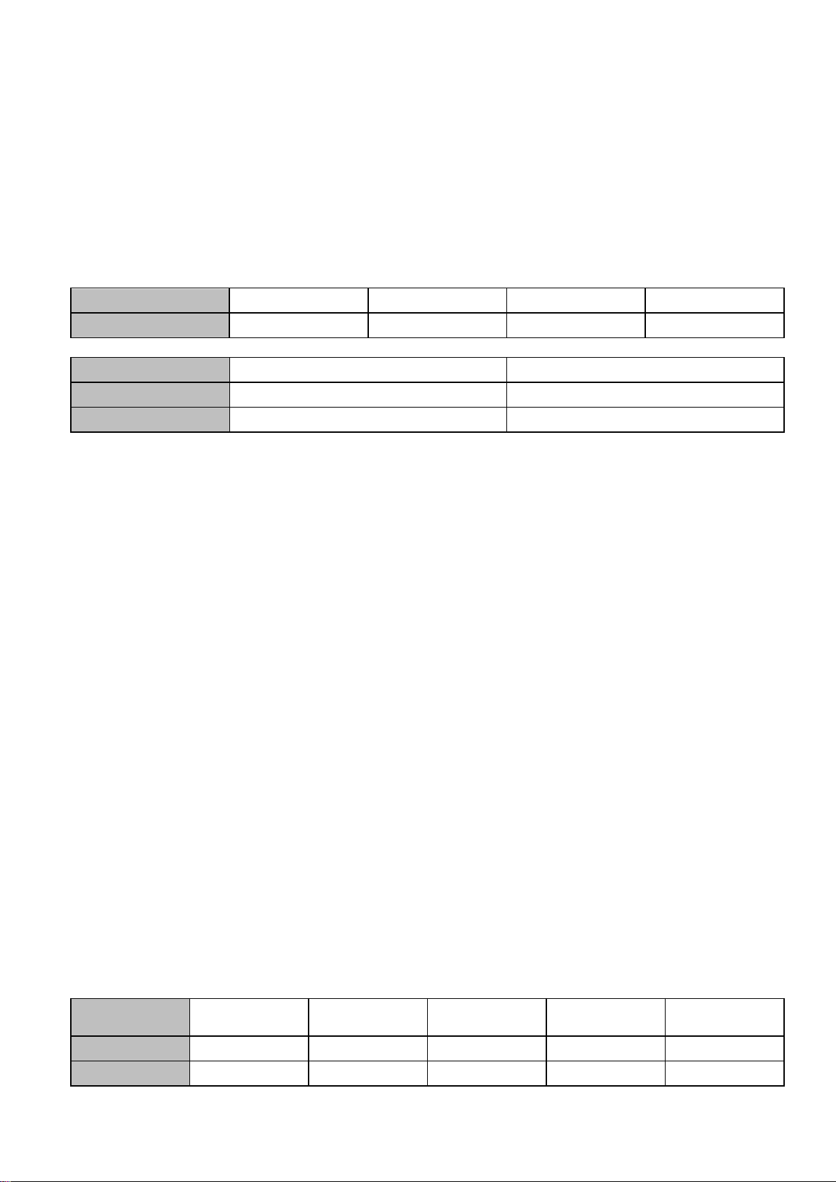
7.2. Two wire mode
In installations where running three wires to the lock is not possible or desired the YD38L can operate effectively on
two wires. Although the functions are reduced, as seen in the table below, controlling the lock this way still offers a
high security locking solution.
FEATURES
Multiple re-lock
(fail safe)
Multiple unlock
(fail secure)
Auto re-lock
Anti-Tamper
Adjustable timed
re-lock
3 WIRE MODE
Yes 9x
Yes 5x
Yes
Yes
Yes
2 WIRE MODE
Yes 5x
Yes 5x
Fail safe only
Yes
No

Page 12
8. SPECIFICATIONS
MATERIALS
Bolt Pin
Stainless Steel (SS304), ø14.2mm, 14mm Extension
Lock / Strike Plate
Stainless Steel (SS304), 3mm Thick
MECHANICAL
Cycle life
1,000,000
Max Strike Gap
6mm
Holding Force
20,000N (2000kg)
ELECTRICAL
Voltage at Lock
12 –24VDC ±15%
Current Usage
Max Holding Current
230mA@12V
90mA@24V
Max Operating Current
1500mA@12V
1400mA@24V
Monitor Switches
Bolt position –25VDC, 0.5A
Door position –100VDC, 0.5A
CERTIFICATIONS
CE
EMC 2014/30/EU
EN 61000-6-1:2007
EN 61000-6-3:2007+A1:2011
RoHS 2011/65/EU
RoHS 2 Compliant
MD 2006/42/EC
EN ISO 12100:2010
9. MAINTENANCE AND INSPECTION
The YD38L has been lubricated at assembly and applying any other type of lubricant may void the warranty. With
the cover removed it is important to take care when selecting the dip switch positions. A dry cloth can be used to
polish the stainless steel face plate and strike plate as required. This lock contains components that are subject to
wear based on usage, doorway operation and installation; all such factors are beyond the control and measurement
of the manufacturer. The lock may be vulnerable and subject to failure as a consequence of wear and as its
components near the end of the period of normal usage.
It is the responsibility of the owner/end-user to:
a) Ensure that the lock is installed in accordance with the instructions set out in these guidelines.
b) Determine the suitability of this lock for the application intended and in particular when using this lock in
critical applications such as on fire, high security, safety, or emergency exit doors.
c) Regularly inspect this lock in order to assess signs of wear and tear, and determine if the operation still
conforms to the instructions set out in these guidelines.
d) Regularly inspect the lock and evaluate cycle life.
e) Determine when this lock should be replaced.
MP001254.003
Table of contents
Other Ava Door Lock manuals


Popular Door Lock manuals by other brands

Ingersoll-Rand
Ingersoll-Rand Schlage F Series quick start guide

Allegion
Allegion SCHLAGE Element Series installation instructions

Lockly
Lockly SECURE PRO installation guide

Onward
Onward 1463658 Instructions for Installation or Replacement

IDTECK
IDTECK Star 100W user manual

ENTRO
ENTRO A6000 installation instructions

Glutz
Glutz PIATTO Fixing instructions

Assa Abloy
Assa Abloy Yale Assure Lock YRC256-ZW3 Installation and programming instructions

DITEC
DITEC DAS802LOK installation manual

Hans Grohe
Hans Grohe PuraVida Instructions for use/assembly instructions

BANKSTON
BANKSTON Plate Euro Set Install instructions

Yale
Yale Conexis L1 manual


