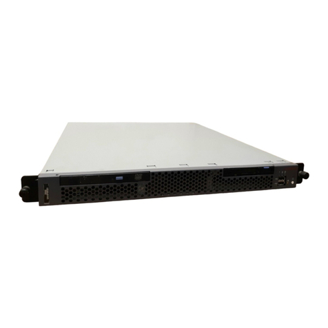
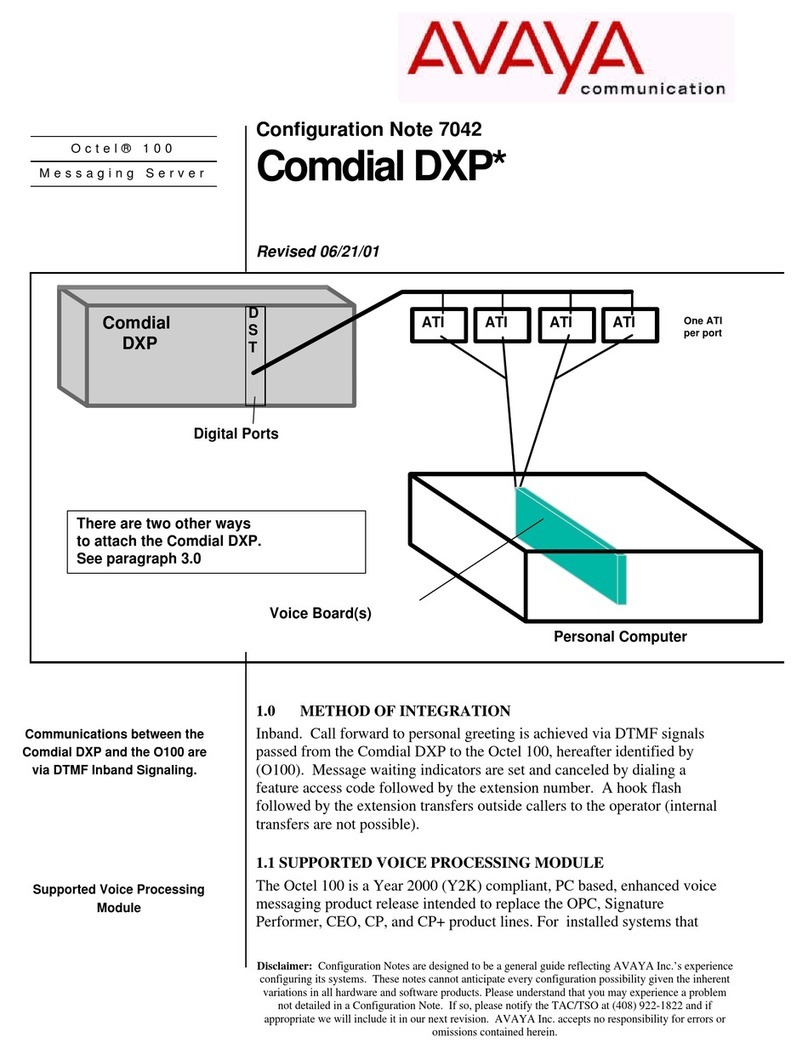
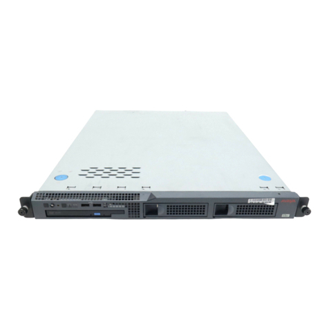
Avaya 1000 Series Service manual

Circuit Card Reference
Nortel Communication Server 1000
7.0
NN43001-311, 04.04
July 2011

©2011 Avaya Inc.
All Rights Reserved.
Notice
While reasonable efforts have been made to ensure that the
information in this document is complete and accurate at the time of
printing,Avaya assumes no liability for any errors.Avaya reserves the
right to make changes and corrections to the information in this
document without the obligation to notify any person or organization of
such changes.
Documentation disclaimer
“Documentation” means information published by Avaya in varying
mediumswhichmayincludeproductinformation,operatinginstructions
and performance specifications that Avaya generally makes available
to users of its products. Documentation does not include marketing
materials. Avaya shall not be responsible for any modifications,
additions, or deletions to the original published version of
documentation unless such modifications, additions, or deletions were
performed byAvaya. End User agrees to indemnify and hold harmless
Avaya,Avaya's agents, servants and employees against all claims,
lawsuits, demands and judgments arising out of, or in connection with,
subsequentmodifications,additionsordeletions tothisdocumentation,
to the extent made by End User.
Link disclaimer
Avaya is not responsible for the contents or reliability of any linked Web
sites referenced within this site or documentation provided by Avaya.
Avaya is not responsible for the accuracy of any information, statement
or content provided on these sites and does not necessarily endorse
the products, services, or information described or offered within them.
Avayadoesnotguaranteethattheselinkswillworkallthetimeandhas
no control over the availability of the linked pages.
Warranty
Avaya provides a limited warranty on its Hardware and Software
(“Product(s)”). Refer to your sales agreement to establish the terms of
the limited warranty. In addition, Avaya’s standard warranty language,
as well as information regarding support for this Product while under
warranty is available toAvaya customers and other parties through the
Avaya Support Web site: http://support.avaya.com. Please note that if
you acquired the Product(s) from an authorizedAvaya reseller outside
of the United States and Canada, the warranty is provided to you by
said Avaya reseller and not by Avaya.
Licenses
THE SOFTWARE LICENSE TERMSAVAILABLE ON THEAVAYA
WEBSITE, HTTP://SUPPORT.AVAYA.COM/LICENSEINFO/ ARE
APPLICABLE TOANYONE WHO DOWNLOADS, USES AND/OR
INSTALLS AVAYA SOFTWARE, PURCHASED FROM AVAYA INC.,
ANY AVAYAAFFILIATE, OR AN AUTHORIZED AVAYA RESELLER
(AS APPLICABLE) UNDER A COMMERCIAL AGREEMENT WITH
AVAYA OR AN AUTHORIZED AVAYA RESELLER. UNLESS
OTHERWISE AGREED TO BY AVAYA IN WRITING, AVAYA DOES
NOT EXTEND THIS LICENSE IF THE SOFTWARE WAS OBTAINED
FROMANYONEOTHERTHANAVAYA,ANAVAYAAFFILIATEORAN
AVAYAAUTHORIZED RESELLER; AVAYA RESERVES THE RIGHT
TO TAKE LEGALACTION AGAINST YOU AND ANYONE ELSE
USING OR SELLING THE SOFTWARE WITHOUT A LICENSE. BY
INSTALLING, DOWNLOADING OR USING THE SOFTWARE, OR
AUTHORIZING OTHERS TO DO SO, YOU, ON BEHALF OF
YOURSELFAND THE ENTITYFOR WHOM YOUARE INSTALLING,
DOWNLOADING OR USING THE SOFTWARE (HEREINAFTER
REFERRED TO INTERCHANGEABLYAS “YOU” AND “END USER”),
AGREE TO THESE TERMSAND CONDITIONS AND CREATE A
BINDING CONTRACT BETWEEN YOU ANDAVAYA INC. OR THE
APPLICABLE AVAYAAFFILIATE ( “AVAYA”).
Copyright
Except where expressly stated otherwise, no use should be made of
materials on this site, the Documentation, Software, or Hardware
provided byAvaya.All content on this site, the documentation and the
Product provided by Avaya including the selection, arrangement and
design of the content is owned either by Avaya or its licensors and is
protectedbycopyright and otherintellectualpropertylaws includingthe
sui generis rights relating to the protection of databases. You may not
modify, copy, reproduce, republish, upload, post, transmit or distribute
in any way any content, in whole or in part, including any code and
software unless expressly authorized by Avaya. Unauthorized
reproduction, transmission, dissemination, storage, and or use without
the express written consent of Avaya can be a criminal, as well as a
civil offense under the applicable law.
Third-party components
Certain software programs or portions thereof included in the Product
may contain software distributed under third party agreements (“Third
Party Components”), which may contain terms that expand or limit
rights to use certain portions of the Product (“Third Party Terms”).
Information regarding distributed Linux OS source code (for those
Products that have distributed the Linux OS source code), and
identifyingthecopyright holdersoftheThirdPartyComponents andthe
Third Party Terms that apply to them is available on theAvaya Support
Web site: http://support.avaya.com/Copyright.
Preventing Toll Fraud
“Toll fraud” is the unauthorized use of your telecommunications system
by an unauthorized party (for example, a person who is not a corporate
employee, agent, subcontractor, or is not working on your company's
behalf). Be aware that there can be a risk of Toll Fraud associated with
your system and that, if Toll Fraud occurs, it can result in substantial
additional charges for your telecommunications services.
Avaya Toll Fraud Intervention
If you suspect that you are being victimized by Toll Fraud and you need
technical assistance or support, call Technical Service Center Toll
Fraud Intervention Hotline at +1-800-643-2353 for the United States
andCanada.Foradditionalsupporttelephone numbers, see theAvaya
Support Web site: http://support.avaya.com. Suspected security
vulnerabilities with Avaya products should be reported to Avaya by
Trademarks
The trademarks, logos and service marks (“Marks”) displayed in this
site, the Documentation and Product(s) provided by Avaya are the
registered or unregistered Marks of Avaya, its affiliates, or other third
parties. Users are not permitted to use such Marks without prior written
consent from Avaya or such third party which may own the Mark.
Nothing contained in this site, the Documentation and Product(s)
shouldbeconstrued as granting,byimplication,estoppel, orotherwise,
any license or right in and to the Marks without the express written
permission of Avaya or the applicable third party.
Avaya is a registered trademark ofAvaya Inc.
All non-Avaya trademarks are the property of their respective owners,
and “Linux” is a registered trademark of Linus Torvalds.
Downloading Documentation
For the most current versions of Documentation, see the Avaya
Support Web site: http://support.avaya.com.
Contact Avaya Support
Avaya provides a telephone number for you to use to report problems
or to ask questions about your Product. The support telephone number
is 1-800-242-2121 in the United States. For additional support
telephonenumbers,seetheAvayaWebsite: http://support.avaya.com.
2 Circuit Card Reference July 2011
Comments? [email protected]

Contents
Chapter 1: New in this release........................................................................................... 21
Features.................................................................................................................................................... 21
Common Processor Media Gateway (CP MG) card........................................................................ 21
Common Processor Dual Core (CP DC) card.................................................................................. 21
128-port DSP daughterboard........................................................................................................... 22
Other......................................................................................................................................................... 22
Revision History............................................................................................................................... 22
Chapter 2: How to get help................................................................................................. 25
Getting help from the Nortel web site........................................................................................................ 25
Getting help over the telephone from a Nortel Solutions Center.............................................................. 25
Getting help from a specialist by using an Express Routing Code........................................................... 26
Getting help through a Nortel distributor or reseller.................................................................................. 26
Chapter 3: Introduction...................................................................................................... 27
Subject...................................................................................................................................................... 27
Note on legacy products and releases............................................................................................. 27
Applicable systems................................................................................................................................... 27
System migration...................................................................................................................................... 27
Intended audience.................................................................................................................................... 28
Conventions.............................................................................................................................................. 28
Terminology...................................................................................................................................... 28
Related information................................................................................................................................... 29
Technical documentation.................................................................................................................. 29
Online............................................................................................................................................... 29
CD-ROM........................................................................................................................................... 29
Chapter 4: Overview........................................................................................................... 31
Contents.................................................................................................................................................... 31
Line cards.................................................................................................................................................. 32
NT1R20 Off-Premise StationAnalog Line card................................................................................ 32
NT5D11 and NT5D14 Lineside T1 interface card............................................................................. 33
NT5D33 and NT5D34 Lineside E1 Interface card............................................................................ 33
NT8D02 Digital Line card................................................................................................................. 33
NT8D09 analog message waiting line card...................................................................................... 33
Analog line interface units................................................................................................................ 39
Digital line interface units................................................................................................................. 41
Analog line call operation................................................................................................................. 43
Digital line call operation.................................................................................................................. 46
Lineside T1 and E1 call operation.................................................................................................... 47
Voice frequency audio level.............................................................................................................. 55
Off-premise line protection............................................................................................................... 55
Line protectors.................................................................................................................................. 56
Line protection grounding................................................................................................................. 56
Line and telephone components...................................................................................................... 57
Trunk cards............................................................................................................................................... 57
NT8D14 Universal Trunk card.......................................................................................................... 58
Circuit Card Reference July 2011 3

NT8D15 E and M Trunk card............................................................................................................ 58
NTCK16 Generic Central Office Trunk card..................................................................................... 58
Installation........................................................................................................................................ 59
Operation.......................................................................................................................................... 60
Host interface bus............................................................................................................................ 60
Trunk interface unit........................................................................................................................... 65
Serial Data Interface (SDI) cards.............................................................................................................. 66
Uses................................................................................................................................................. 67
Features........................................................................................................................................... 67
Specifications................................................................................................................................... 68
Installation........................................................................................................................................ 69
Maintenance..................................................................................................................................... 69
Chapter 5: Circuit card installation................................................................................... 71
Contents.................................................................................................................................................... 71
Card slots - Large System......................................................................................................................... 71
Circuit and installation............................................................................................................................... 71
Precautions............................................................................................................................................... 74
Installing a circuit card............................................................................................................................... 76
Chapter 6: Acceptance tests.............................................................................................. 79
Contents.................................................................................................................................................... 79
Introduction............................................................................................................................................... 79
Conference cards...................................................................................................................................... 79
Digitone receiver cards............................................................................................................................. 81
Line cards.................................................................................................................................................. 82
Multifrequency sender cards..................................................................................................................... 82
Multifrequency signaling cards.................................................................................................................. 83
Network cards........................................................................................................................................... 83
Trunk cards............................................................................................................................................... 84
Tone and digit switch cards....................................................................................................................... 85
Chapter 7: Option settings................................................................................................. 87
Contents.................................................................................................................................................... 87
Circuit card grid......................................................................................................................................... 87
NT1R20 Off-Premise Station card............................................................................................................ 89
NT5D12 Dual DTI/PRI (DDP) card............................................................................................................ 90
General purpose switches................................................................................................................ 91
Trunk interface switches................................................................................................................... 91
Ring ground switches....................................................................................................................... 92
DCH mode and address select switches.......................................................................................... 92
Illustrations of switch locations and settings..................................................................................... 93
NT6D42 Ringing Generator DC................................................................................................................ 95
NT6D80 Multi-purpose Serial Data Link card........................................................................................... 97
NT8D14 Universal Trunk card................................................................................................................... 98
NT8D15 E and M Trunk card.................................................................................................................... 101
NT8D17 Conference/TDS card................................................................................................................. 102
NT8D21 Ringing Generator AC................................................................................................................ 103
NT8D22 System Monitor........................................................................................................................... 103
NT8D22 jumper settings................................................................................................................... 107
4 Circuit Card Reference July 2011

NT8D41BA Quad Serial Data Interface Paddle Board............................................................................. 107
Baud rate.......................................................................................................................................... 107
Address............................................................................................................................................ 108
DTE/DCE mode................................................................................................................................ 109
QPC43 Peripheral Signaling card............................................................................................................. 109
QPC414 Network card.............................................................................................................................. 110
QPC441 3-Port Extender cards................................................................................................................ 110
QPC841 4-Port Serial Data Interface card................................................................................................ 113
Chapter 8: NT1R20 Off-Premise Station Analog Line card............................................. 117
Contents.................................................................................................................................................... 117
Introduction............................................................................................................................................... 117
Physical description.................................................................................................................................. 118
Self Test............................................................................................................................................ 118
Functional description............................................................................................................................... 119
Card interfaces................................................................................................................................. 120
Voice and signaling interfaces.......................................................................................................... 120
Maintenance communication............................................................................................................ 121
Power interface................................................................................................................................ 121
Line interface units........................................................................................................................... 122
Signaling and control........................................................................................................................ 122
Card control functions...................................................................................................................... 122
Microcontroller.................................................................................................................................. 122
Card LAN interface........................................................................................................................... 123
Software service changes................................................................................................................ 123
Port-to-port loss configuration.......................................................................................................... 124
Electrical specifications............................................................................................................................. 125
Circuit power.................................................................................................................................... 125
Analog line interface......................................................................................................................... 125
Power requirements......................................................................................................................... 126
Foreign and surge voltage protection............................................................................................... 126
Ringer limitations.............................................................................................................................. 126
Environmental specifications............................................................................................................ 127
Operation.................................................................................................................................................. 127
Incoming calls................................................................................................................................... 127
Outgoing calls................................................................................................................................... 128
Connector pin assignments....................................................................................................................... 129
Configuring the OPS analog line card....................................................................................................... 131
Jumper strap settings....................................................................................................................... 131
Application................................................................................................................................................. 135
Off-premise station application......................................................................................................... 135
Other applications............................................................................................................................ 136
Transmission considerations............................................................................................................ 137
Chapter 9: NT4N39AA CP Pentium IV Card...................................................................... 141
Contents.................................................................................................................................................... 141
Introduction............................................................................................................................................... 141
Physical description.................................................................................................................................. 141
Functional description............................................................................................................................... 144
Circuit Card Reference July 2011 5

Memory............................................................................................................................................ 144
Front panel connector pin assignments.................................................................................................... 145
COM1 and COM2 ports.................................................................................................................... 145
USB port........................................................................................................................................... 145
10/100/1000 Mbps Ethernet ports.................................................................................................... 146
Front panel LED indicators............................................................................................................... 146
ITP connector (25 PIN, Debug Only)................................................................................................ 147
Post 80 Debug LEDs (Optional)....................................................................................................... 147
Chapter 10: NT5D11 and NT5D14 Lineside T1 Interface cards....................................... 149
Contents.................................................................................................................................................... 149
Introduction............................................................................................................................................... 149
Physical description.................................................................................................................................. 150
Card connections............................................................................................................................. 150
Faceplate.......................................................................................................................................... 150
Functional description............................................................................................................................... 153
Card interfaces................................................................................................................................. 154
T1 interface circuit............................................................................................................................ 155
Signaling and control........................................................................................................................ 155
Card control functions...................................................................................................................... 155
Electrical specifications............................................................................................................................. 157
T1 channel specifications................................................................................................................. 157
Power requirements......................................................................................................................... 157
Foreign and surge voltage protections............................................................................................. 157
Environmental specifications............................................................................................................ 158
Installation and configuration.................................................................................................................... 158
Dip switch settings............................................................................................................................ 158
Installation........................................................................................................................................ 163
Cabling the Lineside T1 card............................................................................................................ 165
Terminal configuration...................................................................................................................... 171
Software configuration...................................................................................................................... 171
Clocking Requirement............................................................................................................................... 173
Connecting MGC DECT Clock Reference Cable............................................................................. 173
Man-Machine T1 maintenance interface software.................................................................................... 175
Description....................................................................................................................................... 175
Login and password......................................................................................................................... 177
Basic commands.............................................................................................................................. 178
Configuring parameters.................................................................................................................... 180
Alarm operation and reporting.......................................................................................................... 184
Performance counters and reporting................................................................................................ 186
Testing.............................................................................................................................................. 187
Applications............................................................................................................................................... 189
Chapter 11: NT5D33 and NT5D34 Lineside E1 Interface cards....................................... 193
Contents.................................................................................................................................................... 193
Introduction............................................................................................................................................... 193
Physical description.................................................................................................................................. 194
Card connections............................................................................................................................. 194
Faceplate.......................................................................................................................................... 195
6 Circuit Card Reference July 2011

Functional description............................................................................................................................... 199
Overview.......................................................................................................................................... 199
Card interfaces................................................................................................................................. 200
E1 interface circuit............................................................................................................................ 200
Signaling and control........................................................................................................................ 200
Card control functions...................................................................................................................... 201
Microcontrollers................................................................................................................................ 201
Card LAN interface........................................................................................................................... 201
Sanity Timer..................................................................................................................................... 202
Man-Machine Interface..................................................................................................................... 202
ELEI additional functionality............................................................................................................. 202
Electrical specifications............................................................................................................................. 203
E1 channel specifications................................................................................................................. 203
Power requirements......................................................................................................................... 204
Foreign and surge voltage protections............................................................................................. 204
Environmental specifications............................................................................................................ 204
Installation and Configuration................................................................................................................... 205
Dip switch settings............................................................................................................................ 205
MMI port speed selection................................................................................................................. 206
Line Supervisory Signaling protocol................................................................................................. 206
Address of LEI to the MMI................................................................................................................ 206
E1 framing........................................................................................................................................ 206
E1 Coding......................................................................................................................................... 206
Line supervision on E1 failure.......................................................................................................... 207
Daisy-Chaining to MMI..................................................................................................................... 208
MMI Master or Slave........................................................................................................................ 208
Installation................................................................................................................................................. 211
Available and restricted card slots in the NT8D37 IPE module........................................................ 211
Cabling the LEI card......................................................................................................................... 212
Cabling from the I/O panel with the NT5D35AA or NT5D36AA lineside E1 I/O cable..................... 212
E1 Connections................................................................................................................................ 215
External Alarm Connections............................................................................................................. 215
MMI Connections............................................................................................................................. 215
Terminal configuration...................................................................................................................... 217
Software Configuration..................................................................................................................... 217
Disconnect supervision.................................................................................................................... 219
Clocking Requirement...................................................................................................................... 220
Connecting MGC DECT Clock Reference Cable............................................................................. 220
Pre requisites................................................................................................................................... 220
Man-Machine E1 maintenance interface software.................................................................................... 222
Description....................................................................................................................................... 222
Alarms.............................................................................................................................................. 223
Login and Password......................................................................................................................... 224
Basic commands.............................................................................................................................. 225
Configuring parameters.................................................................................................................... 227
Display Configuration (D C).............................................................................................................. 235
Alarm operation and reporting.......................................................................................................... 235
Circuit Card Reference July 2011 7

Performance counters and reporting................................................................................................ 237
Testing.............................................................................................................................................. 239
Applications............................................................................................................................................... 242
Chapter 12: NT5D60/80/81 CLASS Modem card (XCMC)................................................. 245
Contents.................................................................................................................................................... 245
Introduction............................................................................................................................................... 245
Physical description.................................................................................................................................. 246
Functional description............................................................................................................................... 246
Electrical specifications............................................................................................................................. 249
Data transmission specifications...................................................................................................... 249
Power requirements......................................................................................................................... 250
Environmental specifications............................................................................................................ 250
Configuration............................................................................................................................................. 251
Software service changes................................................................................................................ 251
Chapter 13: NT5D97 Dual-port DTI2 PRI2 card................................................................. 253
Contents.................................................................................................................................................... 253
Introduction............................................................................................................................................... 253
Physical description.................................................................................................................................. 254
External D-Channel Interface DCH or MSDL................................................................................... 254
NT5D97 faceplate............................................................................................................................ 255
Port definitions.................................................................................................................................. 259
System capacity and performance................................................................................................... 260
Cable requirements.......................................................................................................................... 261
Cable diagrams................................................................................................................................ 268
Functional description............................................................................................................................... 271
NT5D97 circuit card locations.......................................................................................................... 271
NT5D97AA/AB DIP switch settings.................................................................................................. 271
Trunk interface switches for NT5D97AA/AB..................................................................................... 273
NT5D97AD DIP switch settings........................................................................................................ 276
DCH Address select switch for NTBK51AA/NTBK51CA daughterboard for NT5D97AD................. 279
MSDL external card.......................................................................................................................... 280
Architecture............................................................................................................................................... 281
Clock operation................................................................................................................................ 281
Reference clock errors..................................................................................................................... 282
Automatic clock recovery................................................................................................................. 282
Automatic clock switching................................................................................................................ 283
Clock configurations......................................................................................................................... 283
Operation.................................................................................................................................................. 285
Configuring the NT5D97................................................................................................................... 290
Testability and diagnostics................................................................................................................ 291
Chapter 14: NT5K02 Flexible Analog Line card............................................................... 293
Contents.................................................................................................................................................... 293
Introduction............................................................................................................................................... 293
Applications............................................................................................................................................... 294
Chapter 15: NT5K21 XMFC/MFE card................................................................................ 295
Contents.................................................................................................................................................... 295
Introduction............................................................................................................................................... 295
8 Circuit Card Reference July 2011

MFC signaling........................................................................................................................................... 295
Signaling levels................................................................................................................................ 296
Forward and backward signals......................................................................................................... 296
MFE signaling........................................................................................................................................... 297
Sender and receiver mode........................................................................................................................ 298
Receive mode.................................................................................................................................. 298
Send mode....................................................................................................................................... 298
XMFC sender and receiver specifications........................................................................................ 298
XMFE sender and receiver specifications........................................................................................ 299
Physical specifications.............................................................................................................................. 300
Chapter 16: NT6D70 SILC Line card.................................................................................. 303
Contents.................................................................................................................................................... 303
Introduction............................................................................................................................................... 303
ISDN BRI.......................................................................................................................................... 304
Physical description.................................................................................................................................. 304
Power consumption.......................................................................................................................... 305
Foreign and surge voltage protections............................................................................................. 305
Functional description............................................................................................................................... 305
Micro Controller Unit (MCU)............................................................................................................. 307
IPE interface logic............................................................................................................................ 308
S/T interface logic............................................................................................................................. 309
Chapter 17: NT6D71 UILC line card................................................................................... 311
Contents.................................................................................................................................................... 311
Introduction............................................................................................................................................... 311
Physical description.................................................................................................................................. 312
Power consumption.......................................................................................................................... 312
Functional description............................................................................................................................... 312
Micro Controller Unit (MCU)............................................................................................................. 313
IPE interface logic............................................................................................................................ 314
U interface logic................................................................................................................................ 315
Chapter 18: NT6D80 MSDL card........................................................................................ 317
Contents.................................................................................................................................................... 317
Introduction............................................................................................................................................... 317
Physical description.................................................................................................................................. 318
Functional description............................................................................................................................... 319
CPU bus interface............................................................................................................................ 319
Micro Processing Unit (MPU)........................................................................................................... 320
Memory............................................................................................................................................ 321
Serial interface................................................................................................................................. 321
MSDL operations.............................................................................................................................. 322
Data flow.......................................................................................................................................... 323
Engineering guidelines.............................................................................................................................. 324
Available network card slots............................................................................................................. 324
Card mix........................................................................................................................................... 324
Address decoding............................................................................................................................. 324
Port specifications............................................................................................................................ 325
Implementation guidelines................................................................................................................ 328
Circuit Card Reference July 2011 9

Environmental and power requirements........................................................................................... 328
Installation................................................................................................................................................. 329
Device number................................................................................................................................. 329
MSDL interfaces............................................................................................................................... 329
Installing the MSDL card.................................................................................................................. 330
Cable requirements.......................................................................................................................... 331
Cable installation.............................................................................................................................. 333
MSDL planning form......................................................................................................................... 334
Maintenance.............................................................................................................................................. 335
MSDL states..................................................................................................................................... 335
Maintaining the MSDL...................................................................................................................... 337
System controlled maintenance....................................................................................................... 338
Manually controlled maintenance..................................................................................................... 338
Manually isolating and correcting faults........................................................................................... 340
Replacing MSDL cards............................................................................................................................. 341
Symptoms and actions.............................................................................................................................. 341
System disabled actions........................................................................................................................... 342
Chapter 19: NT8D02 and NTDK16 Digital Line cards....................................................... 347
Contents.................................................................................................................................................... 347
Introduction............................................................................................................................................... 347
NT8D02 Digital Line card................................................................................................................. 348
NTDK16 Digital Line card................................................................................................................. 348
Physical description.................................................................................................................................. 348
Functional description............................................................................................................................... 349
NT8D02 Digital Line card................................................................................................................. 349
NTDK16 Digital Line card................................................................................................................. 351
Card interfaces................................................................................................................................. 354
Digital line interfaces........................................................................................................................ 355
Card control functions...................................................................................................................... 355
Circuit power.................................................................................................................................... 356
Electrical specifications............................................................................................................................. 357
Digital line interface specifications................................................................................................... 357
Connector pin assignments....................................................................................................................... 358
Configuration............................................................................................................................................. 359
Jumper and switch settings.............................................................................................................. 360
Software service changes................................................................................................................ 360
Chapter 20: NT8D09 Analog Message Waiting Line card................................................ 363
Contents.................................................................................................................................................... 363
Introduction............................................................................................................................................... 363
Physical description.................................................................................................................................. 364
Functional description............................................................................................................................... 366
Card interfaces................................................................................................................................. 367
Line interface units........................................................................................................................... 368
Card control functions...................................................................................................................... 368
Circuit power.................................................................................................................................... 369
Technical summary or electrical specifications................................................................................. 370
Power requirements......................................................................................................................... 372
10 Circuit Card Reference July 2011

Foreign and surge voltage protections............................................................................................. 372
Overload level.................................................................................................................................. 373
Environmental specifications............................................................................................................ 373
Connector pin assignments....................................................................................................................... 373
Configuration............................................................................................................................................. 375
Jumper and switch settings.............................................................................................................. 375
Software service changes................................................................................................................ 376
Chapter 21: NT8D14 Universal Trunk card....................................................................... 379
Contents.................................................................................................................................................... 379
Introduction............................................................................................................................................... 379
Physical description.................................................................................................................................. 381
Functional description............................................................................................................................... 382
Card interfaces................................................................................................................................. 383
Card control functions...................................................................................................................... 384
Signaling interface............................................................................................................................ 385
Operation.................................................................................................................................................. 385
Loop start operation......................................................................................................................... 385
Ground start operation..................................................................................................................... 390
Direct inward dial operation.............................................................................................................. 394
Two-way, loop dial repeating, TIE trunk operation............................................................................ 397
Senderized operation for DID and two-way loop DR trunks............................................................. 403
Outgoing automatic, incoming dial operation................................................................................... 407
Recorded announcement trunk operation........................................................................................ 411
Electrical specifications............................................................................................................................. 416
Power requirements......................................................................................................................... 418
Foreign and surge voltage protection............................................................................................... 418
Environmental specifications............................................................................................................ 418
Release control................................................................................................................................ 419
PAD switching................................................................................................................................... 419
Connector pin assignments....................................................................................................................... 420
Configuration............................................................................................................................................. 421
Jumper strap settings....................................................................................................................... 424
Service change entries..................................................................................................................... 425
Port-to-port loss configuration.......................................................................................................... 427
Applications............................................................................................................................................... 429
Paging trunk operation..................................................................................................................... 429
Music operation................................................................................................................................ 430
Chapter 22: NT8D15 E and M Trunk card.......................................................................... 431
Contents.................................................................................................................................................... 431
Introduction............................................................................................................................................... 431
Physical description.................................................................................................................................. 432
Functional description............................................................................................................................... 434
Common features............................................................................................................................. 435
Card interfaces................................................................................................................................. 435
Trunk circuit features........................................................................................................................ 436
Card control functions...................................................................................................................... 439
Signaling interface............................................................................................................................ 440
Circuit Card Reference July 2011 11

Maintenance features....................................................................................................................... 441
Operation.................................................................................................................................................. 441
Signaling and call control................................................................................................................. 441
Electrical specifications............................................................................................................................. 450
Power requirements......................................................................................................................... 451
Environmental specifications............................................................................................................ 452
Foreign and surge voltage protection............................................................................................... 452
Connector pin assignments....................................................................................................................... 452
Configuration............................................................................................................................................. 455
Jumper settings................................................................................................................................ 455
Software service entries................................................................................................................... 457
Applications............................................................................................................................................... 459
PAD switching................................................................................................................................... 459
Paging trunk operation..................................................................................................................... 460
Chapter 23: NT8D41BA Quad Serial Data Interface Paddle Board................................. 463
Contents.................................................................................................................................................... 463
Introduction............................................................................................................................................... 463
Physical description.................................................................................................................................. 464
Functional description............................................................................................................................... 464
System considerations..................................................................................................................... 466
Connector pin assignments....................................................................................................................... 466
Configuring the QSDI paddle board.......................................................................................................... 467
Option switch settings...................................................................................................................... 468
Software service changes................................................................................................................ 470
Applications............................................................................................................................................... 471
Physical description.................................................................................................................................. 473
Functional description............................................................................................................................... 474
System considerations..................................................................................................................... 475
Connector pin assignments....................................................................................................................... 476
Configuring the QSDI paddle board.......................................................................................................... 477
Option switch settings...................................................................................................................... 477
Software service changes................................................................................................................ 479
Applications............................................................................................................................................... 479
Chapter 24: NTAG26 XMFR card........................................................................................ 481
Contents.................................................................................................................................................... 481
Introduction............................................................................................................................................... 481
MF signaling.............................................................................................................................................. 481
Signaling levels................................................................................................................................ 481
XMFR receiver specifications........................................................................................................... 482
Physical specifications..................................................................................................................... 483
Chapter 25: NTAK02 SDI/DCH card................................................................................... 485
Contents.................................................................................................................................................... 485
Introduction............................................................................................................................................... 485
NTAK02 SDI/DCH card............................................................................................................................. 485
Connecting to the ports.................................................................................................................... 486
Characteristics of the low speed port............................................................................................... 489
Characteristics of the high speed port.............................................................................................. 489
12 Circuit Card Reference July 2011
Chapter 26: NTAK09 1.5 Mb DTI/PRI card......................................................................... 491
Contents.................................................................................................................................................... 491
Introduction............................................................................................................................................... 491
Physical description.................................................................................................................................. 492
NTAK09 DTI/PRI power on self-test................................................................................................. 493
NTAK20 power on self-test............................................................................................................... 493
NTAK93 self-test............................................................................................................................... 494
DTI/PRI local self-test....................................................................................................................... 494
Power requirements......................................................................................................................... 494
Foreign and surge voltage protection............................................................................................... 494
Functional description............................................................................................................................... 495
Architecture............................................................................................................................................... 495
Signaling interface............................................................................................................................ 495
Interconnection................................................................................................................................. 495
Microprocessor................................................................................................................................. 496
Digital pad........................................................................................................................................ 496
D-channel interface.......................................................................................................................... 497
DS-1 Carrier interface...................................................................................................................... 497
Clock controller interface.................................................................................................................. 498
Clock rate converter......................................................................................................................... 499
Chapter 27: NTAK10 2.0 Mb DTI card................................................................................ 501
Contents.................................................................................................................................................... 501
Introduction............................................................................................................................................... 501
Physical description.................................................................................................................................. 502
Power requirements......................................................................................................................... 503
Environment..................................................................................................................................... 503
Functional description............................................................................................................................... 503
Applicability to France...................................................................................................................... 504
Architecture............................................................................................................................................... 504
DS-30X interface.............................................................................................................................. 504
Signaling interface............................................................................................................................ 506
Clock controller interface.................................................................................................................. 507
Switch settings................................................................................................................................. 510
Chapter 28: NTAK20 Clock Controller daughterboard.................................................... 513
Contents.................................................................................................................................................... 513
Introduction............................................................................................................................................... 513
Clocking modes................................................................................................................................ 514
Tracking mode.................................................................................................................................. 514
Free-run (non-tracking).................................................................................................................... 515
Physical description.................................................................................................................................. 515
Faceplate LEDs................................................................................................................................ 515
Functional description............................................................................................................................... 516
Phase difference detector circuit...................................................................................................... 516
Digital phase lock loops.................................................................................................................... 517
System clock specification and characteristics................................................................................ 517
Digital to analog converter................................................................................................................ 518
CPU-MUX bus interface................................................................................................................... 519
Circuit Card Reference July 2011 13
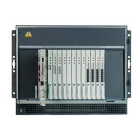
Signal conditioning........................................................................................................................... 519
Sanity timer...................................................................................................................................... 519
Microprocessor................................................................................................................................. 519
External timing interface................................................................................................................... 520
Hardware integrity and regulatory environment............................................................................... 520
Chapter 29: NTAK79 2.0 Mb PRI card................................................................................ 521
Contents.................................................................................................................................................... 521
Introduction............................................................................................................................................... 521
Physical description.................................................................................................................................. 522
NTAK79 switches............................................................................................................................. 523
Power requirements......................................................................................................................... 525
Environment..................................................................................................................................... 525
Functional description............................................................................................................................... 526
Architecture............................................................................................................................................... 526
DS-30X interface.............................................................................................................................. 527
Signaling interface............................................................................................................................ 528
Carrier interface................................................................................................................................ 528
Carrier grounding............................................................................................................................. 528
CEPT transceiver............................................................................................................................. 529
Slip control........................................................................................................................................ 530
D-channel support interface............................................................................................................. 530
Card-LAN interface........................................................................................................................... 531
Clock controller interface.................................................................................................................. 531
Chapter 30: NTDW79AAE5 Universal Digital Trunk card................................................ 535
Contents.................................................................................................................................................... 535
Introduction............................................................................................................................................... 535
Physical description.................................................................................................................................. 539
Power requirements......................................................................................................................... 540
Connectors....................................................................................................................................... 540
LED indicators.................................................................................................................................. 540
Functional description............................................................................................................................... 541
UDT card alarms.............................................................................................................................. 541
Clock reference................................................................................................................................ 542
Feature interactions.......................................................................................................................... 542
Chapter 31: NTAK93 D-channel Handler Interface daughterboard................................ 543
Contents.................................................................................................................................................... 543
Introduction............................................................................................................................................... 543
Physical description.................................................................................................................................. 544
Faceplate LEDs................................................................................................................................ 544
Power consumption.......................................................................................................................... 544
Functional description............................................................................................................................... 544
Microprocessors............................................................................................................................... 545
DMA controller.................................................................................................................................. 545
Random Access Memory (RAM)...................................................................................................... 545
Read Only Memory (ROM)............................................................................................................... 545
LAPD data link/asynchronous controller.......................................................................................... 545
Counter/timer controller.................................................................................................................... 545
14 Circuit Card Reference July 2011
Software interface circuit.................................................................................................................. 546
DPNSS/DCHI Port............................................................................................................................ 546
D-Port - SDTI/PRI interface.............................................................................................................. 546
Chapter 32: NTBK22 MISP card......................................................................................... 547
Contents.................................................................................................................................................... 547
Introduction............................................................................................................................................... 547
Physical description.................................................................................................................................. 547
Functional description............................................................................................................................... 548
Micro Processing Unit (MPU)........................................................................................................... 548
High-Level Data Link Controller (HDLC).......................................................................................... 548
CPU to MISP bus interface.............................................................................................................. 549
MISP network bus interface............................................................................................................. 549
Power consumption.......................................................................................................................... 549
Chapter 33: NTBK50 2.0 Mb PRI card................................................................................ 551
Contents.................................................................................................................................................... 551
Introduction............................................................................................................................................... 551
Physical description.................................................................................................................................. 552
Power requirements......................................................................................................................... 553
Environment..................................................................................................................................... 553
Functional description............................................................................................................................... 554
Architecture............................................................................................................................................... 554
DS-30X interface.............................................................................................................................. 555
Signaling interface............................................................................................................................ 556
Carrier interface................................................................................................................................ 556
Carrier grounding............................................................................................................................. 556
CEPT transceiver............................................................................................................................. 557
Slip control........................................................................................................................................ 558
D-channel support interface............................................................................................................. 558
Card-LAN interface........................................................................................................................... 558
Chapter 34: NTBK51 Downloadable D-channel Handler daughterboard....................... 561
Contents.................................................................................................................................................... 561
Introduction............................................................................................................................................... 561
Physical description.................................................................................................................................. 562
Functional description............................................................................................................................... 562
Microprocessors............................................................................................................................... 563
Main memory.................................................................................................................................... 563
Shared memory................................................................................................................................ 563
EPROM memory.............................................................................................................................. 563
Flash EPROM memory.................................................................................................................... 563
EEPROM memory............................................................................................................................ 564
Serial communication controller....................................................................................................... 564
Sanity timer...................................................................................................................................... 564
Bus timer.......................................................................................................................................... 564
Download operation.................................................................................................................................. 564
System initialization.......................................................................................................................... 565
Card enabling or application enabling.............................................................................................. 565
Card reset......................................................................................................................................... 565
Circuit Card Reference July 2011 15

Background audit............................................................................................................................. 565
Chapter 35: NTCK16 Generic Central Office Trunk cards............................................... 567
Contents.................................................................................................................................................... 567
Introduction............................................................................................................................................... 567
Physical description.................................................................................................................................. 568
Switch settings................................................................................................................................. 568
Self-test............................................................................................................................................ 569
Functional description............................................................................................................................... 569
Common features............................................................................................................................. 569
Operation.................................................................................................................................................. 570
Loop start operation......................................................................................................................... 570
Electrical specifications............................................................................................................................. 571
Power requirements......................................................................................................................... 571
Environmental specifications............................................................................................................ 572
Pad switching................................................................................................................................... 572
Connector pin assignments....................................................................................................................... 572
Cross connections............................................................................................................................ 572
Configuration............................................................................................................................................. 573
NTCK16AX Central Office trunk card............................................................................................... 576
NTCK16BX Central Office trunk card............................................................................................... 578
BTID values by country.................................................................................................................... 580
Applications............................................................................................................................................... 580
Periodic Pulse Metering................................................................................................................... 580
Busy tone detect............................................................................................................................... 581
Loss switching.................................................................................................................................. 581
Trunk to Trunk connection................................................................................................................ 582
Call disconnect................................................................................................................................. 583
Chapter 36: NTDW12AAE5 Universal Clock Controller daughter board....................... 585
Contents.................................................................................................................................................... 585
Introduction............................................................................................................................................... 585
Clocking modes................................................................................................................................ 586
Tracking mode.................................................................................................................................. 587
Free-run (non-tracking).................................................................................................................... 587
Physical description.................................................................................................................................. 588
Faceplate LEDs................................................................................................................................ 588
Functional description............................................................................................................................... 588
Phase difference detector circuit...................................................................................................... 589
Digital phase lock loops.................................................................................................................... 589
Digital to analog converter................................................................................................................ 591
Signal conditioning........................................................................................................................... 591
Sanity timer...................................................................................................................................... 591
Microprocessor................................................................................................................................. 591
Chapter 37: NTDW60 Media Gateway Controller Card.................................................... 593
Contents.................................................................................................................................................... 593
Introduction............................................................................................................................................... 593
Processor.................................................................................................................................................. 596
Ethernet ports............................................................................................................................................ 596
16 Circuit Card Reference July 2011

External connections........................................................................................................................ 596
Internal connections......................................................................................................................... 596
Expansion daughterboards....................................................................................................................... 596
Backplane interface................................................................................................................................... 597
Serial data interface ports......................................................................................................................... 597
TTY default settings......................................................................................................................... 597
MGC serial port configuration change.............................................................................................. 597
Faceplate LED display.............................................................................................................................. 598
Faceplate LED display..................................................................................................................... 598
Chapter 38: NTDW20 Media Gateway Extended Peripheral Equipment Controller card 599
Contents.................................................................................................................................................... 599
Introduction............................................................................................................................................... 599
Processors................................................................................................................................................ 602
Chagall-2 Core................................................................................................................................. 602
DSP processors............................................................................................................................... 602
Ethernet interfaces.................................................................................................................................... 603
Backplane interface................................................................................................................................... 603
DS-30X voice/signalling................................................................................................................... 603
Card LAN.......................................................................................................................................... 603
TTY ports.......................................................................................................................................... 603
LED indicators........................................................................................................................................... 604
Network connections and dual homing..................................................................................................... 604
Chapter 39: NTDW56 and NTDW59 Common Processor Media Gateway card............. 607
Contents.................................................................................................................................................... 607
Introduction............................................................................................................................................... 607
Cabinet and chassis support..................................................................................................................... 609
Faceplate.................................................................................................................................................. 610
Status LED................................................................................................................................................ 610
LED display............................................................................................................................................... 611
Serial data interface ports......................................................................................................................... 612
Ethernet connections................................................................................................................................ 612
Media storage........................................................................................................................................... 613
Security Device (Dongle).......................................................................................................................... 615
Chapter 40: NTDW53 and NTDW54 Common Processor Dual Core card...................... 617
Contents.................................................................................................................................................... 617
Introduction............................................................................................................................................... 617
Cabinet and chassis support..................................................................................................................... 618
Faceplate.................................................................................................................................................. 619
Status LED................................................................................................................................................ 619
Ethernet connections........................................................................................................................ 620
Serial data interface ports......................................................................................................................... 620
Media storage........................................................................................................................................... 621
Security Device (Dongle).......................................................................................................................... 622
Chapter 41: NTDW61 and NTDW66 Common Processor Pentium Mobile Card........... 623
Contents.................................................................................................................................................... 623
Introduction............................................................................................................................................... 623
Cabinet/chassis support............................................................................................................................ 626
Circuit Card Reference July 2011 17

Media storage........................................................................................................................................... 626
Fixed media drive............................................................................................................................. 626
Removable media drive.................................................................................................................... 626
Hard disk drive................................................................................................................................. 627
Memory..................................................................................................................................................... 630
Memory upgrade.............................................................................................................................. 630
Ethernet interfaces.................................................................................................................................... 635
ELAN................................................................................................................................................ 635
HSP.................................................................................................................................................. 636
TLAN................................................................................................................................................ 636
Serial data interface ports......................................................................................................................... 636
TTY parameters............................................................................................................................... 636
USB 2.0 port.............................................................................................................................................. 637
Security device.......................................................................................................................................... 637
Faceplate.................................................................................................................................................. 637
Faceplate buttons............................................................................................................................. 639
DIP switch........................................................................................................................................ 639
LED indicators........................................................................................................................................... 639
Status LED....................................................................................................................................... 639
Active CPU LED............................................................................................................................... 640
Ethernet LEDs.................................................................................................................................. 640
Removable and fixed media drive LEDs.......................................................................................... 641
Chapter 42: NTDW62, NTDW64, and NTDW78 Media Gateway Controller
Daughterboards.................................................................................................................. 643
Contents.................................................................................................................................................... 643
Introduction............................................................................................................................................... 643
Media Gateway Controller card................................................................................................................. 643
Daughterboard configurations................................................................................................................... 644
Chapter 43: NTDW65 Voice Gateway Media Card............................................................ 647
Contents.................................................................................................................................................... 647
Introduction............................................................................................................................................... 647
Ethernet ports............................................................................................................................................ 648
External connections................................................................................................................................. 648
Internal connections......................................................................................................................... 648
Backplane interfaces................................................................................................................................. 649
Serial data interface ports......................................................................................................................... 649
TTY settings..................................................................................................................................... 649
Faceplate LED display.............................................................................................................................. 649
Chapter 44: NTRB21 DTI/PRI/DCH TMDI card.................................................................. 651
Contents.................................................................................................................................................... 651
Introduction............................................................................................................................................... 651
Physical description.................................................................................................................................. 652
Power requirements......................................................................................................................... 655
Foreign and surge voltage protection............................................................................................... 655
Functional description............................................................................................................................... 655
Software description.................................................................................................................................. 656
Hardware description................................................................................................................................ 656
18 Circuit Card Reference July 2011
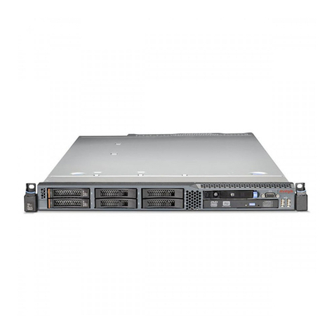
NTRB21 TMDI card.......................................................................................................................... 656
Architecture............................................................................................................................................... 656
Signaling interface............................................................................................................................ 656
Interconnection................................................................................................................................. 656
Microprocessor................................................................................................................................. 657
Digital pad........................................................................................................................................ 657
D-channel interface.......................................................................................................................... 658
DS-1 Carrier interface...................................................................................................................... 659
NTAK20 Clock Controller (CC) daughterboard................................................................................. 660
Chapter 45: NTVQ01xx Media Card................................................................................... 663
Contents.................................................................................................................................................... 663
Physical description.................................................................................................................................. 663
Hardware architecture............................................................................................................................... 664
Faceplate connectors and indicators................................................................................................ 664
Functional description............................................................................................................................... 667
Chapter 46: NTC314AAE6 Media Gateway utility card.................................................... 669
Contents.................................................................................................................................................... 669
Physical description.................................................................................................................................. 669
Functional description............................................................................................................................... 669
MGU dip switch settings............................................................................................................................ 671
Rear components............................................................................................................................. 674
Chapter 47: QPC841 Quad Serial Data Interface card..................................................... 677
Contents.................................................................................................................................................... 677
Introduction............................................................................................................................................... 677
Physical description.................................................................................................................................. 678
Functional description............................................................................................................................... 679
Connector pin assignments....................................................................................................................... 680
Configuring the QSDI card........................................................................................................................ 682
Address switch settings.................................................................................................................... 683
Baud rate switch settings................................................................................................................. 683
DTE/DCE mode switch settings....................................................................................................... 684
Test switch setting............................................................................................................................ 685
Software service changes................................................................................................................ 685
Applications............................................................................................................................................... 686
Index..................................................................................................................................... 689
Circuit Card Reference July 2011 19
20 Circuit Card Reference July 2011
Other manuals for 1000 Series
8
Table of contents
Other Avaya Server manuals

Avaya
Avaya S8400 Instruction Manual

Avaya
Avaya 1000 Series Guide

Avaya
Avaya CS700 Instruction Manual

Avaya
Avaya 1000 Series Service manual

Avaya
Avaya Aura S8800 User manual

Avaya
Avaya S8730 User manual

Avaya
Avaya CallPilot 202i User manual

Avaya
Avaya 1000 Series Instruction Manual

Avaya
Avaya CS 1000 Guide

Avaya
Avaya ESS User manual

Avaya
Avaya G700 Guide

Avaya
Avaya S8700 Series Supplement

Avaya
Avaya 1000E Supplement

Avaya
Avaya 1000 Series Guide

Avaya
Avaya Aura S8800 User manual

Avaya
Avaya S8700 Series User manual

Avaya
Avaya S8500B User manual

Avaya
Avaya S8300 Series User manual

Avaya
Avaya callpilot 1002rp Setup guide

Avaya
Avaya S8500 Series Mounting instructions