AVE VNI250/2PMF User manual

1
Leggere questo manuale attentamente prima di utilizzare il prodotto
e conservarlo in un posto sicuro così da poterlo consultare all’occorrenza.
Il prodotto è costruito a regola d’arte e nel rispetto delle normative vigenti in
materia di apparecchiature elettriche e deve essere installato da personale tecnicamente qualificato.
La ditta costruttrice non si assume responsabilità per danni a persone o cose derivanti dalla mancata osservanza delle norme contenute
nel presente libretto.
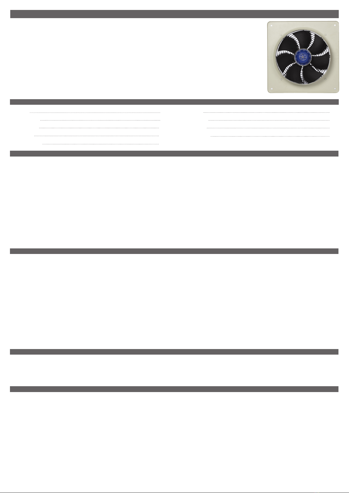
Manuale istruzioni
Gamma VNI - Ventilatori elicoidali
International Trademark registration n° 327040 - 942905 - 330600
1 INDICE
2 AVVERTENZE E PRECAUZIONI
2.1 E’ importante attenersi completamente a quanto riportato in queste Istruzioni di Montaggio e Manutenzione.
2.2 Tutti i dati del prodotto sono riportati sull’etichetta dati. In caso di dubbi, contattare il fornitore o un suo rappresentante.
2.3 Il collegamento elettrico deve essere eseguito da un personale professionale competente e qualificato in conformità ai requisiti vigenti pervisti dalla legge.
2.4 Queste istruzioni si riferiscono unicamente al ventilatore e non alla fornitura o installazione di dispositivi di sicurezza che possono essere necessari, come ad es. griglie o
protezioni adeguate per le parti rotanti e un appropriato isolamento elettrico.
2.5 Tutte le dichiarazioni rilasciate da produttore circa il montaggio e la sicurezza del prodotto sono subordinate al fatto che l’installazione stessa sia eseguita in conformità
alle norme e direttive vigenti nel proprio paese.
2.6 L’aspiratore è progettato per essere utilizzato ad una temperatura ambiente di -20°C fino ad un massimo di +70°C (fare riferimento alla tabella 2.a) e in presenza di un
tasso di Umidità Relativa fino a 95%. L’aspiratore non è adatto per atmosfere corrosive o esplosive.
2.7 L’installatore deve prevedere l’accesso facilitato al prodotto per facilitare le future operazioni di manutenzione.
2.8 L’Installatore deve assicurarsi che l’aspiratore sia supportato adeguatamente.
2.9 Questo apparecchio non è da intendersi adatto all’uso da parte di persone (incluso bambini) con ridotte capacità fisiche, sensoriali o mentali, o prive di esperienza e
conoscenza, a meno che non siano state supervisionate o istruite riguardo all’uso dell’apparecchio da una persona responsabile della loro sicurezza. I bambini dovrebbero
essere supervisionati per assicurarsi che non giochino con l’apparecchio.
ATTENZIONE - Assicurarsi che l’interruttore generale dell’impianto sia spento prima di qualsiasi operazione di manutenzione e installazione o collegamento elettrico!
ATTENZIONE - L’installazione e la manutenzione dell’unità e del sistema di ventilazione completo deve essere eseguito da un installatore autorizzato e in
conformità alle leggi e ai regolamenti vigenti.
ATTENZIONE - Il prodotto necessita della messa a terra secondo le norme locali vigenti.
3.1 Dopo averlo ricevuto verificare l’integrità del prodotto. Assicurarsi che la ventola sia libera di girare.
3.2 In caso di dubbi riguardanti il prodotto, contattare il produttore o il rappresentante prima di installarlo.
3.3 Assicurarsi che l’apparecchio sia fissato in sicurezza nella posizione desiderata secondo le necessità di applicazione. Può essere montato in qualsiasi posizione.
3.4 Verificare i dati di targa sul motore per assicurarsi che la rete (tensione, frequenza e fase) siano idonei.
Un errato collegamento alla rete è causa di un danno permanente del motore.
3.5 Fare riferimento allo schema elettrico corretto. Assicurarsi che venga eseguita la messa a terra.
3.6 Nell’installazione dell’impianto elettrico è necessario prevedere dispositivi di disconnessione elettrica, in conformità alle norme di collegamento ed elettriche vigenti.
3.7 Fare attenzione a posizionare la bocca di scarico in modo da evitare il ritorno di gas nella stanza derivante da condotti del gas aperti o da altri apparecchi funzionanti a combustibile.
3 INSTALLAZIONE
1 Indice p.1
2 Avvertenze e Precauzioni p.1
3 Installazione p.1
4 Messa in servizio p.1
5 Manutenzione p.1
6 Dati Prodotto p.3
6.1 Dati Elettrici p.3
6.2 Dimensioni p.3
7 Collegamenti Elettrici p.4
4.1 Prima di alimentare l’apparecchio, verificare che il cablaggio sia conforme allo schema di collegamento.
4.2 Al primo avvio verificare che il senso di rotazione della ventola e la direzione dell’aria siano corretti.
4.3 Verifica che l’amperaggio del motore non ecceda quanto indicato in targa.
ATTENZIONE - Assicurarsi che l’interruttore generale dell’impianto sia spento prima di qualsiasi operazione di manutenzione e installazione o collegamento elettrico!
ATTENZIONE - L’installazione e la manutenzione dell’unità e del sistema di ventilazione completo deve essere eseguito da un installatore autorizzato e in
conformità alle leggi e ai regolamenti vigenti.
5.1 Si raccomanda di ispezionare il prodotto almeno una volta ogni 12 mesi per assicurarsi che il motore, la ventola e i supporti siano puliti. Eventuali accumuli di polvere e
depositi sulle pale o sui supporti devono essere rimossi utilizzando un detersivo non abrasivo.
5.2 Verificare la tenuta di tutti i fissaggi. In aggiunta verificare la corretta rotazione delle parti rotanti.
5.3 I cuscinetti sono autolubrificati e non richiedono alcuna ispezione.
ATTENZIONE – Il prodotto è provvisto di protezione termica a riarmo automatico che spegne l’apparecchio in caso di anomalia. Dopo che il motore si è
raffreddato, il prodotto riparte inaspettatamente.
4 MESSA IN SERVIZIO
5 MANUTENZIONE

2
Installation manual
VNI Range - Plate axial fans
Read this manual carefully before using the product and keep it in a safe place for reference as necessary.
This product was constructed up to standard and in compliance with regulations relating to electrical equipment and must be installed
by technically qualified personnel.
The manufacturer assumes no responsibility for damage to persons or property resulting from failure to observe the instructions
contained in this manual.
2.1 It is important these Installation and Maintenance Instructions are fully adhered to.
2.2 Full details of the unit supplied are shown on the product nameplate. If in doubt about any detail contact the manufacturer or its agents for clarification.
2.3 All electrical installation must be carried out by suitably qualified and competent personnel in accordance with all current statutory requirements.
2.4 These instructions cover only the ventilation unit and do not include the supply or installation of any safety equipment that may be required e.g. adequate guarding or
protection from rotating parts and proper electrical isolation.
2.5 Any declarations made by the manufacturer about product installation and safety, are dependant on the fan equipment being used within installations which themselves
meet the requirements of the relevant Standards and Directives of your region.
2.6 The fan is designed for use in an ambient temperature of -20°C up to a maximum of +70°C (refer to the relevant table 2.a) and up to 95% relative humidity. The fan is
not suitable for corrosive or explosive atmospheres.
2.7 The installer should provide easy access to the fan to facilitate future maintenance.
2.8 The installer should ensure the fan is adequately supported.
2.9 The device is not intended for use by persons (including children) with reduced physical, sensory or mental capacities or those with a lack of experience and knowledge,
unless they have been given supervision or instruction concerning use of the device from a person responsible for their safety. Children should be supervised to ensure
that they do not play with the device.
WARNING - Make sure that the mains supply to the unit is disconnected before performing any installation, service, maintenance or electrical work!
WARNING - The installation and service of the unit and complete ventilation system must be performed by an authorized installer and in accordance with
local rules and regulations.
WARNING - The fan must be earthed in accordance with the local regulations.
3.1 Upon receipt, the fan equipment should be visually inspected to check for any damage. Ensure that the impeller is free to rotate.
3.2 If there are any queries concerning the fan equipment, the manufacturer or its agent should be contacted prior to the installation.
3.3 The fan must be securely mounted in the desired position to suit the application. The fan can be mounted at any angle.
3.4 Check the details on the motor rating plate to ensure that the correct power supply (voltage, frequency and phase) is available.
An incorrect power supply will lead to permanent damage to the fan motor.
3.5 Refer to the appropriate wiring diagram. Ensure that all earth connections are made.
3.6 Means for electrical disconnection must be incorporated in the wiring installation in accordance with the relevant wiring and electrical regulations.
3.7 Precaution must be taken to locate the exhaust discharge terminal so as to avoid the backflow of gases into the room from the open flue of gas or other fuel burning
appliances.
G
1 INDEX
1 Index p.2
2 Precautions p.2
3 Installation p.2
4 Start up p.2
5 Maintenance p.2
6 Product Data p.3
6.1 Eletrical Data p.3
6.2 Dimensions p.3
7 Wiring Diagrams p.4
2 PRECAUTIONS
3 INSTALLATION
4.1 Before power is supplied to the unit, check that the wiring is correct as per the fan connection diagram.
4.2 At initial start-up, check that impeller rotation and airflow direction is correct.
4.3 Check that the motor amperage drawn does not exceed the nameplate rating.
WARNING - Make sure that the mains supply to the unit is disconnected before performing any installation, service, maintenance or electrical work!
WARNING - The installation and service of the unit and complete ventilation system must be performed by an authorized installer and in accordance with
local rules and regulations.
5.1 Inspection of the fan at least once every 12 months is recommended to ensure that the motor, fan blades, and supporting guards, are clean. Any build up of dust and
deposits on the blades or guards should be removed using a non-abrasive cleaner.
5.2 All fastenings should be checked for tightness. In addition, all rotating items should be checked.
5.3 Bearings are of the ‘sealed for life’ type and will not need a detailed inspection.
WARNING – This fan is fitted with an auto-reset thermal contact which switches the fan off in the event of a fault condition. Once the motor cools down the
fan may start unexpectedly.
4 START UP
5 MAINTENANCE

3
6 DATI PRODOTTO/ PRODUCT DATA
Tabella/Table 2.a
6.1 Dati elettrici/Electrical Data
Codice
Code
Alimentazione
Supply
Dati elettrici motore
Motor elelctrical data
Max Temp. C°
Schema
elettrico nr.
Wiring
Diagram no.
FLC
Amps
Input
kW ∆ / Y
VNI250/2PMF 220-240V/1Ph/50Hz 0.59 0.137 2208 70 152-177
VNI250/4PMF 220-240V/1Ph/50Hz 0.24 0.049 1368 55 152-177
VNI315/4PMF 220-240V/1Ph/50Hz 0.67 0.137 1360 50 152-177
VNI350/4PMF 220-240V/1Ph/50Hz 0.77 0.177 1286 60 152-177
VNI400/4PMF 220-240V/1Ph/50Hz 1.08 0.244 1366 65 152-104
VNI450/4PMF 220-240V/1Ph/50Hz 2.45 0.554 1323 70 152-104
VNI500/4PMF 220-240V/1Ph/50Hz 3.35 0.762 1232 60 152-104
VNI560/4PMF 220-240V/1Ph/50Hz 5.10 1.204 1350 70 152-104
VNI560/6PMF 220-240V/1Ph/50Hz 2.30 0.463 951 70 152-104
VNI630/6PMF 220-240V/1Ph/50Hz 3.10 0.670 892 70 152-104
VNI500/46PTF 380-415V/3Ph/50Hz 1.46/0.96 0.83/0.55 1342/960 70 152-108
VNI560/46PTF 380-415V/3Ph/50Hz 2.40/1.25 1.20/0.65 1293/995 50 152-108
VNI630/46PTF 380-415V/3Ph/50Hz 3.43/2.50 2.60/1.60 1327/919 70 152-108
VNI710/46PTF 380-415V/3Ph/50Hz 4.88/2.89 2.65/1.74 1358/1091 60 152-108
FLC= corrente a pieno carico/full load current Input = corrente di spunto/starting current G/min= giri al minuto/rpm
'D'
'E'CTRS
4-HOLES Ø 'K'
Ø 'A'
Ø 'B'
Ø 'C'
'G'
'H'
'F' 'J'
FLYING LEAD COMPLETE
WITH TERMINAL BOX
6.2 Dimensioni/Dimensions (mm)
SCATOLA PORTA CONTATTI
TERMINAL BOX
4 FORI ØK
4 HOLES ØK
Codice
Code A B C D E F G H J K kg
VNI250/2PMF 254 257 276 370 320 43 48 6 24 7 4.5
VNI250/4PMF 254 257 276 370 320 43 48 6 19 7 4.5
VNI315/4PMF 317 329 365 430 380 18 71 11 13 9 7
VNI350/4PMF 358 370 400 485 435 51 74 12 9 9 8
VNI400/4PMF 400 412 450 540 490 56 95 15 - 10 9.5
VNI450/4PMF 450 462 500 575 535 20 95 15 51 10 16
VNI500/4PMF 504 517 584 655 615 63 104 16 37 11 21
VNI500/46PTF 504 517 584 655 615 63 104 16 38 11 21
VNI560/4PTF 560 577 620 725 670 60 100 15 66 10 27.5
VNI560/46PTF 560 577 620 725 670 60 100 15 64 10 24
VNI560/6PMF 560 577 620 725 670 60 100 15 44 10 22
VNI630/46PTF 635 648 728 805 750 80 130 20 53 11 38.5
VNI630/6PMF 635 648 728 805 750 60 130 20 25 11 25.5
VNI710/46PTF 711 715 799 850 810 71 150 20 38 14.5 40

4
7 COLLEGAMENTI ELETTRICI/WIRING DIAGRAMS
EAUXU1U2NLTK TK
N
LE
CONTROLLER TERMINAL BOX
BLUE
BROWN
230V 1PH 50Hz SUPPLY
FAN C/W ELECTRONIC SPEED CONTROL (149-EL_TK)
FAN
TB TB Z2 Z1 N/
U2
L/
U1
BLUE
BROWN
230V 1PH 50Hz SUPPLY
FAN
FAN C/W TRANSFORMER SPEED CONTROL (149-TC1_)
CONTROLLER TERMINAL BOX
EL N
NLENL AUX
THERMAL CUT-OUT
CONNECT TO
CONTROL CIRCUIT
L/
U1 N/
U2
Z1Z2TBTB
WHITE
WHITE
ORANGE
BLACK
BLUE
BROWN
GREEN/YELLOW
104B - COUNTER CLOCKWISE
FAN
230V 1PH 50Hz SUPPLY
NL E
TB TB Z2 Z1 N/
U2
L/
U1
THERMAL CUT-OUT
CONNECT TO
CONTROL CIRCUIT
ALL WIRING AND CONTROL EQUIPMENT MUST COMPLY TO THE
LATEST IEE REGULATIONS, IN PARTICULAR PART 552-01-02/03
11/07/2013
MK-152-104B Issue: Saved Date:
B
152-104
VENTILATORE
PROTEZIONE TERMICA
COLLEGATA AL
CIRCUITO DI
CONTROLLO
ALIMENTAZIONE
VENTILATORE CON REGOLATORE ELETTRONICO DI VELOCITA’ (149-EL_TK)
VENTILATORE
SCATOLA MORSETTIERA
REGOLATORE
ALIMENTAZIONE
VENTILATORE CON REGOLATORE DI VELOCITA’ AD AUTOTRASFORMATORE (149-TC1_)
VENTILATORE
PROTEZIONE TERMICA
COLLEGATA AL
CIRCUITO DI
CONTROLLO
SCATOLA MORSETTIERA
REGOLATORE
ALIMENTAZIONE
I COLLEGAMENTI E I DISPOSITIVI DI CONTROLLO DEVONO ESSERE CONFORMI AI REGOLAMENTI VIGENTI
BIANCO
BIANCO
ARANCIO
NERO
MARRONE
BLU
VERDE/GIALLO
MARRONE
BLU
230V 1PH 50Hz SUPPLY
MARRONE
BLU

5
BLUE
BROWN
BROWN
BLACK
BLUE OR GREY
GREEN/YELLOW
FAN
FAN C/W TRANSFORMER SPEED CONTROL (149-TC1_)
EL N U2 U1 AUX
N
LE
220-240V 1PH 50Hz
SUPPLY
CONTROLLER TERMINAL BOX
TO MOTOR
EL31
BLUE
BROWN
BROWN
BLACK
BLUE OR GREY
GREEN/YELLOW
FAN
FAN C/W ELECTRONIC SPEED CONTROL (149-EL31)
N/
U2
L/
U1
TO MOTOR
N/
U2
L/
U1
CONTROLLER TERMINAL BOX
220-240V 1PH 50Hz
SUPPLY
EL N
NLENL AUX
BROWN
BLACK
BLUE OR GREY
GREEN/YELLOW
PENL
230V 1PH 50Hz SUPPLY
TO MOTOR
FAN ONLY
5N LGND6 4
N L E
220-240V 1PH 50Hz
SUPPLY
CONTROLLER TERMINAL BOX
TO MOTOR
EL21
BLUE
BROWN
BROWN
BLACK
BLUE OR GREY
GREEN/YELLOW
FAN
FAN C/W ELECTRONIC SPEED CONTROL (EL21)
N/
U2
L/
U1
N/
U2
L/
U1
ALL WIRING AND CONTROL EQUIPMENT MUST COMPLY TO THE
LATEST IEE REGULATIONS, IN PARTICULAR PART 552-01-02/03
11/07/2013
MK-152-177 Issue: Saved Date:
B
152-177
ALIMENTAZIONE
SCATOLA MORSETTIERA REGOLATORE
VENTILATORE
VENTILATORE CON REGOLATORE DI VELOCITA’ ELETTRONICO (149-EL31) VENTILATORE CON REGOLATORE DI VELOCITA’ AD AUTOTRASFORMATORE (149-TC1_)
ALIMENTAZIONE
ALIMENTAZIONE SCATOLA MORSETTIERA
REGOLATORE EL21
VENTILATORE
SOLO VENTILATORE / FAN ONLY
AL MOTORE / TO MOTOR
VENTILATORE CON REGOLATORE DI VELOCITA’ ELETTRONICO (EL21)
NERO
MARRONE
BLU O GRIGIO
VERDE/GIALLO
NERO
MARRONE
BLU O GRIGIO
VERDE/GIALLO
MARRONE
BLU
NERO
MARRONE
BLU O GRIGIO
VERDE/GIALLO
VENTILATORE
NERO
MARRONE
BLU O GRIGIO
VERDE/GIALLO
SCATOLA MORSETTIERA REGOLATORE
ALIMENTAZIONE
MARRONE
BLU
MARRONE
BLU
I COLLEGAMENTI E I DISPOSITIVI DI CONTROLLO DEVONO ESSERE CONFORMI AI REGOLAMENTI VIGENTI
AL MOTORE /
AL MOTORE / AL MOTORE /

6
WHITE
WHITE
ORANGE
BROWN
RED
BLUE
GREY
BLACK
GREEN/YELLOW
BROWN
BLACK
GREY
BROWN
BLACK
GREY
GREY
RED
WHITE
WHITE
ORANGE
BLACK
BLUE
BROWN
GREEN/YELLOW
TO REVERSE ROTATION SWAP ANY TWO INCOMING SUPPLY CABLES
FAN ONLY
LOW SPEED STAR CONNECTION
L3L2
W1V2V1U2TB TB W2 U1
L1 PE
PE
L3L2
W1V2V1U2TB TB W2 U1
L1
TO MOTOR
TO MOTOR
HIGH SPEED DELTA CONNECTION
FAN C/W STAR/DELTA SWITCH
U1W2TBTB U2 V1 V2 W1
FAN TERMINAL BOX
STAR/DELTA
SWITCH
2 3 6 7 8
W1
V2
W2U2V1
U1
L3L2L1
1514129
L2
WV EL1 L2 L3 U
L1 L3 E
380-440V 3PH 50Hz
SUPPLY
CONTROLLER TERMINAL BOX
FAN C/W TRANSFORMER SPEED CONTROL (149-TC3_)
FAN TERMINAL BOX
GREY
BLACK
BROWN
BROWN
BLACK
GREY
GREEN/YELLOW
W1V2V1U2TB TB W2 U1
ALL WIRING AND CONTROL EQUIPMENT MUST COMPLY TO THE
LATEST IEE REGULATIONS, IN PARTICULAR PART 552-01-02/03
11/07/2013
MK-152-108 Issue: Saved Date:
D
152-108
COLLEGAMENTO A TRIANGOLO ALTA VELOCITA’
AL MOTORE
SOLO VENTILATORE AL MOTORE
COLLEGAMENTO A STELLA BASSA VELOCITÀ
PER INVERTIRE LA ROTAZIONE SCAMBIARE DUE FASI
SCATOLA MORSETTIERA
VENTILATORE
SCATOLA MORSETTIERA
REGOLATORE
VENTILATORE CON INTERRUTTORE STELLA/TRIANGOLO
SCATOLA MORSETTIERA
VENTILATORE
INTERRUTTORE STELLA/TRIANGOLO
BIANCO
BIANCO
ARANCIO
MARRONE
BLU
VERDE/GIALLO
ROSSO
GRIGIO
NERO
MARRONE
GRIGIO
NERO
BIANCO
BIANCO
ARANCIO
MARRONE
ROSSO
BLU
GRIGIO
NERO
VERDE/GIALLO
MARRONE
GRIGIO
NERO
GRIGIO
MARRONE
NERO
VERDE/GIALLO
MARRONE
GRIGIO
NERO
I COLLEGAMENTI E I DISPOSITIVI DI CONTROLLO DEVONO ESSERE CONFORMI AI REGOLAMENTI VIGENTI
FAN ONLY TO MOTOR
HIGH SPEED DELTA CONNECTION
TO MOTOR
LOW SPEED STAR CONNECTION
TO REVERSE ROTATION SWAP ANY TWO INCOMING
SUPPLY CABLES
FAN C/W TRANSFORMER SPEED CONTROL (149-TC3_)
FAN TERMINAL BOX
CONTROLLER TERMINAL BOX
FAN C/W STAR/DELTA SWITCH
FAN TERMINAL BOX
STAR/DELTA SWITCH
VENTILATORE CON REGOLATORE DI VELOCITA’ AD AUTOTRASFORMATORE (149-TC3_)

7
WHITE
WHITE
ORANGE
BROWN
RED
BLUE
GREY
BLACK
GREEN/YELLOW
BROWN
BLACK
GREY
BROWN
BLACK
GREY
GREY
RED
WHITE
WHITE
ORANGE
BLACK
BLUE
BROWN
GREEN/YELLOW
TO REVERSE ROTATION SWAP ANY TWO INCOMING SUPPLY CABLES
FAN ONLY
LOW SPEED STAR CONNECTION
L3L2
W1V2V1U2TB TB W2 U1
L1 PE
PE
L3L2
W1V2V1U2TB TB W2 U1
L1
TO MOTOR
TO MOTOR
HIGH SPEED DELTA CONNECTION
FAN C/W STAR/DELTA SWITCH
U1W2TBTB U2 V1 V2 W1
FAN TERMINAL BOX
STAR/DELTA
SWITCH
2 3 6 7 8
W1
V2
W2U2V1
U1
L3L2L1
1514129
L2
WV EL1 L2 L3 U
L1 L3 E
380-440V 3PH 50Hz
SUPPLY
CONTROLLER TERMINAL BOX
FAN C/W TRANSFORMER SPEED CONTROL (149-TC3_)
FAN TERMINAL BOX
GREY
BLACK
BROWN
BROWN
BLACK
GREY
GREEN/YELLOW
W1V2V1U2TB TB W2 U1
ALL WIRING AND CONTROL EQUIPMENT MUST COMPLY TO THE
LATEST IEE REGULATIONS, IN PARTICULAR PART 552-01-02/03
11/07/2013
MK-152-108 Issue: Saved Date:D

International Trademark
registration n °
327040 - 242905 - 330600
AVE S.p.A.
Via Mazzini, 75 - 25086 REZZATO (BS) - Italy
NOTE
Per la durata e le condizioni di garanzia dei singoli prodotti vedasi www.ave.it e il catalogo commerciale vigente.
I prodotti devono essere commercializzati in confezione originale, in caso contrario al rivenditore e/o installatore è fatto obbligo di applicare e di trasmettere all’utilizzatore le istruzioni
che accompagnano il prodotto e/o pubblicate su www.ave.it e sul catalogo commerciale vigente.
I prodotti AVE sono prodotti da installazione. Vanno installati da personale qualificato secondo le normative vigenti e gli usi, rispettando le istruzioni di conservazione, d’uso e di instal-
lazione di AVE S.p.A.
Si richiede inoltre il rispetto delle condizioni generali di vendita, note, avvertenze generali, avvertenze garanzie, reclami e avvertenze tecniche per l’installatore riportate su www.ave.it
e sul catalogo commerciale vigente.
C0620 - 00 - 010714
CFI00034 - 0416
This manual suits for next models
13
Table of contents
Languages:
Other AVE Fan manuals