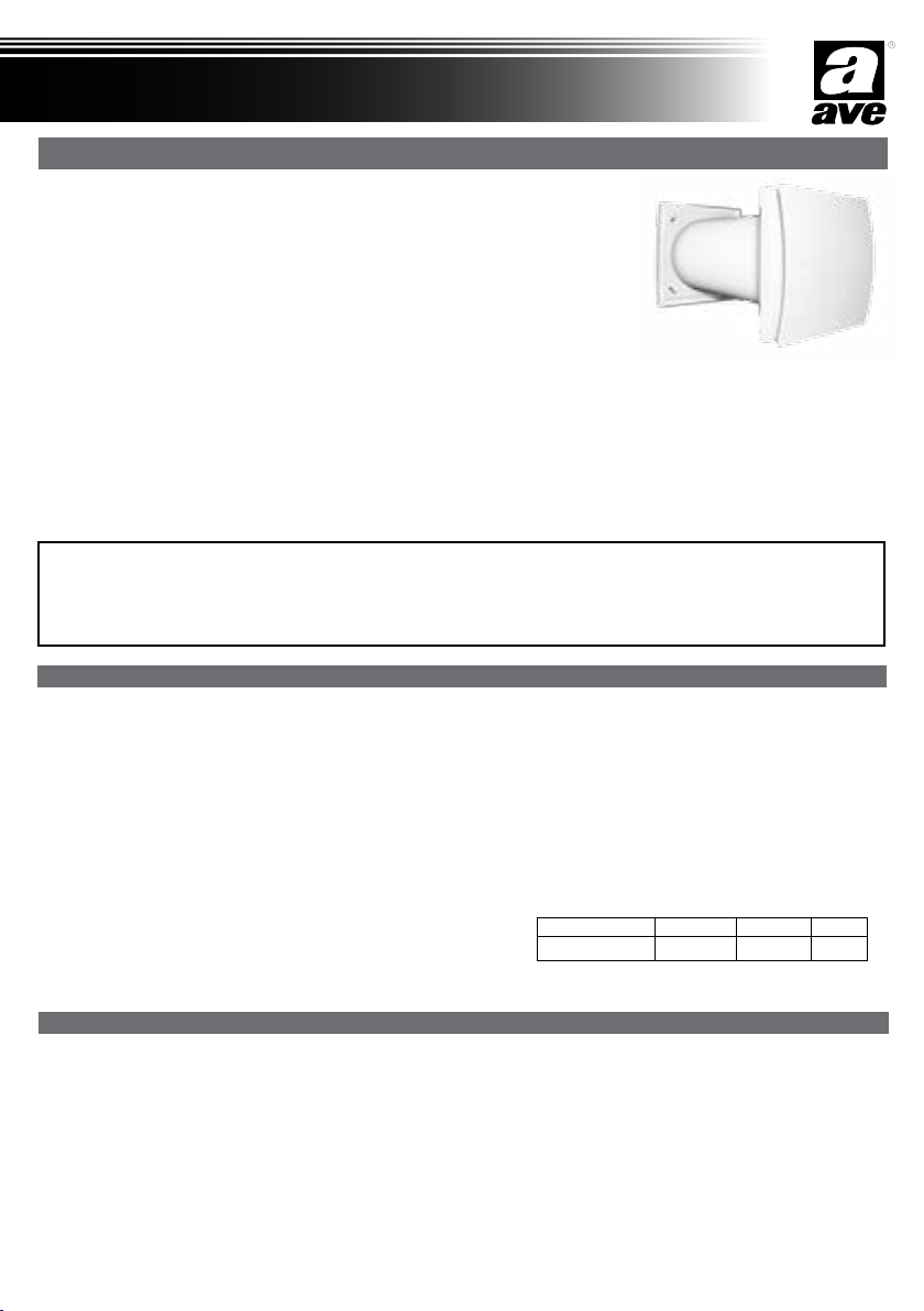
AVE VNRD150EC User manual

Introduzione
Solitair è un’unità di VMC puntuale a singolo flusso alternato con recupero di calore, anche nota come
unità «push&pull», progettata per garantire un’adeguata ventilazione in ambienti confinati, senza sprecare
energia e adatta per essere installata in ambienti nobili (soggiorno e camera da letto).
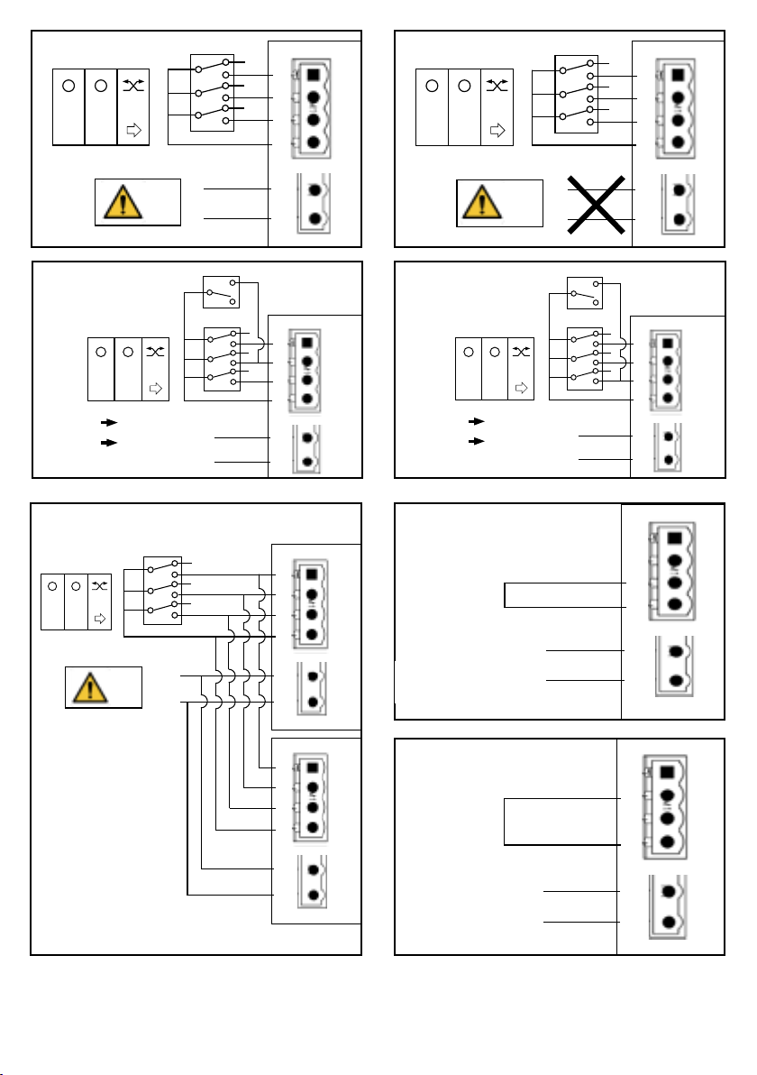
Per un migliore bilanciamento dei flussi si raccomanda di utilizzarla in coppia con un’altra unità, con
flussi sincronizzati tra di loro: quando un’unità estrae, l’altra immette.
Possono essere installate nello stesso ambiente o in stanze diverse (ad es. soggiorno e camera da letto)
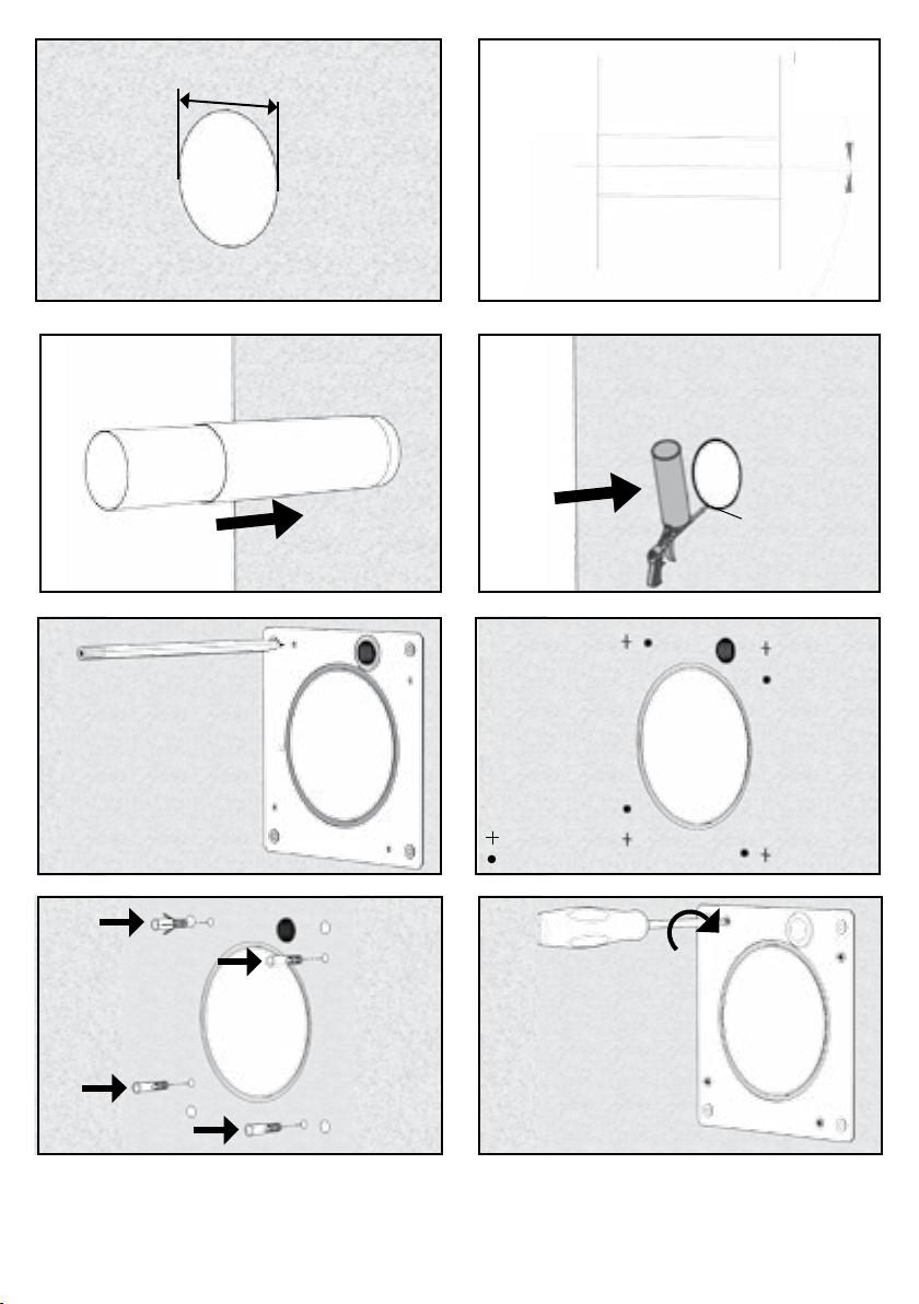
L’unità è adatta ad essere montata su pareti perimetrali.
Leggere questo manuale con attenzione prima di usare il prodotto e conservarlo in un posto sicuro così da poterlo consultare all’occorrenza.
Il prodotto è costruito a regola d’arte e nel rispetto delle normative vigenti in materia di apparecchiature elettriche e deve essere installato da
personale tecnicamente qualificato.
La ditta costruttrice non si assume responsabilità per danni a persone o cose derivanti dalla mancata osservanza delle norme contenute nel presente
libretto.
• Unità di ventilazione interna realizzata in ABS di alta qualità, resistente agli urti e ai raggi UV, colore RAL 9010
• Copri-frontale design smontabile per pulizia senza l’ausilio di utensili
• Piastra murale per semplicare le operazioni di manutenzione e facilitare l’accesso allo scambiatore di calore dall’interno della stanza
• Filtro anti-polvere lavabile removibile dall’interno da parte dell’utente senza l’ausilio di utensili
• Scambiatore di calore rigenerativo con pacco ceramico
• Griglia esterna in ABS di alta qualità, resistente agli urti e ai raggi UV, colore RAL 9010 con ree anti-insetto
• Ventola aerodinamica ad alta efficienza, con pale a “winglet”, cioè provviste di alette di estremità per ottimizzare la silenziosità e il rendimento
• Motore EC brushless monofase, reversibile, con protezione termica integrata
• Motore montato su cuscinetti a sfera che garantiscono al prodotto un ciclo di vita più lungo
• Realizzato in doppio isolamento: non necessita della messa a terra
• Velocità selezionabile
• Modalità free-cooling (bypass)
• Grado di protezione IPX4
• Alimentazione 220-240V~ 50Hz
Manuale istruzioni
Solitair
I
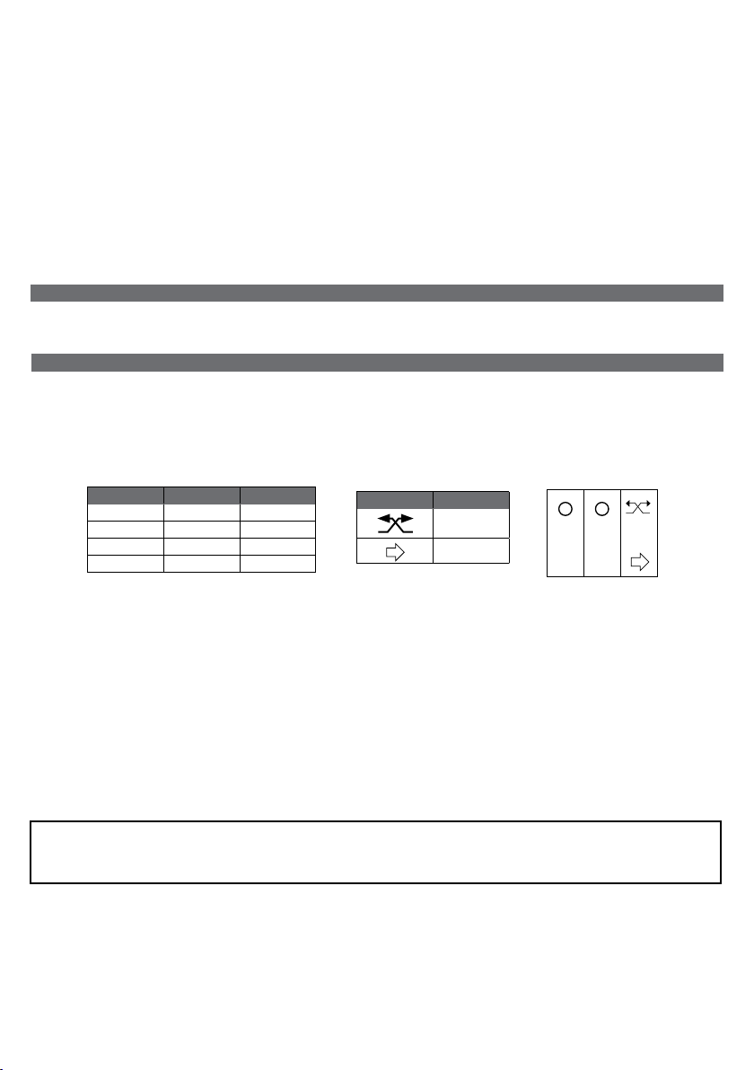
Modello Portata m3/h Consumo W Peso Kg
VNRD150EC 20/40/60 1,4/2,3/3,8 4,2
CARATTERISTICHE TECNICHE
PRECAUZIONI PER L’INSTALLAZIONE, L’USO E LA MANUTENZIONE
• L’apparecchio non deve essere utilizzato in applicazioni diverse da quelle indicate in questo manuale.
• Dopo aver rimosso il prodotto dall’imballo, assicurarsi della sua integrità; in caso di dubbio, rivolgersi a personale qualicato. Non lasciare parti
dell’imballo alla portata di bambini o persone diversamente abili.
• Non toccare l’apparecchio con mani/piedi umidi o bagnati.
• L’apparecchio non è destinato a essere usato da persone (bambini compresi) le cui capacità siche, sensoriali o mentali siano ridotte oppure
con mancanza di esperienza e di conoscenza, a meno che esse abbiano potuto beneciare, attraverso l’intermediazione di una persona
responsabile della loro sicurezza, di una sorveglianza o di istruzioni riguardanti l’uso dell’apparecchio.
I bambini devono essere supervisionati per assicurarsi che non giochino con l’apparecchio.
• Non impiegare il prodotto in presenza di sostanze o vapori inammabili, come alcool, insetticidi, benzina, etc.
• In caso si rilevi qualsiasi tipo di anomalia nel funzionamento, scollegare l’apparecchio dalla rete elettrica e rivolgersi al più presto a personale
qualicato. In caso di riparazione, richiedere esclusivamente ricambi originali.
L’unità dovrebbe funzionare continuamente ed essere spenta solo durante le operazioni di manutenzione.
Nei casi in cui sia sostanzialmente inutile la funzione di recupero calore (es.mezze stagioni con temperature interne ed esterne simili), o sia
opportuna la disattivazione dello scambio termico (es.free cooling estivo), si raccomanda di settare l’unità in sola estrazione/sola immissione
e di NON spegnerla.
International Trademark registration n° 327040 - 942905 - 330600

2
• L’impianto elettrico a cui e’ collegato il prodotto deve essere conforme alle normative vigenti.
• Prima di collegare il prodotto alla rete di alimentazione o alla presa elettrica accertarsi che:
- i dati di targa (tensione e frequenza) siano rispondenti a quelli della rete di distribuzione elettrica;
- la portata dell’impianto/presa sia adeguata alla potenza massima dell’apparecchio. In caso contrario rivolgersi a personale qualicato.
• L’ apparecchio non deve essere impiegato come attivatore di scaldabagni, stufe, ecc., nè deve scaricare in condotti adibiti all’evacuazione di aria
calda/fumi derivanti da alcun tipo di apparecchio a combustione. Deve espellere l’aria all’esterno tramite un proprio condotto specico.
• Temperatura di funzionamento: da -20°C no a +50°C.
• L’apparecchio è destinato ad estrarre solo aria pulita, ossia senza elementi grassi, fuliggine, agenti chimici e corrosivi, miscele inammabili o
esplosive.
• Non lasciare l’apparecchio esposto ad agenti atmosferici (pioggia, sole, neve, etc.).
• Non immergere I’apparecchio o altre sue parti in acqua o liquidi.
• Spegnere l’interruttore generale dell’impianto ogni qual volta si rilevi un’anomalia di funzionamento o si effettuino operazioni di pulizia.
• Per l’installazione occorre prevedere nella rete di alimentazione, conformemente alle regole di installazione, un interruttore onnipolare che
consenta la disconnessione completa nelle condizioni della categoria di sovratensione III (distanza dei contatti uguale o superiore a 3 mm).
• Se il cavo di alimentazione è danneggiato, esso deve essere sostituito dal costruttore o dal suo servizio assistenza tecnica o comunque da una
persona con qualica similare, in modo da prevenire ogni rischio.
• Non ostruire la griglia di aspirazione o di espulsione per garantire l’ottimale passaggio dell’aria.
• Assicurare un adeguato afusso/deusso dell’aria nel locale, nel rispetto del regolamento vigente, al ne di garantire il corretto funzionamento
dell’apparecchio.
• Qualora nell’ambiente in cui è installato il prodotto sia presente un apparecchio funzionante a combustibile (scaldacqua, stufa a metano etc.,
di tipo non a “camera stagna”), è indispensabilie assicurare un adeguato ingresso d’aria, per garantire una buona combustione e il corretto
funzionamento di tali apparecchi.
L’unità espelle l’aria per circa 70 secondi per poi invertire la direzione ed immettere l’aria per lo stesso periodo di tempo.
Quando l’aria riscaldata viene estratta verso l’esterno, riscalda lo scambiatore di calore ceramico; quando l’aria fredda viene immessa
all’interno, viene pre-riscaldata, recuperando l’energia termica che altrimenti verrebbe persa durante il processo di ventilazione.
L’unità funziona alla velocità selezionata agendo sull’interruttore “S1”, “S2” e “S3” del 441001K3RC, 442001K3RC,443001K3RC (accessorio
Fig.57). Le stesse modalità di funzionamento possono essere ottenute con il 441001K3RC, 442001K3RC,443001K3RC oppure con 3 interruttori
NA.
L’interruttore S3 attiva la funzione “Free cooling “ (Bypass), interrompendo il usso alternato in modo che l’unità operi in modalità “solo estrazione”
o “solo immissione”, per evitare lo scambio di calore quando non richiesto. Per denire la modalità “solo estrazione” o “solo immissione”,
posizionare opportunamente i jumper integrati (Fig.20A e Fig.20B). Il LED posto sul frontale indica che la modalità Free Cooling è attiva.
L’aumento della velocità può essere ottenuto automaticamente tramite sensori ambiente quali 441079, 442079,
443079, 441068RL, 442068RL, 443068RL o Sensore RG1/CO2, connettendolo in parallelo al devitatore S2.
Schema di collegamento singola unità: Fig. 18A
Schema di collegamento con sensori ambiente: Fig. 18B e Fig. 18C
Schema di collegamento di più unità: Fig. 18D
L’accessorio 441001K3RC, 442001K3RC,443001K3RC può comandare sino a 10 unità contemporaneamente.
“S1” “S2” Funzionamento
O O OFF
I O Velocità 1
O II Velocità 2
I II Velocità 3
S1 S2 S3
II
I
“S3” Funzionamento
Recupero calore
(usso alternato)
Free cooling
FUNZIONAMENTO
VERSIONI
STANDARD
Provvisto di griglia esterna in ABS di alta qualità, colore RAL 9010, resistente agli urti e ai raggi UV, con rete anti-insetto
ATTENZIONE:
Rispettare l’ordine di connessione elettrica di fase (L) e neutro (N). Una connessione errata potrebbe causare malfunzionamento o danni
permanenti all’unità

3
2014/35/UE Direttiva Bassa Tensione e 2014/30/UE Direttiva di Compatibilità Elettromagnetica, secondo lo stato dell’arte delle seguenti norme:
Sicurezza elettrica EN60335-1(2008); EN 60335-2-80(2005); EN 60335-2-80/A2(2009),
Compatibilità Elettromagnetica EN 55014-1(2006)+A1+A2; EN 55014-2(1997)+A1(2001)+A2(2008)+IS1(2007), EN 61000-3-2(2006)+A1(20
09)+A2(2009); EN 61000-3-3(2008).
CONFORMITA’ NORMATIVA
Due o più unità possono funzionare alla stessa velocità ssa in modo sincronizzato (una estrae e l’altra immette, e viceversa).
Schema di collegamento: Fig.18 E-F-G
La direzione del usso alla prima accensione dell’unità si ottiene settando il jumper dedicato (Fig.20A-20B)
RESET DELLA SINCRONIZZAZIONE
OPZIONE 1
Se due o più unità sono collegate sotto lo stesso interruttore generale, o sotto lo stesso interruttore dedicato, spegnere l’interruttore e poi
riaccenderlo (Fig.31)
OPZIONE 2
Se due o più unità non sono collegate sotto lo stesso interruttore generale, premere contemporaneamente il tasto nero di ogni unità come da Fig.40,
per almeno 3 secondi (Fig.32-33)
SINCRONIZZAZIONE IN CASO DI INSTALLAZIONE SENZA CONTROLLO
La manutenzione ordinaria può essere eseguita dall’utente come indicato a Pag. 14
La manutenzione straordinaria deve essere eseguita unicamente da personale tecnicamente qualicato e i conformità alle norme e regolamenti
locali in vigore, assicurandosi che l’interruttore generale dell’impianto sia spento (Pag.15).
La pulizia dello scambiatore può essere effettuata anche dall’esterno.
MANUTENZIONE
Il jumper integrato in posizione A (g.20A) denisce la funzione “estrazione”.
Il jumper integrato in posizione B (g.20B) denisce la funzione “immissione”.
Il posizionamento del jumper determina la direzione del usso dell'aria all'avvio della macchina (per la sincronizzazione) così come la direzione del
usso dell'aria in modalità free cooling.
POSIZIONAMENTO jUMPER
Se due o più unità sono collegate sotto lo stesso controllo, funzionano sempre in modo sincronizzato.
Schema di collegamento: Fig.18D
SINCRONIZZAZIONE IN CASO DI INSTALLAZIONE CON CONTROLLO

4
Introduction
Solitair is a single alternate flow decentralized (single point) residential heat recovery unit, also called
«push&pull» unit, designed to ensure adequate ventilation in enclosed environments without energy
losses and designed to be installed in ambients like living room and bedrooms.
It is recommended that two units are installed in pair: when one unit is pulling, the other is pushing.
Pair of units can be installed in the same room or in different rooms (i.e. livingroom and bedroom).
The unit is suitable for installation on an outside wall.
Read this manual carefully before using the product and keep it in a safe place for reference.
This product was constructed up to standard and in compliance with regulations relating to electrical equipment and must be installed by technically
qualified personnel.
The manufacturer assumes no responsibility for damage to persons or property resulting from failure to observe the regulations contained in this
booklet.
• Inner ventilation unit material: high quality, impact and UV-resistant ABS colour RAL 9010
• Design front cover removable for cleaning without the use of tools
• Easy maintenance installation plate, for easy access to the heat exchanger from inside the room
• Anti-dust lter, easily removable for washing by the user without tools
• Regenerative honeycombs ceramic heat exchanger
• External grille in high quality, impact and UV-resistant ABS colour RAL 9010 with anti-insect net
• High efciency aerodynamic fan with “winglet” blades to optimise quietness and efciency
• Single phase EC reversible Brushless motor with integral thermal protection
• Motor mounted on high quality ball bearings.
• The unit is double insulated: no earth connection is required
• Trickle speed selectable.
• Free-cooling (Bypass) mode.
• IPX4 degree of protection
• Power supply 220V to 240V~ 50Hz
• The device should not be used for applications other than those specied in this manual.
• After removing the product from its packaging, verify its condition. In case of doubt, contact a qualied technician. Do not leave packaging
within the reach of small children or people with disabilities.
• Do not touch the appliance with wet or damp hands/feet.
• The device is not intended for use by persons (including children) with reduced physical, sensory or mental capacities or those with a lack of
experience and knowledge, unless they have been given supervision or instruction concerning use of the device from a person responsible for
their safety.
Children should be supervised to ensure that they do not play with the device.
• Do not use the product in the presence of inammable vapours, such as alcohol, insecticides, gasoline, etc.
• If any abnormalities in operation are detected, disconnect the device from the mains supply and contact a qualied technician immediately. Use
original spare parts only for repairs.
• The electrical system to which the device is connected must comply with regulations.
• Before connecting the product to the power supply or the power outlet, ensure that:
- the data plate (voltage and frequency) correspond to those of the electrical mains
- the electrical power supply/socket is adequate for maximum device power. If not, contact a qualied technician.
Installation manual
Solitair
TECHNICAL SPECIFICATIONS
PRECAUTIONS FOR INSTALLATION, USE AND MAINTENANCE
G
The unit should operate continuously, and only stopped for maintenance or service.
When heat exchange is not useful (for example in mid-seasons when indoor and outdoor temperatures are similar), or when heat exchange
is not recommended (for example with the option “summer free cooling”), it is recommended to set the unit in “extract-only” or “intake-only”
mode and NOT to switch it off.
Model Airflow m3/h Power W Weight Kg
Solitair 150 20/40/60 1,4/2,3/3,8 4,2

5
The unit pulls air out for 70 seconds, then it pushes air in for the same time.
When heated air is pulled (extracted) from inside the room, it warms up the heat exchanger; when the cold air is pushed (supplied)
in the room, it gets preheated, recovering most of thermal energy which would be otherwise lost in the ventilation process.
The unit runs at the speed selected by activating the switches “S1”, “S2” and “S3” of the 441001K3RC, 442001K3RC,443001K3RC (accessory
Fig. 57). The same functionality can be achieved with 441001K3RC, 442001K3RC,443001K3RC or with 3 switches NO.
S3 switch activates the “Free cooling “ (Bypass) mode , which stops alternate ow and keeps the fan in “extract-
only” or “intake-only” mode, to avoid the heat exchange when necessary. To set the extract-only” mode or “intake-only”,
place the integral jumpers as per Fig.20A or Fig.20B).The front cover LED indicates when the Free cooling mode is on.
The speed increase can be automatically achieved through room sensors like 441079, 442079, 443079,
441068RL, 442068RL, 443068RL or RG1/CO2 sensor, connecting such switch in parallel to the S2 switch.
Wiring diagram of one unit: Fig. 18A
Wiring diagram with ambient sensors: Fig.19B and Fig.18C
Wiring diagram of two or more units: Fig.18D
The accessory 441001K3RC, 442001K3RC,443001K3RC can controll up until 10 units at the same time.
VERSIONS
“S1” “S2” Operation
O O OFF
I O Speed 1
O II Speed 2
I II Speed 3
S1 S2 S3
II
I
“S3” Operation
Heat recovery
(Alternate ow)
Free cooling
OPERATION
• The device should not be used as an activator for water heaters, stoves, etc., nor should it discharge into hot air/fume vent ducts deriving from
any type of combustion unit. It must expel air outside via its own special duct.
• Operating temperature: -20°C up to +50 °C.
• The device is designed to extract clean air only, i.e. without grease, soot, chemical or corrosive agents, or ammable or explosive mixtures.
• Do not leave the device exposed to atmospheric agents (rain, sun, snow, etc.).
• Do not immerse the device or its parts in water or other liquids.
• Turn off the main switch whenever a malfunction is detected or when cleaning.
• For installation an omnipolar switch should be incorporated in the xed wiring, in accordance with the wiring regulations, to provide a full
disconnection under overvoltage category III conditions (contact opening distance equal to or greater than 3mm).
• If the supply cord is damaged, it must be replaced by the manufacturer, its service agent or similarly qualied persons in order to avoid a
hazard.
• Do not obstruct the fan or exhaust grille to ensure optimum air passage.
• Ensure adequate air return/discharge into/from the room in compliance with existing regulations in order to ensure proper device operation.
• If the environment in which the product is installed also houses a fuel-operating device (water heater, methane stove etc., that is not a “sealed
chamber” type), it is essential to ensure adequate air intake, to ensure good combustion and proper equipment operation.
STANDARD
External grille in high quality, impact and UV-resistant ABS colour RAL 9010.
WARNING:
Ensure that the electric wiring to L and N is done correctly; an incorrect connection will lead to malfunction or permanent damage of the fan

6
STANDARD CONFORMITY
2014/35/EU Low Voltage Directive (LVD) and 2014/30/EU Electromagnetic Compatibility (EMC), in conformity with the following standards:
Electrical Safety EN60335-1(2008); EN 60335-2-80(2005); EN 60335-2-80/A2(2009)
Electromagnetic Compatibility EN 55014-1(2006)+A1+A2; EN 55014-2(1997)+A1(2001)+A2(2008)+IS1(2007), EN 61000-3-2(2006)+A1(200
9)+A2(2009); EN 61000-3-3(2008).
Maintenance can be carried out by the user as indicated at page 14
Service must be perfmormed only by technically qualied personnel in accordance with local rules and regulations. Make sure that the mains
supply to the unit is disconnected (page 15).
Cleaning of the heat exchanger can be performed from outside as well.
MAINTENANCE AND SERVICE
Integral jumper set in position A (Fig.20A) means “extract” mode.
Intergal jumper set in position B (Fig.20B) means “intake” mode.
The jumper position denes both the air-ow direction when the unit is activated for the rst time (for the synchronisation) and the air-ow direction
of the free-cooling mode.
jUMPER POSITION
Two or more units can operate at a xed speed in a synchronised way (one unit extracts, the other supplies, and viceversa). Wiring diagrams: Fig
18E-F-G
The initial starting air direction is achieved by setting the dedicated jumper (Fig. 20A-20B)
RESET OF THE SYNCHRONISATION
OPTION 1
If two or more units are connected under the same main switch or under a dedicated switch, to reset the synchronisation, the switch must be
switched rst OFF and then ON to reactivate (Fig.31)
OPTION 2
If two or more units are not connected under the same main switch, to reset the synchronisation, press at the same time the black pin of each unit
(g.40) for at least 3 seconds (Fig.32-33)
SYNCHRONISATION IN CASE OF INSTALLATION WITHOUT CONTROLLER
If two or more units are controlled by means of the same controller (149-SEN-CTRLS or similar), they always operate in a synchronised way. Wiring
diagram as per Fig. 18D
SYNCHRONISATION IN CASE OF INSTALLATION WITH CONTROLLER

7
270÷510
164
q
164
q
108
O
mm
A
270÷510
164
q
164
q
108
O
mm
270÷510
164
q
164
q
108
O
mm
C
E
FØ
Griglia esterna - External grille
Versione standard - Standard version
270÷510
164
q
164
q
108
O
mm
B
VNRD150EC
A218
B 51
C218
E 300÷560
F Ø 158
DIMENSIONI - DIMENSIONS (mm)
INSTALLAZIONE - INSTALLATION
1
CONTENUTO IMbALLO MODELLO SOLITAIR
VNRD150EC

8
3
4
3
5
min. 158mm INTERNO
INDOOR
ESTERNO
OUTDOOR
1° ÷ 2°
2
schiuma d’isolamento
insulation foam
67
8 9
=Ø 5x40mm
=Ø 8x10mm

9
10
12 13
11
115mm HR150
14 15
16 17

10
S3 S2 S1 GND N L
CTRL-S
S1 S2 S3
II
I
N
L
OK
L
L
L
1
1
1
2
2
2
18A
S3 S2 S1 GND N L
CTRL-S
S1 S2 S3
II
I
L
N
NO!
L
L
L
1
1
1
2
2
2
18A
S3 S2 S1 GND
N L
CTRL-S
S1 S2 S3
II
I
N
L
HY/CO2
0 2
1 3
L
L
L
1
1
1
2
2
2
18b
S3 S2 S1 GND N L
CTRL-S
S1 S2 S3
II
I
L
L
L
1
1
1
N
L
HY/CO2
0 1
2 3
2
2
2
18C
S3 S2 S1 GND N L
CTRL-S
S1 S2 S3
II
I
N
L
OK
L
L
L
1
1
1
2
2
2
S3 S2 S1 GND N L
18D
UNIT 1 UNIT 2
S3 S2 S1 GND
N L
18E
S3 S2 S1 GND N L
18F
VELOCITA’ FISSA 1
SPEED 1 (FIXED)
VELOCITA’ FISSA 2
SPEED 2 (FIXED)

11
AGGIUNTA FOGLIO ISTRUZIONI -
jUMPER POSITION A
20A
ESTRAZIONE
EXTRACT
23
CLICK
21
AGGIUNTA FOGLIO ISTRUZIONI -
jUMPER POSITION b
20b
IMMISSIONE
INTAKE
22
S3 S2 S1 GND N L
18G
VELOCITA’ FISSA 3
SPEED 3 (FIXED)
24

12
25
27
26
Ø 5x40mm
3-5mm
EXTERNAL GRILLE
29
28
30b
GRIGLIA ESTERNA
30A

13
RESET DELLA SINCRONIZZAZIONE DELLE UNITA’ (OPZIONE 1)
31
32
TO RESET OF THE SYNCHRONIZATION OF THE UNITS (OPTION 2)
33A
TO RESET OF THE SYNCHRONIZATION OF THE UNITS (OPTION 1)
RESET DELLA SINCRONIZZAZIONE DELLE UNITA’ (OPZIONE 2)
S3 S2 S1 GND
N L
33b

14

15
34 35
36 37
38
I
39
40 41
I
PULIZIA FILTRO (MANUTENZIONE ORDINARIA)
FILTER CLEANING (MAINTENANCE)
Può essere eseguita dall’utente
Can be carried out by the user

16
71
48 49
44 45
46
42 43
47
PULIZIA SCAMbIATORE (MANUTENZIONE STRAORDINARIA)
HEAT EXCHANGER CLEANING (SERVICE)
Deve essere eseguita unicamente da personale tecnicamente qualicato
Must be carried out only by technically qualied personnel

17
71
51
56
50
53
52
115mm HR150
54 55
Fig. 57
441001K3RC,
442001K3RC,443001K3RC
II I
COMANDO ESTERNO (su richiesta)
ALTAMENTE RACCOMANDATO
REMOTE CONTROLLER (on request)
HIGHLY RECOMMENDED

18
a) Marchio - Mark -AERAULIQA
b) Modello - Model -VNRD150EC
c) Classe SEC - SEC class -A
c1) SEC climi caldi - SEC warm climates kWh/m2.a -16,2
c2) SEC climi tempera - SEC average climates kWh/m2.a -38,2
c3) SEC climi freddi - SEC cold climates kWh/m2.a -76,4
Echea energeca; Energy label -Yes
d) Tipologia unità - Unit typology -Residenziale - bidirezionale
e) Tipo azionamento - Type of drive -azionamento a velocità mulple;
mul-speed drive
f) Sistema di recupero calore - Type of Heat Recovery System -a recupero; heat recovery
g) Ecienza termica- Thermal eciency of heat recovery %74%
h) Portata massima - Maximum ow rate m3/h 60
i) Potenza elerica (alla portata massima)
Electric power input at maximum ow rate W3,8
j) Livello potenza sonora (LWA) - Sound power level (LWA)dBA 38
k) Portata di riferimento - Reference ow rate m3/h 41
l) Dierenza di pressione di riferimento - Reference pressure dierence Pa 10
m) Potenza assorbita specica (SPI); Specic power input (SPI) W/m3/h 0,054
n1) Faore di controllo - Control factor -1
n2) Tipologia di controllo - Control typology -Controllo manuale (senza DCV);
Manual control (no DCV)
o1) Tralamento interno massimo - Maximum internal leakage rate %N/A
o2) Tralamento esterno massimo - Maximum external leakage rate %1%
Direttiva ErP - Regolamenti 1253/2014 - 1254/2014
ErP Directive - Regulations 1253/2014 - 1254/2014

p1) Tasso di miscela interno - Internal mixing rate %N/A
p2) Tasso di miscela esterno - External mixing rate %N/A
q) Segnale avvermento ltro - Visual lter warning -N/A
r) Istruzioni installazione griglie - Instrucons to install regulated grilles -N/A
s) Indirizzo Internet istruzioni di preassemblaggio/disassemblaggio
Internet address for preassembly/disassembly instrucons -www.ave.it
t) Sensibilità del usso alle variazioni di pressione
Airow sensivity to pressure variaons %N/A
u) Tenuta all’aria interna/esterna - Indoor/outdoor air ghtness m3/h 60
v1) Consumo annuo di energia (AEC) climi caldi
AEC - Annual electricity consumpon - warm climates kWh 0,7
v2) Consumo annuo di energia (AEC) climi tempera
AEC - Annual electricity consumpon - average climates kWh 0,7
v3) Consumo annuo di energia (AEC) climi freddi
AEC - Annual electricity consumpon - cold climates kWh 0,7
w1) Risparmio di riscaldamento annuo (AHS) climi caldi
AHS - Annual heang saved - warm climates kWh 18,1
w2) Risparmio di riscaldamento annuo (AHS) climi tempera
AHS - Annual heang saved - average climates kWh 40
w3) Risparmio di riscaldamento annuo (AHS) climi freddi
AHS - Annual heang saved - cold climates kWh 78,2
NOTE
This manual suits for next models
1
Table of contents
Other AVE Fan manuals
Popular Fan manuals by other brands

INNOLIVING
INNOLIVING INN-505 user manual

ECRON
ECRON YTSF40-22 user manual

Home Decorators Collection
Home Decorators Collection TRUDEAU YG545A-EB Use and care guide

IRIS
IRIS WOOZOO PCF-SDC15T Series instruction manual

Aereco
Aereco V2A installation instructions

Lasco
Lasco 4890 Important instructions & operating manual