AVIRE Memcom+ User manual

1
Memcom+Emergency
Telephone
Installation Guide
Ref No. 453 900 (ML) GB Version 3
System Components
Cable Housing
Terminal Block
Memcom+ Unit
External Microphone

22
TOC – Top Of Car Version 453 211
COP - Car Operating Panel Version 453 200
453/201
1. Using the screws provided, install the Memcom+unit
to the top of the lift car. The rubber feet must not be
removed as this can create feedback.
2. Connect the telephone line, the lift alarm push button
and any required accessories as per the wiring diagrams
shown on Page 3 of this guide.
3. The Memcom+TOC 4m external microphone will need
installing into the COP or to a high position in the car, such
as in a false ceiling or air vent. It may be necessary to test
the optimum microphone location.
4. Always connect the earth rst before applying
90-230VAC
Earthing not required for 24VDC operation. Connect 0VDC
connection rst if 24VDC supply is not turned o.
1. Install the Memcom+Unit to the back of the lift car
operating panel in advance.
2. Connect the telephone line, the lift alarm push button
and any accessories required.
3. Earthing not required for 24VDC operation. Connect
0VDC connection rst if 24VDC supply is not turned o.
Installation

33
Installation
Wiring Diagram
Wiring into a proprietary system?
Whether you are looking to wire into the alarm push button or pictograms in an installed lift, or trying to integrate the Memcom+unit into a Lift Monitoring system, we can help. We
have wiring diagrams available to explain how to wire in the unit, pre-connected wiring looms and a trained technical service team to ensure the installation is clear and simple.
Phone cable colours vary
from site to site, please check
local wiring diagrams
MPS stations (492 021) connected in parallel
0V 0V 0V
Alarm Light Speak Light Alarm Button
End of Alarm
(Optional) N/O
* not required for
453 200 24V DC only COP
453 211 24V DC only COP
0V
PSTN (GSM Tip)
PSTN (GSM Ring)
MPS
MPS
Siren (Relay)
Siren (Relay)
Alarm Pictogram (+)
Speak Pictogram (+)
Alarm Button
End of Alarm
Common / Technical Input 1
Lift Status (5-24V DC) / Technical Input 1
24V DC
0V DC
Service Counter (+) / Technical Input 2
Service Counter (-) / Technical Input 2
230V AC Live
Door Filtering (5-24V DC)
230V AC Neutral
Earth
Door Filtering
Lift Status
90-230V AC* Input
Service Counter
12-230V AC/DC
24V DC Input
5-24V DC Input
Common Input
12 & 13
Default N/O
+
-
+
Siren External PSU
required

44
External
Microphone
Connector
External Speaker
Connector
Inductive
Loop
Connector
RS232 Connector
Installation
12VDC Output
(permanent)

55
Quick Start Guide
Language Selection
The rst time the Memcom+unit is
powered up, it will automatically
load the language selection. Using
the up and down arrows scroll to the
required language and press #.
Once you have selected the correct
language the Memcom+will load the
Quick Start menu, which is mapped
out to the right.
#
*
Simply follow the quick start guide
on this page to set up the essential
programming of the unit.
If you require details of the full menu
structure available then please refer
to pages 7-14 of this guide.
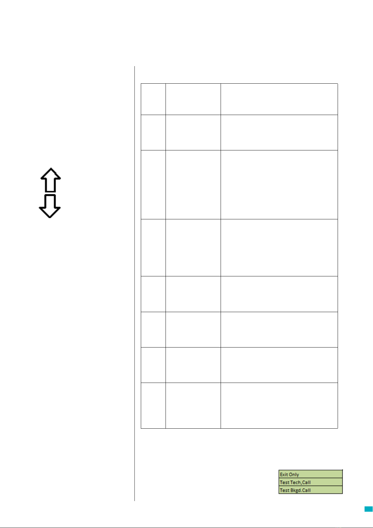
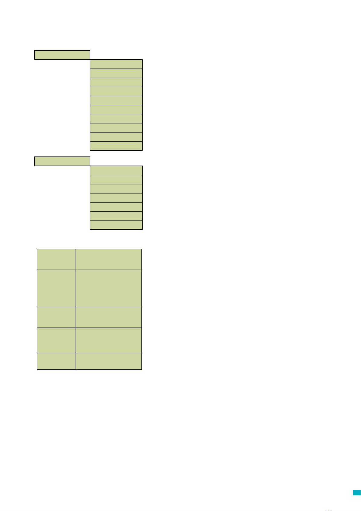
Quick Start Menu Process Guide
You have now nished the essential programming, If
you are in an option, press * to return to the Quick Start
Menu. Then, to exit programming mode Press * and
select the action required upon exiting from this list.
Scroll up
Scroll Down
Forward / Accept
Back / Cancel
The Avire Hub is our cloud platform
for monitoring Avire emergency
communication systems. Users
can set up and maintain their
own database of lift emergency
telephones and the Avire Hub will
receive emergency and test calls. The
Avire Hub can also remotely program
the telephone units, saving time and
money and reducing the number of
site visits required.
Please contact your local sales oce
for access to the Avire Hub.
www.avire-global.com
Avire Hub
Menu Controls
Step 1 Accessories +Select the accessories you have attached to
the unit by pressing # to select / deselect
each option
Step 2 Alarm No 1
+Using the keypad, enter the rst alarm
telephone number.
+Select the protocol required from the list
which includes Guided, Unguided, Memco,
P100 and Contact ID.
Step 3 Tech. No
+Using the keypad, enter the telephone
number of the software system for Technical
calls.
+Set to 03308088484 & P100 for Avire Hub. If
using Memcom with DCP, set parameter P035
to 03308088484 to enable Background calls
over data.
+Select the protocol required from the list.
+The unit will ask if you want to use the same
number for background calls, press # to
accept and * to reject.
Step 4 Background No.
+If you have accepted to copy the telephone
number from the Tech No, you can skip this
option.
+Set to 03308088484 & P100 for Avire Hub. If
using Memcom with DCP, set parameter P035
to 03308088484 to enable Background calls
over data.
+If not, enter the telephone number required
+Select the protocol required from the list
Step 5 Volume
+If you require a volume dierent to the
default volume, press the up and down
arrows until the desired volume is reached
+Press # to conrm
Step 6 Location
+To record a Location Message, press 2 to
start recording
+Press # to end the recording
+Press 1 to play the message back
Step 7 ID Code
+Only required when using Memco, P100 or
ContactID protocols. Default setting matches
the ID code printed on the unit label - should
only be changed if required to match an
older unit being replaced, or if a company-
specic numbering scheme is used.
Step 8 Network ID
+If you are attaching more than the one
Memcom unit to a single telephone line, you
need to assign each unit a network ID
+The rst unit would have an ID code of 1, the
second unit 2, the third unit 3 and so on.
Note: The quickstart menu also contains Step 9: Time and Step 10: Date
but these can be ignored if using the Memco protocol for background calls
(Memco protocol auto-syncs date and time with call centre).

66
Testing and Operating Mode
The status of the unit is shown on the top row of the idle
screen. If there are no faults, it will display ‘Status OK’.
1. Programming
Press 1 to access the standard programming menu.
Old Programming Mode – to program the Memcom+unit
using the Old Menu (code based) programming options,
simply press * followed by the passcode for the unit and
conrm by pressing # (default- *1234#) from the Idle
screen. A map of this menu is displayed on page 12 of this
document.
4. System Info
Displays the current system information for fault
diagnostics. Use the information shown in this section as
directed by the Avire Service Team if required.
5. Service Count
6. Fault Log
Displays information on all active faults – gives time and
date and fault mode.
Allows the alarm state to be reset. The message “7:End of
Alarm’ will ash on the top row of the idle screen until the
7 key is pressed to reset it.
Installation and essential programming are now complete,
please refer to Full Programming Options section on the
following pages of this guide if further programming is
required.
7. End of Alarm
Displays service count information if active.
2. Call Log
Displays the last 64 call events logged by the unit.
3. Event log
Displays the last 64 events for the unit.
*
Menu Controls
You can use the up and down arrow to navigate through
the options. Enter the option number to enter that option.
Fault Detected
If a fault is detected, then ’6: Fault Log’ will ash on the
top row of the idle screen as below. Press 6 to view the
fault log.
Alarm activated – End of Alarm
If the alarm state is activated i.e. an alarm call has been
placed. The unit will remain in alarm state until the ‘End of
Alarm’ is activated. Press 7 to end the alarm.
Menu Structure
Displays the current system information for fault
diagnostics
Scroll up
Scroll Down
Enter the option number required
Back / Cancel
Recent count is:
00000000
Service Due in:
00000500
Total Count is:
00000000
Overdue by:
00000042
6:Fault Log
1:Programming
7:End of Alarm
1:Programming
6:Fault Log
1:Programming
7:End of Alarm
1:Programming
Status OK
1:Programming
2:Call Log
3:Event log
4:System Info
5:Service Count
Status OK
1:Programming

77
Full Programming Options
Menu Sections
Tel. Numbers
Alarm no.
Up to four alarm telephone numbers can be programmed in the Memcom+
unit.
Using the keypad, enter the rst alarm telephone number.
When using a Hotline, enter the telephone number as 0. This is only required
if the Hotline option has not already been set in System Cong+, otherwise
the menu automatically displays the protocol list without the need to enter
any number.
Select a protocol required from Fig 1 (on the left), scroll to the preferred
protocol and press # to conrm.
Note: When connecting to a PBX/PABX, insert the number required to get
an outside line, followed by a pause (*), followed by the telephone number.
i.e.. 9*01344854000
If further alarm numbers are required, repeat this process for each alarm.
Tech. no.
The Memcom+can place Technical alert calls to signal faults with the system.
A Technical alert is a non-scheduled event e.g. from a Technical Input or low
battery with no main power.
All other diagnostics are checked during a scheduled Background Call (see
below). As standard this number is attempted the number of times indicated
by the 5th digit in Call Attempts (see below Call Attempts) screen before
waiting for the next technical alarm. If using the Avire Hub, set Tech no. to
03308088484 and select the P100 protocol. Use Memco protocol when
connecting via any other type of GSM or a landline.
Background no.
To set up the EN81-28 three day test call (background test call) programme
the required telephone number here. If using the Avire Hub, set Background
no. to 03308088484 and select the P100 protocol. Use Memco protocol
when connecting via any other type of GSM or a landline.
Guided Voice Unit will play a Guidance
Message (see page 10) to the
call centre when answering an
alarm call
Unguided
Voice No message is played when a
alarm call is answered.
NOTE: If ‘Auto Location’ has
been selected in ‘System
Cong+’ then the location
message WILL automatically
play at the start of the call.
Memco Protocol required if receiving
background test calls with the
Avire Hub or ETR.
P100 Protocol required if receiving
background test calls in the
Avire Hub. Can also be used
with other P100 compatible
software.
Contact ID Protocol required if receiving
background test calls with
‘Contact ID’ receiver software
Tel. Numbers >
Alarm no. 1
Alarm no. 2
Alarm no. 3
Alarm no. 4
Tech.no.
Background no.
Call attempts
Quickstart >
Accessories >
Alarm no.1
Tech.no.
Background no.
Volume
Location
ID Code
Network ID
Time
Date
Menu Sections
Quick Start
The quick start menu consists of 8 menu options required for quick setup.
Please refer to the previous page in this guide for more information.
Fig. 1
Call Attempts
The number of attempts the Memcom+ will make to contact each telephone
number (maximum is 9 attempts per number). The default is ‘999999’; each
digit identies one of the six programmed telephone numbers.

88
Full Programming Options
Accesories
Audio Setup >
Phone Line >
Menu Sections
Accessories
The Accessories section is divided into Audio Setup and Phone Line
sub-sections:
Audio Setup >
Multi-dial Sets the unit to call each of the programmed alarm numbers one after the other.
EN81-28 Mode Prevents the unit from accepting incoming calls when not in an alarm state and
requires a passcode to enter remote programming.
Consec. dial Changes the dialling sequence; all call attempts to the rst number are completed
before unit attempts to call the second number and so on.
Ext. mic. record Only use if directed by Avire Technical Support
Alt. dial tone Allows system to work with an intermittent dial tone.
TOC int. mic. This option activates the internal mic on the Memcom+unit during alarm calls form
the unit or during MPS calls. Required if the External Mic does not clearly pick up
speech from the TOC position.
Verbal c/down Units gives a verbal countdown until the emergency call is placed.
N/C alarm push Select option if connecting to a N/C alarm push contact
Service as alm Select option if connecting to an alarm push with voltage to connections 16 & 17
Passcode? Requires a passcode to be entered before accessing the ‘System Cong’ menu.
EOA Pictogram Sets the system to keep the alarm pictogram lit whilst the unit is in an alarm state.
Alarm Tone
- use ext.mic.
- Tech IP2
Sets the unit to emit a tone from the internal speaker when the alarm push is
pressed:
Note: these options should be used as directed by Avire
Int mic/spkr Select this option if the Memcom is not connected to any external
microphone or speaker.
External mic Select this option if the Memcom is connected to an external microphone.
COP Accessory Select this option if connecting the Memcom+to an Avire COP accessory
PSTN line Default setting - use for standard phone lines or GSM Gateways (except
for 452 00X)
452 002/003
Hotline
452 000 GSM
System Cong
Settings
ID Code
8 digit device code, will be transmitted at the beginning of calls to numbers
congured with P100 and Memco protocol.
Volume
Press the up and down arrows to adjust the volume and press # to conrm.
Settings >
ID Code
Volume
System Cong >
System Cong+ >
HW Monitoring >
Phone Line >

99
Auto Location xüWhen an operator answers an alarm call, the Memcom+will
automatically play the location message.
NOTE: when programming in the alarm numbers
‘UNGUIDED’ protocol must be selected (see section on Alarm
Numbers for more detail).
Avoid Silence xüDuring an alarm call the Memcom+will not mute its speaker,
unless the operator presses the ‘2’ key on their handset.
Quick Dial xüReduces the dial tone detection test from 7 seconds to 3
seconds – prevents issues with exchanges timing out after 4
seconds.
Quick VAD. xüAllows the Memcom+to detect speech before the rst ring
pulse has been sent down the line.
Dialtone req xüRequires the Memcom+to detect a dial tone before it attempts
to dial out.
Linet. Alert xüIf the phone line to the Memcom+is cut, the unit will play an
audible warning message. The message will repeat every 3
minutes unit the phone line is restored.
Hotline xüTells the Memcom it is connected to a hotline, allowing any
other of the call protocols to then be selected for use on that
line.
Menu Sections
System Cong+
Hardware (HW) Monitoring
Hardware monitoring sets which system elements are checked when
the unit completes its self-check and places a test call. Default
settings are shown below:
Full Programming Options
Power Supply ü
Battery ü
Phone Line ü
GSM low sig. û
GSM no sig. û
Spkr/mic. ü
GSM Status û

1010
Full Programming Options
Menu Sections
Lift Monitor
The lift monitor section allows you to detect faults from third party lift
monitoring devices connected to the technical inputs on the Memcom+unit.
When a fault is detected the Memcom+ will dial out and place a technical alert.
The Lift Monitor section is divided into Tech Inputs and Service Count:. There
are two options for technical inputs:
IP1 only – This is the default option which disables the second input. If a
third party device is connected to the Memcom+unit (connections 11 and 12),
the unit will dial out immediately when a fault is indicated by the third party
device.
IP1 + IP2 (Serv.) – Selecting this option allows customers to use the service
counter (connections 16 and 17) input as a second technical input.
Service Count
Memcom+can be connected to the lift controller (connections 16 and 17) to
track the number of operations the lift performs.
The Memcom+can then be programmed to place a Technical Alert after a set
number of operations (intervals). The Technical Alert will be placed with the
event message “Technical Alarm – Lift in service too long”. This can then be
used to determine when a lift may need to be serviced.
Lift Monitor >
Tech Inputs >
Service Count >
Tech Inputs IP1 only xü
IP1 + IP2 (Serv.) xü
Interval Set the number of operations you want the lift to perform before a Technical Alert is
placed by the Memcom+
Live Count This shows a live count of the operations that the lift has performed since the
controller was connected to the Memcom+.

1111
Full Programming Options
Messages
Delays >
COP delay
MPS delay
TOC delay
Tech IP1 delay
Tech IP2 delay
Hangup delay
Answer delay
AC fail delay
Filt.oride del
BGcall fail
Messages >
Location
Reassurance
Guidance
Menu Sections
Delays
The delays can be set to alter the length of the delay
before the unit places a call.
COP delay - How long (in seconds) each of the alarm
buttons, in the COP, needs to be pressed before an
emergency call is placed. Default is 3 seconds
MPS delay - ‘MPS’ refers to Multi Point Station
accessories (part number 492 021). How long (in
seconds) each of the alarm buttons, on the MPS units,
needs to be pressed before an emergency call is
placed. Default is 3 seconds.
TOC delays - how long (in seconds) the alarm button,
in the Memcom+unit (Top Of Car), needs to be pressed
before an emergency call is placed. Default is 3
seconds.
Tech IP1 delay - The delay before a technical call is
placed, upon receiving a fault signal from a connected
third party device using the Technical Input.
Tech IP2 delay - The delay before a technical call is
placed, upon receiving a fault signal from a connected
third party device using the Technical Input.
Hang up delay - sets time (in minutes) before Memcom+
hangs up a call (talk time).
Answer delay - the number of rings the Memcom+must
detect before answering any incoming calls. Where
multiple Memcom+are sharing a line, they must all have
the same Answer Delay set.
AC fail delay - the delay (in minutes) between a loss of
external power to the Memcom and the corresponding
technical call being placed. If the external power is
restored to the Memcom before the end of the delay
period, the call will be cancelled. Default is 0 minutes.
Filt.oride del - how long (seconds) COP alarm button
needs to be held down after standard COP delay
reached to override door ltering as required by EN81-
28:2018.
BGcall fail - how long (minutes) the Memcom will wait
after failed background call attempt before indicating
failure via pictograms as required by EN81-28:2018.
Location This is the only message that needs recording. The location message is
played to the call centre receiving the alarm call, to inform them of the
location of the lift.
Reassurance This is the message played to trapped passengers as an alarm call is
being placed.
Guidance If the ‘Guided’ protocol has been selected, this message will be played
to the call centre operator to ask them to select whether to listen to the
Location message or to be connected to the lift car immediately.

1212
Full Programming Options
Advanced Settings
Passcode
Enter the passcode required to enter standard programming mode
when EN81-28 mode is active. (up to 6-digits). This will also become
the passcode required to access the old menu structure. However,
from the idle screen you will have to press * PASSCODE #
Network ID
Set an extension number 1-8 where units share a phone line. All unit
IDs on a system need to be unique.
Next EN81 call
Details the next scheduled Background call for the unit.
PBX Frequency (Default 320)
Sets disconnect tone frequency (40-2000Hz in 40Hz steps), if
connected to a PBX which does not use standard tones.
Note: 640 is another commonly used PBX frequency.
Language
Set the language required by entering the following:
Note: Other languages may also be listed here.
Advanced >
Passcode
Network ID
Next EN81 call
PBX Frequency
Language >
Pri.rly.mode >
Pri.rly.o/ride >
GMT oset
DTMF RX
English ü
German û
French û
Italian. û
Spanish û
Time / Date >
Time
Date
Menu Sections
Time / Date
The time and date can be set by entering the correct values and
conrmed by pressing #

1313
Menu Sections
Relay Modes
The relay contact on a Memcom+ can be used to switch the power
supply to an external device. The following modes are available:
Pri.rly.mode
Siren û ü Relay contacts close when the Alarm Push is
activated, and open again after the alarm push delay.
Typically used to trigger a siren on the lift car.
Door (NO/CMD) û ü Door release mode, release on command, default
relay state is N/O: The door release is only activated
if the operator presses the ‘8’ key on their handset
during the initial alarm call or any follow-up calls. The
release will then remain activated until the call ends.
Door (NC/CMD) û ü Door release mode, release on command, default
relay state is N/C: The door release is only activated
if the operator presses the ‘8’ key on their handset
during the initial alarm call or any follow-up calls. The
release will then remain activated until the call ends.
Door (NO/ALM) û ü Door release mode, release on alarm push, default
relay state is N/O. The door release is activated
as soon as the Alarm Pictogram is lit, and remains
activated until the End of Alarm signal is received.
Door (NC/ALM) û ü Door release mode, release on alarm push, default
relay state is N/C. The door release is activated
as soon as the Alarm Pictogram is lit, and remains
activated until the End of Alarm signal is received.
PSTN fault û ü The relay contacts default to closed, and open
whenever a PSTN line fault is detected. When the
fault condition is cleared, the contacts return to the
default closed state.
GSM fault üThe relay contacts default to closed, and open
whenever a GSM fault is detected. When the fault
condition is cleared, the contacts return to the default
closed state.
Note: GSM monitoring must rst be setup under ‘HW
monitoring.
Tech. fault û ü Technical fault mode - The relay contacts default to
the closed state, opening whenever any technical
fault is detected by the Memcom+. Once the fault
condition has cleared, the contacts close again.
Emg. Lighting û ü Emergency lighting mode - the relay contacts default
to the open state, closing within 1 second of a loss
of external power. This allows the use of the relay to
switch backup power to emergency lighting hardware
during an external power failure. Once external power
is restored, the relay contacts open again.
Spk. Picto û ü If a dual illuminated alarm push is connected to the
relay contacts:
When the call centre answers an alarm call the relay
contact will close and trigger the illumination on the
alarm push; alarm push will remain lit until the call
centre ends the call.
Both Pictos û ü If a dual illuminated alarm push is connected to the
relay contacts:
When the alarm button is pressed the relay contact
will close triggering the illumination on the alarm
push; alarm push will remain lit until the call centre
ends the call.
Low battery û ü Defaults to holding the contacts closed, opening
them when a low battery state is detected.
Pri.rly.o/ride
None û ü
Enables the state of the primary relay contacts to
be overridden to open or close regardless of the
operation mode setting.
Open û ü
Closed û ü
Full Programming Options
GMT Oset
For reference only; will not need updating on the unit.
DTMF RX
Use only if directed by Avire Technical Support.

1414
Troubleshooting
Wiring
GSM
Telephone Line
Problem Solution
“No Dial Tone” showing on LCD 1. Disconnect Green Terminal Block and check voltage across Terminals 1 & 2 [24vdc-60vdc
dependent on the type of line used].
2. If no voltage is present, check the telephone socket and the travelling spares/ex used.
“Number is not Recognised”
is heard coming from the
Memcom+?
1. This is a BT Automated Message. Check the number/numbers are correct.
2. If you have a handset, connect it and check the telephone line.
3. If a PBX / PABX is used in the building insert the number required to get an outside line, in
front of the telephone number/s you enter in the unit.
4. 0800 telephone numbers do not work with emergency telephones.
It does not matter which number
is programmed into the unit, it
always dials the same number
1. If you have a Handset, check the telephone line. Lift the handset, and if the line is ringing
before any keys are pressed – it means the telephone line is a Hotline.
2. If test shows the line is a hotline, follow the programming options earlier to set up the
Memcom for Hotline operation.
Unit is working on the telephone
line, but dialling in is not possible
1. Enter the value 1 in Delays> Answer Delay, and check using a handset that the telephone line
can be dialled from an external telephone number. Change Delays> Answer Delay back to 2 after
test.
2. In the Hardware> System Cong option, check that EN81-28 Mode is de-selected.
Problem Solution
Only have one set of contacts on
the Alarm Push, these set o the
Alarm & Siren
1. Remove the two wires from the Alarm Push and wire directly to Terminals 5&6, then wire two
spares from Terminals 9&15 to the back of the Alarm Push.
Alarm Push button is not working 1. It may be that the Alarm Push button has not been pressed for long enough. Check Delays> In
Car Delay to see what delay has been set. The default is 3 seconds. Adjust accordingly, but do
not set as 0.
2. Check that the Alarm Push is wired to connections 9&15 without voltage.
3. Check if the circuit is N/O or N/C. If normally closed, in Settings> System Cong, select N/C
Alarm Push.
4. Place a Short/Wire Link across Terminals 9&15 –This should trigger the Memcom+alarm, if it
does, then the problem is with the alarm push or the wiring.
The sound quality of two-way
communication is poor
1. Check what the volume has been set to and adjust up or down accordingly.
2. If sound quality issues continue, consider changing the location of the Memcom+unit, ensure
the microphone postioned in a suitbale positon and not located near VF signals.
3. If problems still persist, then it may be worth considering a COP speaker / mic accessory.
Please contact us for more information.
Problem Solution
GSM unit is not working correctly
or is not recognized by the
Memcom+Unit
1. Check the SIM card used in a mobile phone, and ensure that the correct SIM card PIN number
has been entered in Advanced> SIM PIN
2. If necessary, deactivate the SIM Card PIN number and the Mailbox.
3. Once GSM has been set up correctly, disconnect it, then reconnect it to the Memcom+unit.

1515
Troubleshooting
Power
COP Accessories
Problem Solution
How do you power down the
battery?
1. Disconnect the power from the unit.
2. When the LCD display shows ‘Power turned o’, press and hold the # button.
LCD Display showing low o/p
battery
1. Memcom+needs to be left on overnight to charge the battery.
2. In operation, the Memcom+unit must be connected to a permanent power supply, which
should not be switched o, except in an emergency.
Memcom+switches o after a
short period
1. Make sure the power is correctly connected.
2. If the power is not connected correctly, Memcom+could be using battery power and switching
of when the battery runs out of power.
LCD Display is blank when
powered up
1. Check the voltage of connections.
Unit shows battery low 1. Check mains or DC supply
2. Check if the power circuit is in ‘power save’/’eco mode’
Problem Solution
Sound quality from the COP
accessory tted is poor or the
accessory is not functioning
correctly
1. Check that in Setting> Accessories, that COP Accessory is selected.
2. This will automatically drop the volume setting to the minimum, as this is the optimum level
when a COP accessory is connected.
3. If the volume is manually adjusted and is too high, this will cause feedback.
The LCD display on the unit
shows Mic/Speaker fault
1. Check the connection to the external microphone.
2. Power down the unit by disconnecting the power and pressing and holding down the # key.
Re-connect the power to power the unit back up.
Poor voice quality on the
Memcom+Unit
1. Check the volume level. This may need reducing if you are getting feedback issues.
External Microphone not
working?
1. Remove cover and check Microphone connection.
2. In Settings> System Cong, select the TOC int. mic. If two-way communication is achieved, this
shows that there may be a fault with the External microphone. In this case, send the unit back to
Avire for further testing.
Battery Information
Battery Specication
• 12V, 0.8Ah, Lead Acid battery
• Only use Avire batteries with the Memcom+Emergency Telephone (battery part number 450 880-04)
Replacing the Battery
1. Disconnect the power from the Memcom+, wait 5 seconds and then press and hold the # key to power down the unit
completely
2. Remove the top cover of the Memcom+by unscrewing the ve retaining screws
3. The battery is held in place by hook and loop tape; carefully remove the battery from the Memcom+housing and
disconnect the battery cable from the two-pin connector beneath the Memcom+ keypad*. Do not remove the keypad
as the connector can be accessed with the keypad in place
4. Connect the cable of the new battery to the two-pin connector beneath the Memcom+keypad (the connector can
only be connected in the correct orientation) and secure the new battery in the Memcom+housing using the hook and
loop tape provided
5. Replace the top cover of the Memcom+
6. Reconnect the power to the Memcom+
* IMPORTANT: Always ensure the proper disposal of batteries, in line with local regulations

1616
Old Programming Mode
The old programming menu is still available on the Memcom+unit. To access this mode of programming, from the idle screen, simply enter the
old programming passcode (default- *1234#). The old method of programming can also be used remotely, by dialing the phone number of the
Memcom, and following the same instructions.
Old Menu Structure Quick Start Guide to programming…
Programming options for the type of Memcom+Alarm / Software Calls
*11 1st (Alarm Tel Number) # Program 1st Alarm Number
*15 5th (telephone alarm number) **1# Program Technical Alarm Number
*16 6th (telephone alarm number) **1# Program EN81-28 Background Test Call Number
Sux Protocol
# Guided message for call centre
**0# No guided message for call centre.
**1# Memco Protocol - compatible with Avire Hub, Memcom ETR Software or
GlobalNet
**3# P100 Protocol - Recommended for Avire Hub.
**4# Alternative to # for use when Memcom is congured for Hotline operation.
**6# Contact ID Protocol
*23 Volume TOC 5, COP 0 Adjustable between 0-9 (0 = minimum setting)
*41 Location message: 1: Play Location 2: Record Location Message
*26 Hardware
Defaults: 12 TOC Version 8 COP Version
1 = EN81-28 operating mode opts
2 = Service Input = Tech.2
4 = Disable internal microphone
8 = Consecutive dial mode
16 = Enable Memcom+GSM module
64 = Alarm Input N/C
128 = Czech, Greek, Italian and Singaporean
dial tone cadences for use with multiple
Memcom+only
256 = Service Input as Alarm Activation
512 = COP Accessory attached (450 200 & 450
250).
Any combination can be programmed. Enter
sum of the numbers of the options required.
*27 Hardware Monitoring
Default: 39
1 = PSU monitoring
2 = Battery supply
4 = Phone line, (Do not use if
connected to a hotline)
8 = GSM Low signal
16 = GSM No signal
32 = Microphone/speaker test
64 = Power Logging
Any combination can be
programmed. Enter sum of the
numbers of the options required.
Exiting Programming
Press # to return to programming home screen, then enter one of the following exit
codes...
*01# Exit programming without making an alarm call
*03# Exit programming and call Alarm number 6 EN81-28
*021# Exit programming and call Alarm number 1 only
*035# Exit programming and call Alarm Number 5 Technical Alarm
*94 Total Count
*93 Due in Count
*92 Service Count
*91 Model/HW/SW
*90 GSM Signal
*84 EOA
*83 Not in Use
*82 Relay o/ride
*81 GSM SIM Pin
*61 Language
*52 Service Count
*51 Serv. Interval
*43 Guidance
*42 Reassurance
*41 Location
*40 Relay Mode
*39 PBX Freq.
*38 Hangup delay
*37 Test Call on
*36 Tech 2 Delay
*35 Tech 1 Delay
*34 TopOfCar Dly
*33 MPS Delay
*32 Answer Delay
*31 In-Car Delay
*29 GMT Oset
*28 Network ID
*27 Hardware Mon.
*26 Hardware Opts
*25 Set Date
*24 Set Time
*23 Speaker Vol.
*22 Password
*21 ID Code
*17 Dial Attempts
*16 Background
*15 Tech Alm
*14 Alarm No4
*13 Alarm No3
*12 Alarm No2
*11 Alarm No1
Memcom IG V03 (ML) \EP 12/08/2021
Memco is a brand of Avire
Avire Trading Ltd
Unit 1, The Switchback
Gardner Road
Maidenhead
Berkshire SL6 7RJ, UK
T: 01628 540100
E: sales.uk@avire-global.com
W: www.avire-global.com
If you require any further assistance when programming the Memcom+unit, please call our Technical Service Team on
01628 540160.

17
Memcom+Notruftelefon
Einbauanleitung
Ref Nr. 453 900 (ML) DE Version 3
System-Komponenten
Kabelgehäuse
Klemmenleiste
Memcom+ Gerät
Externes Mikrofon

18
TOC – (Top Of Car) Gerät für Aufzugdach 453 211
COP (Car Operating Panel) - Gerät für das
Bedienfeld der Fahrkabine 453 200/201
1. Installieren Sie das Memcom+mit den mitgelieferten
Schrauben auf dem Aufzugdach. Die Gummifüße dürfen
nicht entfernt werden, da ansonsten Rückkopplungen
auftreten können.
2. Schließen Sie die Telefonleitung, den Alarmknopf des
Aufzugs und sämtliches erforderliches Zubehör an, wie in
den Schaltplänen auf Seite 4 dieser Anleitung gezeigt.
3. Das externe Mikrofon des Memcom+TOC 4m muss im
Bedienfeld oder an einem hohen Punkt der Fahrkabine,
wie etwa in einer abgehängten Decke oder einem
Luftschacht, angebracht werden. Eventuell muss die
optimale Position des Mikrofons per Versuch ermittelt
werden.
4. Schließen vor dem Verbinden mit 90-230VAC immer
zuerst die Erde an.
Bei 24VDC-Betrieb ist keine Erde erforderlich. Verbinden
Sie zuerst den 0VDC-Anschluss, wenn die 24VDC-
Versorgung nicht abgeschaltet ist.
1. Installieren Sie das Memcom+zunächst an der Rückseite
des Bedienfelds der Fahrkabine.
2. Schließen Sie die Telefonleitung, den Alarmknopf des
Aufzugs und sämtliches erforderliches Zubehör an.
3. Bei 24VDC-Betrieb ist keine Erde erforderlich. Verbinden
Sie zuerst den 0VDC-Anschluss, wenn die 24VDC-
Versorgung nicht abgeschaltet ist.
Installation

19
Installation
Schaltplan
Anschluss an ein proprietäres System?
Ob Sie das Memcom+an einen Alarmknopf oder an Piktogramme eines bereits installierten Aufzugs anschließen oder in ein Aufzugsüberwachungs-System integrieren möchten, wir
können helfen. Wir haben Schaltpläne, die erklären, wie das Gerät in bestehende Verkabelungen eingeschleift wird. Ein geschultes Techniker-Team sorgt dafür, dass die Installation
klar und einfach ist.
Die Farben der Telefonkabel
können je nach Standort
unterschiedlich sein. Ziehen Sie
den jeweiligen Schaltplan vor
Ort zu Rate.
MPS-Stationen (492 021) werden parallel geschaltet
0V 0V 0V
Alarmlicht Sprechen Licht Alarmknopf
Alarmende
(Voreinstellung) N/O
* nicht erforderlich für
453 001 24VDC TOC
453 000 24VDC nur COP
453 010 24VDC nur COP
0V
PSTN (GSM Tip)
PSTN (GSM Ring)
MPS
MPS
Sirene (Relais)
Sirene (Relais)
Alarm Piktogramm (+)
Sprechen Piktogramm (+)
Alarmknopf
Alarmende
Common/technischer Eingang 1
Aufzugsstatus (5-24VDC)/technischer Eingang 1
24VDC
0VDC
Servicezähler (+)/technischer Eingang 2
Servicezähler (-)/technischer Eingang 2
230VAC Außenleiter
Türlter (5-24VDC)
230VAC Neutralleiter
Earth
Türlter
Aufzugsstatus
90-230VAC* Eingang
Servicezähler
12-230VAC/DC
24VDC Eingang
5-24VDC Eingang
Common Eingang
12 & 13
Stromversorgung für
externe Sirene
Voreinstellung N/O

20
Stecker für
externes
Mikrofon
Stecker für
externen
Lautsprecher
Stecker für
induktive
Schleife
RS232 Stecker
12VDC Ausgang
Installation
This manual suits for next models
2
Table of contents
Languages:
Other AVIRE Emergency Phone manuals