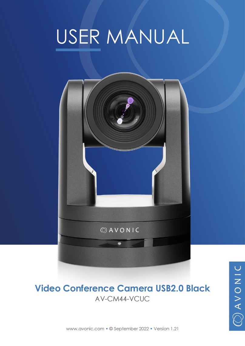
Avonic AV-CM44-VCUC-B User manual

2
www.avonic.eu 2
CONTENTS
Introduction............................................................................................................................. 4
Contact. .. .. .. .. .. .. .. .. .. .. .. .. .. .. .. .. .. .. .. .. .. .. .. .. .. .. .. .. .. .. .. .. .. .. .. .. .. .. .. .. .. .. .. .. .. .. .. .. .. .. .. .. .. .. .. .. 4
Join Avonic .. .. .. .. .. .. .. .. .. .. .. .. .. .. .. .. .. .. .. .. .. .. .. .. .. .. .. .. .. .. .. .. .. .. .. .. .. .. .. .. .. .. .. .. .. .. .. .. .. .. .. .. .. .. 4
Safety Notes .. .. .. .. .. .. .. .. .. .. .. .. .. .. .. .. .. .. .. .. .. .. .. .. .. .. .. .. .. .. .. .. .. .. .. .. .. .. .. .. .. .. .. .. .. .. .. .. .. .. .. .. .. 4
Package contents and Accessories ...................................................................... 5
Contents.. .. .. .. .. .. .. .. .. .. .. .. .. .. .. .. .. .. .. .. .. .. .. .. .. .. .. .. .. .. .. .. .. .. .. .. .. .. .. .. .. .. .. .. .. .. .. .. .. .. .. .. .. .. .. .. 5
Handling precautions .. .. .. .. .. .. .. .. .. .. .. .. .. .. .. .. .. .. .. .. .. .. .. .. .. .. .. .. .. .. .. .. .. .. .. .. .. .. .. .. .. .. .. .. .. .. 5
Accessoiries .. .. .. .. .. .. .. .. .. .. .. .. .. .. .. .. .. .. .. .. .. .. .. .. .. .. .. .. .. .. .. .. .. .. .. .. .. .. .. .. .. .. .. .. .. .. .. .. .. .. .. .. .. 5
Product Overview................................................................................................................ 6
Features .. .. .. .. .. .. .. .. .. .. .. .. .. .. .. .. .. .. .. .. .. .. .. .. .. .. .. .. .. .. .. .. .. .. .. .. .. .. .. .. .. .. .. .. .. .. .. .. .. .. .. .. .. .. .. .. 6
Installation ............................................................................................................................... 7
Connections .. .. .. .. .. .. .. .. .. .. .. .. .. .. .. .. .. .. .. .. .. .. .. .. .. .. .. .. .. .. .. .. .. .. .. .. .. .. .. .. .. .. .. .. .. .. .. .. .. .. .. .. .. 7
System Select Switch. .. .. .. .. .. .. .. .. .. .. .. .. .. .. .. .. .. .. .. .. .. .. .. .. .. .. .. .. .. .. .. .. .. .. .. .. .. .. .. .. .. .. .. .. .. .. 8
RS232 Interface.. .. .. .. .. .. .. .. .. .. .. .. .. .. .. .. .. .. .. .. .. .. .. .. .. .. .. .. .. .. .. .. .. .. .. .. .. .. .. .. .. .. .. .. .. .. .. .. .. .. .. 8
RS232 network connection diagram .. .. .. .. .. .. .. .. .. .. .. .. .. .. .. .. .. .. .. .. .. .. .. .. .. .. .. .. .. .. .. .. .. .. .. 9
RS485 network connection diagram .. .. .. .. .. .. .. .. .. .. .. .. .. .. .. .. .. .. .. .. .. .. .. .. .. .. .. .. .. .. .. .. .. .. .. 9
IP network connection diagram. .. .. .. .. .. .. .. .. .. .. .. .. .. .. .. .. .. .. .. .. .. .. .. .. .. .. .. .. .. .. .. .. .. .. .. .. .. .. 9
Serial Communication Control .. .. .. .. .. .. .. .. .. .. .. .. .. .. .. .. .. .. .. .. .. .. .. .. .. .. .. .. .. .. .. .. .. .. .. .. .. .. .. 10
Operation.................................................................................................................................. 11
Remote controller .. .. .. .. .. .. .. .. .. .. .. .. .. .. .. .. .. .. .. .. .. .. .. .. .. .. .. .. .. .. .. .. .. .. .. .. .. .. .. .. .. .. .. .. .. .. .. .. .. 11
Other Key Combinations . .. .. .. .. .. .. .. .. .. .. .. .. .. .. .. .. .. .. .. .. .. .. .. .. .. .. .. .. .. .. .. .. .. .. .. .. .. .. .. .. .. .. .. 13
OSD Menu ................................................................................................................................. 14
WebGUI. .. .. .. .. .. .. .. .. .. .. .. .. .. .. .. .. .. .. .. .. .. .. .. .. .. .. .. .. .. .. .. .. .. .. .. .. .. .. .. .. .. .. .. .. .. .. .. .. .. .. .. .. .. .. .. .. 19
Maintenance .......................................................................................................................... 22
Camera Maintenance . .. .. .. .. .. .. .. .. .. .. .. .. .. .. .. .. .. .. .. .. .. .. .. .. .. .. .. .. .. .. .. .. .. .. .. .. .. .. .. .. .. .. .. .. .. 22
Unauthorized Use .. .. .. .. .. .. .. .. .. .. .. .. .. .. .. .. .. .. .. .. .. .. .. .. .. .. .. .. .. .. .. .. .. .. .. .. .. .. .. .. .. .. .. .. .. .. .. .. .. 22
Troubleshooting................................................................................................................... 22
General Advice .. .. .. .. .. .. .. .. .. .. .. .. .. .. .. .. .. .. .. .. .. .. .. .. .. .. .. .. .. .. .. .. .. .. .. .. .. .. .. .. .. .. .. .. .. .. .. .. .. .. .. 22
Power Issues.. .. .. .. .. .. .. .. .. .. .. .. .. .. .. .. .. .. .. .. .. .. .. .. .. .. .. .. .. .. .. .. .. .. .. .. .. .. .. .. .. .. .. .. .. .. .. .. .. .. .. .. .. 22
Image.. .. .. .. .. .. .. .. .. .. .. .. .. .. .. .. .. .. .. .. .. .. .. .. .. .. .. .. .. .. .. .. .. .. .. .. .. .. .. .. .. .. .. .. .. .. .. .. .. .. .. .. .. .. .. .. .. .. 23
Control . .. .. .. .. .. .. .. .. .. .. .. .. .. .. .. .. .. .. .. .. .. .. .. .. .. .. .. .. .. .. .. .. .. .. .. .. .. .. .. .. .. .. .. .. .. .. .. .. .. .. .. .. .. .. .. .. 23
WebGUI. .. .. .. .. .. .. .. .. .. .. .. .. .. .. .. .. .. .. .. .. .. .. .. .. .. .. .. .. .. .. .. .. .. .. .. .. .. .. .. .. .. .. .. .. .. .. .. .. .. .. .. .. .. .. .. .. 23
Visca over Serial properties......................................................................................... 24
3
www.avonic.eu 3
Visca over IP properties and command list..................................................... 24
Pelco-D Protocol Command List.............................................................................. 34
Pelco-P Protocol Command List............................................................................... 35
Appendix B Dimensions.................................................................................................. 36

www.avonic.eu Back to top 4
• Installation and servicing should only be done by Qualified Service Personnel and conform to all
local codes.
• This unit is designed for indoor use only and it must not be installed where exposed to water or
other liquids and moisture.
• Before powering on the device, check the input power voltage carefully.
• Avoid shock and vibration when transporting and installing the device.
• Electronic devices produce heat. Do not block the ventilation slots of the device and make sure
the installation environment is well ventilated to avoid overheating.
• Before cleaning, unplug the power cable. Use a soft, damp cloth to clean the device, do not use
strong or abrasive detergent to clean that will damage the device.
• If you wish to dispose this product, please contact Avonic to obtain info about the disposal
procedure.
facebook.com/avonicPTZ linkedin.com/company/avonic twitter.com/avonic
For any questions or suggestions, contact your reseller or the local distributor of Avonic. Find the local
distributor on the website of Avonic. For the most recent version of the manual or datasheet, look at the
Avonic website: www.avonic.eu
Thank you for your Avonic purchase. Before beginning to operate this device, please read the manual in
order to make sure the best performance is obtained. Save this manual for future reference.
Join Avonic
Safety Notes
Contact
INTRODUCTION

www.avonic.eu 5
Back to top
Be cautious to hold the camera by
its base. When placing back the ca-
mera in its protective foam, be sure
the lens is in horizontal position.
Wall and Ceiling mount
SKU white: AV-MT200-W
SKU black: AV-MT200-B
Wall mount
SKU white: CM-WMW
SKU black: CM-WMB
Ceiling mount
SKU white: CM-CMW
SKU black: CM-CMB
Quantity Description Avonic SKU
1 pc PTZ Camera AV-CM44-VCUC
1 pc Power Supply 12V/A AV-CM40-PSU
1 pc Remote Control AV-CM40-RC
1 pc RS232 9-pin male to 8-pin male AV-CM-RS232
1 pc USB cable type A to type A AV-USB20-AA
Accessoiries
Handling precautions
Contents
PACKAGE CONTENTS AND ACCESSORIES

6
www.avonic.euBack to top
• high-quality 1/2.8 inch, 2.07 million effective pixels high-quality HD CMOS sensor to
achieve maximum Full HD 1920 x 1080 resolution.
• The output frame rate is up to 30fps in 1080P
• 5x Optical Zoom, glass lens.
• Using the RS232, RS 485 or RJ45 interface, all the parameters of the camera can be
remotely controlled.
• Leading autofocus algorithm for a fast, accurate and stable auto-focusing lens.
• Low noise and High SNR: Low Noise CMOS effectively ensures high SNR of the camera.
• Advanced 2D/3D noise reduction technology to reduce picture noise while ensuring
accurate sharpness.
• Quiet, fast and smooth PTZ due to a high accuracy step driving motor mechanism.
• Auto-Flip function
• Low-power sleep function: the consumption is less than 500mW in standby mode.
• Supports Multiple Control Protocols: VISCA, VISCA over IP, PELCO-D, PELCO-P protocols
which can also be automatically recognized.
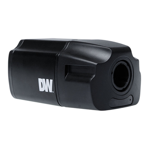
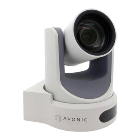
The Avonic AV-CM44-VCUC is a high-quality PTZ camera, with USB2.0 output. The camera is
designed for fixed installations and works very well in low light conditions. The camera is equipped
with high quality components like a Panasonic CMOS sensor and a glass lens with 5x optical
zoom. Control the camera over RS232 or RS485 with any controller with VISCA or PELCO support.
Features
PRODUCT OVERVIEW

7
www.avonic.euBack to top
1. RS-485 two-wire serial communication with 2-pin Phoenix connector
2. System Selector (see Installation for more details)
3. RS-232 mini-DIN-8 IN (connect the supplied RS-232 cable)
4. RS-232 mini-DIN-8 OUT for daisy chaining RS-232 connection
5. USB2.0 Type A, UVC video output
6. RJ45 Ethernet connection for IP control or firmware update
7. DC12V power with locking screw (connect the supplied DC PSU)
8. Power ON/OFF
Connections
INSTALLATION
1
5 6 7 8
2 3 4

8
Back to topBack to top www.avonic.eu
CAUTION:
The System Select Switch has no function in the AV-CM44-VCUC as all the output resolutions are
dictated by the computer to which it has been connected
Power adapter
This equipment is equipped with a 12V/2A DC power supply. Insert the power supply according to the requi-
rements, turn on the power switch.
Power On
Pan-Tilt will rotate to the maximum position of top right after the camera started, then it returns to the
center, the process of initialization is finished. The camera will show its current IR-channel setting and IP
Address on the osd (Note: If the position preset 0 has been stored, the position preset 0 will be called after
initialization). From this point onwards the user can control the camera with the supplied IR remote control,
Serial control using RS232/RS485 or over IP using Visca over IP
RS232 Interface
System Select Switch

9
Back to topBack to top www.avonic.eu
When connecting multiple cameras through RS-232, use daisy chaining network architecture. Max cable
length for RS-232 is 10-15m.
To connect multiple cameras by RS485, the cameras are attached to a 2-wire twisted pair bus (max length
1200m) that is terminated at both ends with a 120 Ω impedance resistor. The maximum distance from the bus to
the camera or controller is 5m.
RS232 network connection diagram
RS485 network connection diagram
Controller Camera
In Out
RS-232 RS-232 RS-232
In Out In Out
Camera Camera
Connect an Avonic camera to a LAN using a standard switch
Addressing is done via IP, the Visca address in a Visca over ip environment is always 1.
IP network connection diagram
IP controller
Ethernet
Ethernet
Ethernet
Lan Switch
PC
Camera

10
www.avonic.euBack to top
COM port settings
In default working mode, an Avonic camera is able to connect to a VISCA controller with RS-232 or RS-485
serial interface.
The camera can be controlled via RS-232, the parameters of RS-232C are as follows:
• Baud rate: 2400/4800/9600/115200
• Start bit: 1 bit.
• Data bit: 8 bits.
• Stop bit: 1 bit.
• Parity bit: none.
The camera can be controlled via RS-485, Half-duplex mode. The parameters are:
• Baud rate: 2400/4800/9600
• Start bit: 1 bit.
• Data bit: 8 bits.
• Stop bit: 1 bit.
• Parity bit: none.
Serial Communication Control

11
www.avonic.euBack to top
a. Set
b. Power
c. Camera select
d. Number Keys
e. Focus + -
f. Auto/Manual Focus
g. Zoom + -
h. Set & Clear Preset
i. PTZ keys (up/down/left/right)
j. Home
k. BLC (Back Light Control) ON/OFF
l. Menu
m. Function Keys (F1/F2/F3/F4)
n. Blank buttons
Remote controller
OPERATION

12
www.avonic.euBack to top
a. Set
This button has no function with this camera.
b. Power
Press the power button to turn on the camera. If the position preset 0 has been stored, the position preset 0
will be called up after initialization. Press the power button again to turn the camera off, it will turn to the back
when turned off, this is called the “privacy mode”.
c. Camera select
Up to 4 different cameras can be controlled with 1 IR remote Control. With the camera select buttons (1,2,3,4)
you can select the IR channel the remote control is using. The default camera IR channel is 1.
To control a camera on first use, please select camera 1 (IR channel 1) on the remote control. To control a
second camera you first need to change the IR channel stored in the camera from 1 to 2.
• First turn off the other camera’s in the room you don’t want to change, to prevent
that other camera’s also get changed accidentally.
• Select camera 1 on the remote control, because the camera is still configured to
listen to IR channel 1.
• Press [*]+[#]+[F2] to change the IR channel inside the camera to IR channel 2
• Select camera 2 on the remote control and see if the camera responds to the remote
control.
Key Combinations: (Default IR address is 1)
[*]+[#]+[F1] : Camera Address No. 1 [*]+[#]+[F3] : Camera Address No. 3
[*]+[#]+[F2] : Camera Address No. 2 [*]+[#]+[F4] : Camera Address No. 4
d. Number Keys
The number keys are used to call presets. Press the number of the preset desired and the camera will res-
pond accordingly (See ‘h’ on how to set & clear presets)
e. Focus + -
Push the button “manual focus” first before using the focus buttons. Focus the camera with the + and – but-
ton. If the camera does not respond check if the camera is set to auto-focus.
f. Auto/Manual Focus
Set the camera in auto-focus or manual-focus. If the camera is configured to auto-focus the buttons “Focus
+ -“ are disabled. When the camera is in “manual focus” modus and the Zoom buttons are used, the camera
automatically switces to auto-focus.
g. Zoom + -
Zoom the camera with these buttons. When the camera is in “manual focus” modus and the Zoom buttons
are used, the camera automatically switches to auto-focus.
h. Set & Clear Preset
A preset is a specific position of a camera that you save into the camera. A preset is assigned to a number
from 0-9. To set a preset first point the camera in a specific directing and a specific zoom position. Now as-
sign the position to a number with the button “Set Preset”. You can call the preset by pressing the number 0-9
on the remote control.
Set Preset: [SET PRESET]+[<number>]
Call Preset: [<number>]
Clear Preset: [CLEAR PRESET]+[<number>]
If the position preset 0 has been stored, this position will be called after initialization.

13
www.avonic.euBack to top
i. PTZ keys (up/down/left/right)
Move the camera in a direction.
j. Home
Set the direction of the camera to a center position.
k. BLC (Back Light Control) ON/OFF
Change the Back light control setting.
l. Menu
The Menu button opens the “On Screen Display (OSD)” menu. This menu is visible on the USB output. If the
menu is not in English, please press [*]+[#]+[4] to change the Menu language to English.
m. Function Keys (F1/F2/F3/F4)
Used to configure the IR channel of the camera. See [c. Camera select] above for instructions.
n. Blank buttons
These buttons have no function with this camera.
[*]+[#]+[4] : Menu set to English
[*]+[#]+[6] : Restore factory defaults
[*]+[#]+[9] : Flip switch (just temporary flip to view the image flipped)
[*]+[#]+[Auto] : Enter into the aging mode, only for quality control purposes
[*]+[#]+[Manual] : Restore the default username, password, and IP address
[#]+[#]+[#] : Clear all presets
Other Key Combinations

14
www.avonic.euBack to top
The OSD menu can be accessed by the
Remote Control or an Avonic PTZ controller.
In the following pages, the navigating is
described for using the IR Remote Control.
Language
Setup Protocol
Visca Address
Visca Address Fix
Pelco-P Address
Pelco-D Address
Baudrate
Camera Exposure Mode
EV
BLC
Flicker
G. Limit
DRC
Color WB Mode
RG Tuning
BG Tuning
Saturation
Hue
AWB Sensitivity
Image Brightness
Contrast
Sharpness
Flip-H
Flip-V
Gamma
DZoom
DCI
Focus Focus Mode
AF-Zone
AF-Sensitivity
Noise Reduction NR-2D
NR-3D
Dynamic Hot Pixel
Style
P/T/Z
Video Format
Network Settings
Version
Root menu
Restore Default
DHCP ON/OFF
OSD MENU

15
www.avonic.euBack to top
1. MENU
Press [MENU] button to display the main menu on the screen. Use the arrow buttons to move the cursor to
the item to be set. Press the [HOME] button to enter the corresponding sub-menu. Press [
2. SETUP
3. CAMERA
MENU
Language EN / CN
Setup
Camera
P/T/Z
Version
Restore Default
Select Item
Change Value
[Home] Enter
[Menu] Exit
SETUP
Protocol AUTO / VISCA / PELCO-D / PELCO-P
Visca Address 1 ~ 7
Visca Address Fix ON / OFF
PELCO-P Address 1 ~ 255
PELCO-D Address 1 ~ 255
Baudrate 2400 / 4800 / 9600 / 115200 / 38400
Select Item
Change Value
[Menu] Back
CAMERA
Exposure
Color
Image
Focus
Noise Reduction
Style Soft / Default / Normal / Clarity / Bright
Select Item
Change Value
[Menu] Back

16
www.avonic.euBack to top
3.1 EXPOSURE
3.2 COLOR
EXPOSURE
Mode Auto / Manual / SAE / AAE / Bright
Iris F11 ~ F1.8 / CLOSE
Shutter 1/25 ~ 1/10000
EV ON / OFF
EV Level -7 ~ +7
BLC ON / OFF
Flicker 50Hz / 60Hz / OFF
G. Limit 0 ~ 15
DRC 1 ~ 8 / CLOSE
Select Item
Change Value
[Menu] Back
COLOR
WB Mode Auto / 3000K / 4000K / 5000K / 6000K / 7000K / Manual / OnePush
RG Tuning -10 ~ 10
BG Tuning -10 ~ 10
RG 0 ~ 255
BG 0 ~ 255
Saturation 60% - 200%
Hue 0 ~ 14
AWB Sensitivity Low / Middle / High
Select Item
Change Value
[Menu] Back

17
www.avonic.euBack to top
3.3 IMAGE
The Flip function can be set, althoug the camera has an automatically flip function.
3.4 FOCUS
3.5 NOISE REDUCTION
IMAGE
Brightness 0 ~ 14
Contrast 0 ~ 14
Sharpness 0 ~ 15
Flip-H ON / OFF
Flip-V ON / OFF
B&W-Mode Color / B&W
Gamma 0.45 / 0.50 / 0.55 / 0.63 / Default
DZoom ON / OFF
DCI 1 ~ 8 / Close
Select Item
Change Value
[Menu] Back
FOCUS
Focus Mode Auto / Manual / OnePush
AF-Zone Top / Center / Bottom / All
AF-Sensitivity Low / Middle / High
Select Item
Change Value
[Menu] Back
NOISE REDUCTION
NR-2D 1 ~ 7 / Auto / OFF
NR-3D 1 ~ 8 / OFF
Dynamic Hot Pixel 1 ~ 5 / OFF
Select Item
Change Value
[Menu] Back

18
www.avonic.euBack to top
4. PTZ
7. RESTORE DEFAULT
6. VERSION
PTZ
Speed by Zoom ON / OFF
Zoom Speed 1 ~ 8
Image Freezing ON / OFF
Acc Curve Slow / Fast
Select Item
Change Value
[Menu] Back
RESTORE DEFAULT
Restore default? NO / YES
Select Item
Change Value
[Menu] Back
[Home] OK
VERSION
MCU Version nr date
Camera Version nr date
AF Version nr date
[Menu] Back
5. NETWORK
NETWORK SETTING
DHCP ON/ OFF
IP Address xxx.xxx.xxx.xxx
[Menu] Back

19
www.avonic.euBack to top
The camera is equipped with a limited WebGUI to setup minimal functionality to perform a firmware up-
grade.
Login
The default IP address is: 192.168.5.163
The default username is : admin
The default password is : admin
The login screen looks like this:
System
In the System Tab it is possible to change username and password, perform a firmware upgrade, reset
the camera to Default settings and Reboot the camera.
WebGUI

20
www.avonic.euBack to top
Update
The update form gives information on the current firmware versions and the possibility to update the firm-
ware by choosing an upgrade file provided by Avonic. Do not turn off the camera while updating.
Network
In the Network Tab network IP settings can be changed. These settings involve DHCP or fixed IP address,
DNS- and port settings. Save changed settings and Reboot the camera to activate any changes.
Table of contents
Other Avonic IP Camera manuals

Avonic
Avonic AV-CM44-VCUC User manual

Avonic
Avonic CM63-IP User manual

Avonic
Avonic CM50-IP User manual

Avonic
Avonic CM60-IP-BOX User manual

Avonic
Avonic AV-CM22-VCU User manual

Avonic
Avonic CM60-IP User manual

Avonic
Avonic AV-CM22-VCU User manual

Avonic
Avonic AV-CM22-VCU User manual

Avonic
Avonic CM44-VCUC-B User manual