Avtech AVZ592 User manual

z592_system_V0.9
TRIBRID SPEED DOME CAMERA
System Configuration Guide
Compatible with TVI, AHD and IP systems
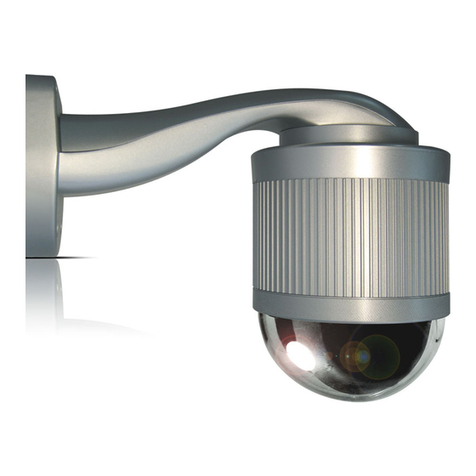
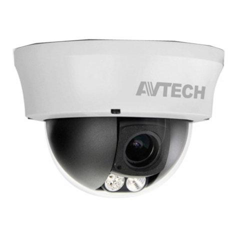
The product image shown above may differ from the actual product.
Please use this camera with a DVR which supports HD video recording.
Please read the instructions thoroughly before using the product.

IMPORTANT SAFEGUARD
C
CA
AU
UT
TI
IO
ON
N
R
RI
IS
SK
K
O
OF
F
E
EL
LE
EC
CT
TR
RI
IC
C
S
SH
HO
OC
CK
K
C
CA
AU
UT
TI
IO
ON
N:
:
To reduce the risk of electric shock, do not expose this apparatus to rain or moisture.
Only operate this apparatus from the type of power source indicated on the label.
The company shall not be liable for any damages arising out of any improper use, even if we have been advised of the possibility of
such damages.
The lightning flash with arrowhead symbol, within an equilateral triangle, is intended to alert the user to the presence
of uninsulated “dangerous voltage” within the product’s enclosure that may be of sufficient magnitude to constitute a
risk of electric shock to persons.
This exclamation point within an equilateral triangle is intended to alert the user to the presence of important
operating and maintenance (servicing) instructions in the literature accompanying the appliance.
ROHS Announcement
All lead-free products offered by the company comply with the requirements of the European law on the Restriction
of Hazardous Substances (RoHS) directive, which means our manufacture processes and products are strictly
“lead-free” and without the hazardous substances cited in the directive.
The crossed-out wheeled bin mark symbolizes that within the European Union the product must be collected
separately at the product end-of-life. This applies to your product and any peripherals marked with this symbol. Do
not dispose of these products as unsorted municipal waste.
CE Mark
This apparatus is manufactured to comply with the radio interference.
The company does not warrant that this manual will be uninterrupted or error-free. We reserve the right to revise or
remove any content in this manual at any time.

TABLE OF CONTENTS
1. OVERVIEW ................................................................................................................................................... 1
1.1 FEATURES.............................................................................................................................................. 1
1.2 PACKAGE CONTENT ............................................................................................................................. 2
1.3 DIMENSIONS.......................................................................................................................................... 2
1.4 CABLE OVERVIEW................................................................................................................................. 2
1.5 CAMERA MODE, ID &BAUD RATE SETUP ........................................................................................... 3
WHERE TO SET ................................................................................................................................... 3
SET TO IP CAMERA ............................................................................................................................. 3
SET TO TVI CAMERA........................................................................................................................... 3
SET TO AHD CAMERA......................................................................................................................... 4
2. PTZ CONTROL ........................................................................................................................................................... 5
2.1 VIA HD CCTV DVR /NVR........................................................................................................................ 5
2.2 VIA IP CAMERA INTERFACE.................................................................................................................. 6
2.3 VIA JOYSTICK AVX102 (OPTIONAL) ..................................................................................................... 8
3. CAMERA CONFIGURATIONS – TVI DVR ............................................................................................................. 9
3.1 AUTO PAN SETUP .................................................................................................................................11
3.2 CRUISE SETUP .................................................................................................................................... 12
3.3 SEQUENCE SETUP.............................................................................................................................. 13
3.4 CAMERA GUARD.................................................................................................................................. 15
3.5 HOME SETUP ....................................................................................................................................... 16
3.6 AUTO TRACKING SETUP..................................................................................................................... 17
4. CAMERA CONFIGURATIONS – IP CAMERA ........................................................................................... 18
4.1 DIGITAL PTZ (DPTZ) OPERATIONS ........................................................................................................... 18
4.2 EVENT RECORD SEARCH &PLAYBACK ...................................................................................................... 19
4.3 SYSTEM CONFIGURATION ......................................................................................................................... 20
4.3.1 Network ...................................................................................................................................... 22
4.3.2 Camera....................................................................................................................................... 29
4.3.3 VA ............................................................................................................................................... 35
4.3.4 Record........................................................................................................................................ 36
4.3.5 Storage ....................................................................................................................................... 37
4.3.6 Trigger ........................................................................................................................................ 37
4.3.7 General....................................................................................................................................... 40
SPECIFICATIONS* ....................................................................................................................................................... 45
MICRO SD CARD COMPATIBLE LIST ..................................................................................................................... 47
API ID APPLICATION FOR SMS MESSAGING ...................................................................................................... 48
PREREQUISITES FOR NETWORK SHARE............................................................................................................ 50
CHECK PC IP ADDRESS................................................................................................................................. 50
CREATE "ADMINISTRATOR"ACCOUNT.............................................................................................................. 51
SHARE FOLDER ............................................................................................................................................. 52
1
1. OVERVIEW
1.1 FEATURES
Tribrid video output of IP, TVI and AHD to fulfill different customers' requirements
Zoom lens of f4.7 ~ 94mm with 20x optical zoom and auto focus, suitable for various monitoring
environments
PTZ control for seamless monitoring:
- Capable of 360° pan rotation continuously with the tilt movement of -10° ~ 90°, allowing quick and smooth
action of the camera lens
- Auto Tracking to follow moving objects
- Hot Point support to quickly move the camera to the specified point remotely
- Up to 256 preset points & four sequence groups programmable for multiple points monitoring,
and auto pan
External alarm I/O device connection
ONVIF ( ) standard supported to simplify system integration
MicroSD card support (up to 64GB) for video storage
WDR to increase image recognizability in overexposure and dark areas
Line in / out jacks available for audio transmission
IR effective range up to 200 meters for night surveillance, and 300 meters available
in the IR Turbo mode
IP66 for outdoor application
Remote Surveillance
-- Fully compatible with iOS and Android devices, and Internet Explorer on Windows operating system
-- Push Video available on your iOS and Android devices when used with Push Video NVR series

2
1.2 PACKAGE CONTENT
Camera User manual Bracket (w/carabiner) Terminal block
1.3 DIMENSIONS
*Dimensional Tolerance: ± 5mm
1.4 CABLE OVERVIEW
Cable Description
Power cable Connect to the supplied adapter.
BNC cable Connect to an HD CCTV DVR with a coaxial cable (Used as an HD CCTV
camera).
Terminal block
1. ALARM IN Alarm input for an alarm device like magnetic contacts.
2. ALARM OUT Alarm output for an alarm device like a siren.
3. GND Ground wire
4. RS485A Used for PTZ camera or other device connection.
5. RS485B Used for PTZ camera or other device connection.
RJ45 network cable Connect to an NVR with a RJ45 network cable or directly connect to a
router (Used as an IP camera).
Line in* Colored as blue, used to connect to a microphone for audio input.
Line out* Colored as green, used to connect to a speaker for audio output.
RESET Remove the insulating coating of wire, and twist it with a ground wire
together to reset default camera
GND Ground wire
* The audio function is available only when this camera is used as an IP camera.

3
1.5 CAMERA MODE, ID & BAUD RATE SETUP
This camera could be used as an IP camera, a TVI camera and an AHD camera. Before connecting this camera to any
recorder, you may need to manually set the camera mode, ID & baudrate for the camera to work properly. Plase check
the description below for details.
WHERE TO SET
Remove the panel as indicated below to find the dip switch.
SET TO IP CAMERA
Mode:
SET TO TVI CAMERA
Mode:
You might need to set the ID and baud rate if you’re connecting to other brand’s TVI DVR:
ID: The ID number can be set from 0~255 (binary).
Please check the examples below.
Baud Rate:

4
SET TO AHD CAMERA
Mode:
You might need to set the ID and baud rate if you’re connecting to other brand’s AHD DVR:
ID: The ID number can be set from 0~255 (binary).
Please check the examples below.
Baud Rate:

5
2. PTZ CONTROL
2.1 VIA HD CCTV DVR / NVR
NOTE: The panel below is available only when the camera is used with our brand’s HD CCTV DVR or
NVR, and not all functions in the panel are supported for this camera.
Right-click to return to the live view, and click the channel with this speed dome camera connected. Then,
click on the bottom left side of the screen to show the PTZ control panel.
/ / / Up / Down / Left / Right Click the arrow keys ( / / / ) to move the
camera lens up / down / left /right.
+/ -Zoom in / out max Click to zoom in on the image to the largest / zoom out
on the image to its original size.
/ Zoom in / out Click to zoom in / out the image.
/ Focus near / far Click to adjust the focus of the image.
Auto mode
Click to activate the auto function.
Before using it, you need to assign a specific function
that will be enabled when “ ” is clicked.
For details, please see “3.1 VIA TVI DVR”.
Auto tracking Click to start auto tracking, and click again to stop.
Preset point Click to configure or go to the preset point you want to
see. For details, please see “SEQUENCE SETUP”.
Auto Focus Click to automatically adjust the focus of the camera.
Joystick
Click to enable faster and smoother pan / tilt movement
of the camera than to simply move by the arrow keys (
/ / / ).
You can also click and hold the mouse to move.
NOTE: PTZ control is also available via the optional USB joystick and EagleEyes. For details, please
check their respective user manuals.

6
2.2 VIA IP CAMERA INTERFACE
When this camera is individually used and is not connected to any NVR, PTZ control can be done via the
interface of the camera.
Step1: Open your web browser, and key in http://ipaddress:portnum in the URL address box.
For example, for the IP address 60.121.46.236 and port No. 888, please key
in ”http://60.121.46.236:888” into the URL address box, and press “Enter”.
Step2: In the login page, key in the user name and password, and enter the security code from the image
below if any. Then, click “LOGIN”.
Step3: The wizard is then started.
‧ To skip the wizard and directly access the camera live view, click “Close”.
‧ To directly access the camera live view without starting the wizard for the login next time, check
“Do not start wizard at login”.
Note: If you’re prompted to install “VLC player”, “Software” or “H264 Streaming Viewer”, please
agree to proceed the installation. Or, you might not be able to see the live view properly.
Step4: When the login is successful, the live view is shown.
Note: The buttons available depend on the camera model you have, and the user level used to log
in.

7
Function Icon Description
Config.
Switch to the system configuration page, and the functions available
for “Supervisor” and “Power User” are different.
For details, please refer to the user manual.
Arrow keys panel -- Click to move the camera lens up / up-left / down / up-right / left /
down-right / right / down-left.
Preset points -- Click the numbering of the preset point you want to move the PTZ
camera to the selected preset point.
To set preset points, please go to “Config”. For details, please refer
to the user manual.
Zoom-in / out / Click to zoom in / out the current image.
Max. Zoom-in / out / Click to zoom in the image to the largest / zoom out the image to its
original size.
Focus near / far / Click to adjust the clearness of the video images.
DPTZ Click to enable digital PTZ functions with zoom-in ratio up to 16X.
Auto Tracking
Click to activate the auto tracking function.
For setting details, please go to “Config”. For details, please refer
to the user manual.
Auto Mode
Click to activate the auto function. Before using it, you need to
assign a specific function that will be enabled when “AUTO” is
clicked.
For details, please refer to the user manual.
This function will be disabled when DPTZ is enabled.
Focus Zone
Click to assign the point for focus adjustment.
This function will be disabled when DPTZ is enabled.
Auto Move
Click to enable the auto move function. It allows the camera to
move to the direction where your cursor stays.
This function will be disabled when DPTZ is enabled.
Pan- / Tilt-Move Manually
There are three ways to manually move the camera view by:
Using the arrow key panel
Hot point – Directly click on the live view to move the camera view.
Using sliders – Click and drag sliders on the top and left side of the live view to move the camera view.
NOTE: PTZ control is also available via the optional USB joystick and EagleEyes. For details, please
check their respective user manuals.

8
2.3 VIA JOYSTICK AVX102 (OPTIONAL)
When this camera is connected to our brand’s DVR or NVR, simply plug the joystick to the recorder,
switch to the channel which connects this camera and you’re ready to control via the joystick.
When this camera is connected remotely via our free PC program, CMS Lite, simply plug this joystick to
your PC or laptop, switch to the channel which connects this camera, and you’re ready to control via the
joystick.
NOTE: CMS Lite could be downloaded from our official website and it’s only compatible with
Windows XP, Windows Vista, Windows 7 and Windows 8. For details, please check our
website.
NOTE: PTZ control is also available via the optional USB joystick and EagleEyes. For details, please
check their respective user manuals.

9
3. CAMERA CONFIGURATIONS – TVI DVR
NOTE: The method below is available only when the camera is used with our brand’s TVI DVR.
On the DVR live view, right click to show the main menu, and select ADVANCED CONFIG DCCS.
Then, select the channel which connects this camera, and click SETUP to enter the menu of camera
parameters.
ADVANCED CONFIG
C A M E R A CH1 CH2 CH3 CH4
DETECTION MENU SETUP
ALERT
NETWORK
DISPLAY
RECORD
DEVICES F.W. 1017
DCCS DEVICE AVTXXX
NOTIFY CONNECTION OK
EXIT
Item Description
BRIGHTNESS Click the current value to manually adjust the brightness of the image. The higher the
value, the brighter the image.
CONTRAST Click the current value to manually adjust the contrast of the image. The higher the
value, the higher the contrast ratio.
HUE Click the current value to manually adjust the hue of the image.
SATURATION Click the current value to manually adjust the saturation of the image. The higher the
value, the more saturated the image.
CAMERA GUARD Enable “GUARD LOCK” to temporarily disable the pan function of this camera and fix
the camera surveillance area.
For details, please refer to the section “CAMERA GUARD”.
CRUISE MODE Select the cruise mode when the is selected in the PTZ mode. There are three
options: AUTO PAN, SEQUENCE and CRUISE.
AUTO PAN: Pan within the range specified in CRUISE CONFIG.
SEQUENCE: Patrol based on the sequence group specified in CRUISE CONFIG.
CRUISE: Patrol based on the route recorded in CRUISE CONFIG.
CRUISE CONFIG The setting shown here depends on what you selected in CRUISE MODE:
AUTO PAN: Specify the range for auto pan to run.
For details, please refer to the section “AUTO PAN SETUP”.
SEQUENCE: Configure a sequence group for area patrol.
For details, please refer to the section “SEQUENCE SETUP”.
CRUISE: Customize the patrol route in 200 seconds.
For details, please refer to the section “CRUISE SETUP”.
AUTO TRACKING Set the surveillance area for auto tracking, and the tracking timeout.
For details, please refer to the section “AUTO TRACKING SETUP”.
DISPLAY ZOOM RATIO Select “ON” to show the zoom ratio on the live view.
PAN SPEED Set the speed for pan movement.
TILT SPEED Set the speed for tilt movement.
SPEED BY ZOOM Select “ON” to automatically adjust the moving speed of the camera in each zoom
ratio. In another word, the moving speed in different zoom ratio is different.
HOME Configure this camera to always return to a specific point when the camera is not
operated for the specified time.
For details, please refer to the section “HOME SETUP”.
VIDEO FORMAT Select the video format: NTSC / PAL.

10
Item Description
WHITE BALANCE Process the current image to retain color balance over a color temperature range.
The options are: AUTO, 2500K, 3200K, 4200K, 5800K & 9500K.
SHARPNESS Sharpness enhances the clarity of image detail by adjusting the aperture and
sharpening the edges in the pictures.
Hold and drag the slider to adjust the level of sharpness. The higher the value, the
sharper the image.
SLOW SHUTTER Slow shutter is used to increase the exposure time to get clearer image, for example, at
night.
The options are: AUTO, 1/15 and 1/6.
IRIS IRIS is used to adjust the amount of light reaching the image sensor for best image
results. The options are: CLOSE, AUTO (default), OPEN, OFF
MIRROR Select “ON” to rotate the images horizontally based on your installation situation when
necessary.
FLIP Select “ON” to rotate the image 180° when necessary.
3D DENOISE Click and drag the slider to adjust the level from 0 ~ 5 to decrease the noise shown in
the dark environment.
3D denoise analyzes successive pictures to decrease the noise dramatically, but the
moving objects might be shown as blurred.
2D DENOISE Click and drag the slider to adjust the level from 0 ~ 5 to decrease the noise shown in
the dark environment.
2D denoise analyzes only a single picture to decrease the noise. The moving objects
can remain smooth edges, but the effect might be limited.
EXPOSURE VALUE Drag the slider to adjust the exposure level from 0 ~ 4.
WIDE DYNAMIC RANGE Wide Dynamic Range (WDR) is used when users need to increase image
recognizability in overexposure and dark areas.
The options are: LOW / MIDDLE / HIGH / OFF
FIXED SHUTTER Shutter Speed is a function that can adjust the duration of the electronic shutter to
produce optimum image quality. Select the shutter speed suitable for your
environment.
EFLIP This function is used to keep the image upright always after pan / tilt movement.
The options are: OFF / Mechanical.
DAY AND NIGHT This function is used to configure the day and night mode:
Day: Always stay in the day mode (color).
Night: Always stay in the night mode (B/W).
Sensor: Automatically switch based on the light sensor of the camera.
Digital Input N.O. (Used with Alarm In) Normally stay in the day mode, and switch to
the night mode when the alarm is triggered.
Digital Input N.C. (Used with Alarm In) Normally stay in the night mode, and switch to
the day mode the when alarm in triggered.
DEFOG Select “ON” to enable the defog function in poor weather conditions such as fog, smog
or smoke. The captured image can be improved.
MECHANICAL IRIS CALIBRATION Select “START” to begin mechanical iris calibration.
IR CONTROL Select “AUTO” to automatically enable IR LEDs at night or in the dark environment, or
“OFF” to disable this function.
IR TURN ON LEVEL Select the level for IR light to activate. 0 ~ 20
IR DELAY TIME Configure from 1 ~ 60 seconds to delay the switch of the IR mode at night.
This is used for the environment where the light condition may change suddenly and
usually last for a short time, for example, the entrance of a parking lot. It may cause the
day & night mode switching constantly and damage the camera.
With this function, the camera will delay the mode switch at night since the light change
is temporary and unnecessary to pay attention.
RESET DEFAULT Click to reset all camera settings to their default values.
REBOOT THE SYSTEM Click to reboot the camera if necessary.

11
3.1 AUTO PAN SETUP
Step1: In the live view, right click to show the main menu.
Select ADVANCED CONFIG DCCS. Then, select the channel which connects this camera,
and click SETUP to enter the menu of camera parameters.
ADVANCED CONFIG
C A M E R A CH1 CH2 CH3 CH4
DETECTION MENU SETUP
ALERT
NETWORK
DISPLAY
RECORD
DEVICES F.W. 1016
DCCS DEVICE AVTXXX
NOTIFY CONNECTION OK
EXIT
Step2: Select CRUISE MODE, and choose AUTO PAN. Then, go to CRUISE CONFIG to select
SETUP.
Step3: You’ll see the setting panel on the bottom left side of the screen:
Icon Function Description
Left limit Move the slider to where you want to set as the most left side of the surveillance
area, and click to set.
Right limit Move the slider to where you want to set as the most right side of the
surveillance area, and click to set.
-- Tilt angle Move the slider to the height you want.
Zoom ratio Move the slider to confirm the zoom ratio you need for the current area.
-- Pan speed Set the speed to pan.
Step4: Right-click to return to the live view, and click the channel with this speed dome camera
connected. Then, click on the bottom left side of the screen to show the PTZ control panel,
and select to start.
NOTE:To stop camera panning, click again to escape.

12
3.2 CRUISE SETUP
Step1: In the live view, right click to show the main menu.
Select ADVANCED CONFIG DCCS. Then, select the channel which connects this camera,
and click SETUP to enter the menu of camera parameters.
ADVANCED CONFIG
C A M E R A CH1 CH2 CH3 CH4
DETECTION MENU SETUP
ALERT
NETWORK
DISPLAY
RECORD
DEVICES F.W. 1016
DCCS DEVICE AVTXXX
NOTIFY CONNECTION OK
EXIT
Step2: Select CRUISE MODE, and choose CRUISE. Then, go to CRUISE CONFIG to select
SETUP.
Step3: You’ll see the setting panel on the bottom right side of the screen:
a) Select the cruise group to which you want to record the route. There are 4 groups to be used.
b) Move to the scene you want the cruise to be started.
c) Click
(Record). Then, drag and hold the mouse to move the camera for route planning,
and scroll the mouse to zoom in / out. You’ll see and on the screen.
NOTE:The closer these two icons, the slower the camera moving; the farther these two icons, the
faster the camera moving.
NOTE:You have 200 seconds to customize the cruise route.
d) Click to stop route planning, and click to replay the route you just made. To discard the
route you just made, click .
Step4: Right-click to return to the live view, and click the channel with this speed dome camera
connected. Then, click on the bottom left side of the screen to show the PTZ control panel,
and select to start.
NOTE:To stop camera cruising, click again to escape.

13
3.3 SEQUENCE SETUP
Step1: On the DVR live view, click the channel with this speed dome camera connected. Then, click
on the bottom left side of the screen to show the PTZ control panel.
Step2: Click to display the preset point panel, and click to go to the setting panel.
Step3: Click / to move to the point you want to configure as a preset point, and click the
numbering you want to appoint for this point. Then, wait till you see (command sending)
appearing and disappearing on the DVR status bar.
NOTE:Up to 256 preset points could be configured.
Step4: Repeat Step3 until you’ve added all the points you need, or click to return to the Goto
panel.
Step5: In the Goto panel, select the numbering you’ve appointed for the preset points to check if they’re
working properly.
Step6: Return to the live view, and right click to show the main menu.
Select ADVANCED CONFIG DCCS. Then, select the channel which connects this camera,
and click SETUP to enter the menu of camera parameters.
ADVANCED CONFIG
C A M E R A CH1 CH2 CH3 CH4
DETECTION MENU SETUP
ALERT
NETWORK
DISPLAY
RECORD
DEVICES F.W. 1016
DCCS DEVICE AVTXXX
NOTIFY CONNECTION OK
EXIT

14
Step6: Select CRUISE MODE, and choose SEQUENCE. Then, go to CRUISE CONFIG to select
SETUP.
SEQUENCE
ACTIVE NO: 1
ACTIVE TIME (MINUTES) 3
No1 PRESET DWELL TIME PAN SPEED
No2 01 No2 600
0
255
No3 02 No4 600
0
255
No4 03 No5 600
0
255
No5 >> 04 No1 600
0
255
No6 << 05 No3 600
0
255
No7
No8
No9
No10
No11
No12
No13
No14
EXIT
ACTIVE TIME (MINUTES) Select how long the area patrolling lasts in minute.
The options are 2, 3 and 5.
DWELL TIME Select the time in second after which to move to the next point. The
time ranges from 3 to 60.
PAN SPEED Select how fast to move the camera to the next point. The speed
ranges from 0 to 255.
Step6: Select EXIT, and right click to return to the live view.
Click the channel with this speed dome camera connected. Then, click on the bottom left
side of the screen to show the PTZ control panel, and select to start.
NOTE:To stop camera panning, click again to escape.

15
3.4 CAMERA GUARD
This function is used to lock the camera to a fixed point and no pan action could be made until the lock mode
is disabled. Before using this function, make sure:
You have an iOS or android mobile device with our free app, EagleEyes, installed.
Your TVI DVR is connected to Internet, and registered in the address book of EagleEyes.
NOTE:To know how to connect the DVR to Internet, please refer to its user manual.
Step1: In the live view, and right click to show the main menu.
Select ADVANCED CONFIG DCCS. Then, select the channel which connects this camera,
and click SETUP to enter the menu of camera parameters.
ADVANCED CONFIG
C A M E R A CH1 CH2 CH3 CH4
DETECTION MENU SETUP
ALERT
NETWORK
DISPLAY
RECORD
DEVICES F.W. 1016
DCCS DEVICE AVTXXX
NOTIFY CONNECTION OK
EXIT
Step2: Select CAMERA GUARD, and enable this lock function. Then, configure the timeout after
which the camera will be fixed to the current point and any attempt to pan the camera to another
point will be failed.
CAMERA GUARD
GUARD LOCK ON
TIMEOUT (SECS) 30
Step3: Go to EagleEyes on your mobile phone or tablet, and access your TVI DVR. Then, click on the
channel with this camera connected, and choose any of the following methods to move the
camera to the point you want:

16
Step4: Return to the address book of EagleEyes, and enable Guard. The camera will fix at the point
after the time specified in Step2 unless the Guard status is disabled.
3.5 HOME SETUP
This function is used to configure this camera to always return to a specific point when the camera is not
operated for the specified time.
Step1: In the live view, and right click to show the main menu.
Select ADVANCED CONFIG DCCS. Then, select the channel which connects this camera,
and click SETUP to enter the menu of camera parameters.
Step2: Select HOME, and enable this function.
HOME
FUNCTION ON
IDLE TIME (MINUTES) 1
TYPE CRUISE
PRESET GROUP 1
PRESET NUMBER 5
IDLE TIME (MINUTES) Configure the idle time from 1 to 120 after which the camera returns to the
specified point.
TYPE Select the action to work with this function.
There are four options: PRESET / AUTO PAN / SEQUENCE / CRUISE.
PRESET GROUP
Select the preset group within which has the preset point you want to
configure. Then, go to PRESET NUMBER to select the preset point you
want.
To know how to configure preset group, please refer to the section
“SEQUENCE SETUP”.
PRESET NUMBER Select the preset point you want to force the camera returning to after the
specified time.

17
3.6 AUTO TRACKING SETUP
Step1: In the live view, right click to show the main menu.
Select ADVANCED CONFIG DCCS. Then, select the channel which connects this camera,
and click SETUP to enter the menu of camera parameters.
ADVANCED CONFIG
C A M E R A CH1 CH2 CH3 CH4
DETECTION MENU SETUP
ALERT
NETWORK
DISPLAY
RECORD
DEVICES F.W. 1016
DCCS DEVICE AVTXXX
NOTIFY CONNECTION OK
EXIT
Step2: Go to AUTO TRACKING, and select SETUP.
Step3: You’ll see the setting panel on the bottom left side of the screen:
Icon Function Description
Left limit Move the slider to where you want to set as the most left side of the surveillance
area, and click to set.
Right limit Move the slider to where you want to set as the most right side of the
surveillance area, and click to set.
-- Tilt angle Move the slider to select the tilt range of the surveillance area.
Zoom ratio Move the slider to confirm the zoom ratio you need for the current area.
-- Time Set pre-defined tracking timeout of the camera from 5 ~ 60 seconds, or drag
directly to the right end for no time limit (INFINITE).
When the locked target stops moving longer than the pre-defined tracking
timeout, the camera returns to the point it originally monitors after the preset
tracking timeout.
Step4: Right-click to return to the live view, and click the channel with this speed dome camera
connected. Then, click on the bottom left side of the screen to show the PTZ control panel,
and select to start.
NOTE:To stop camera panning, click again to escape.
Table of contents
Other Avtech Security Camera manuals

Avtech
Avtech DG104 Operating instructions

Avtech
Avtech AVM359 User manual

Avtech
Avtech AVC508 User manual

Avtech
Avtech AVN222 User manual

Avtech
Avtech Ezum DGC1304-10 User manual

Avtech
Avtech AVM457A User manual

Avtech
Avtech DGC5445ASE Series User manual

Avtech
Avtech AVM3445-LW User manual

Avtech
Avtech AVM328A Manual

Avtech
Avtech AVN420 User manual

Avtech
Avtech AVN363 User manual

Avtech
Avtech AVM503 User manual

Avtech
Avtech AVM2200T User manual

Avtech
Avtech IC-YGN2003 User manual

Avtech
Avtech DGC5105T User manual

Avtech
Avtech AVT1104 User manual

Avtech
Avtech AVC489A User manual

Avtech
Avtech DG108X User manual

Avtech
Avtech MEGAPIXEL WIRELESS NETWORK CAMERA SERIES User manual

Avtech
Avtech AVM359a User manual