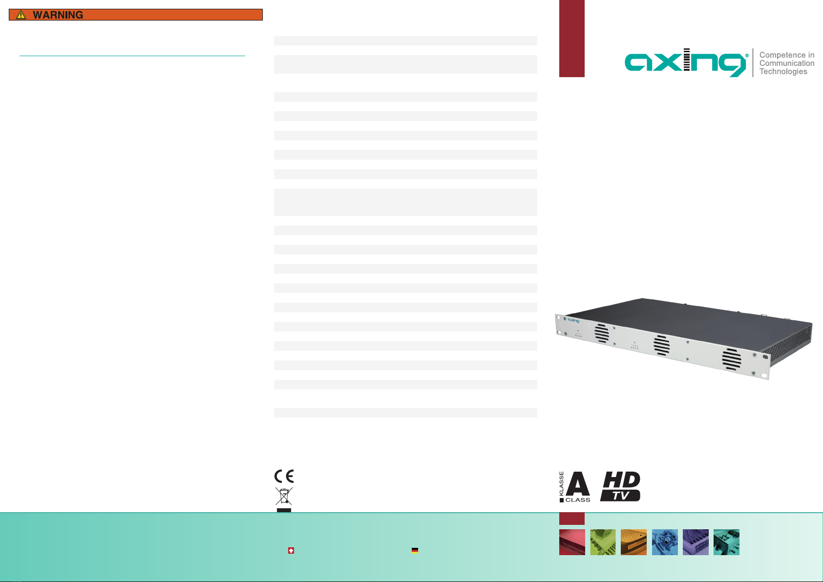
axing MIE 3-02 User manual

QA_MIE-3-6-02.pdf | 2021-04-14
Beachten Sie die dem Gerät beiliegenden Sicherheitshinweise!
Diese sind auch unter der folgenden Internetadresse abrufbar:
https://download.axing.com/BAs/Sicherheitshinweise_9sprachig.pdf
Benutzen Sie das Gerät ausschließlich wie in dieser Betriebsanleitung
beschrieben und insbesondere nach dem Stand der Technik.
Wird das Gerät für andere Einsätze verwendet, wird keine Gewährleis-
tung übernommen!
Technische Verbesserungen, Änderungen im Design, Druckfehler und Irrtümer
vorbehalten.
Hersteller
AXING AG
Gewerbehaus Moskau
8262 Ramsen
EWR-Kontaktadresse
Bechler GmbH
Am Rebberg 44
78239 Rielasingen
CHP - Compact High Performance Kopfstellen
MIE 3-02 | MIE 6-02
MIE 3-02/48 | MIE 6-02/48
premium-line
IP zu DVB-T2
8Kext | 49,8 Mbps
Quickstart-Anleitung
Technische Daten:
Hinweis: Sie finden die vollständigen technischen Daten indem Sie auf www.axing.com
im Suchfeld den Artikel eingeben.
Hiermit erklärt die AXING AG, dass die gekennzeichneten Produkte den
geltetenden Richtlinien entsprechen.
WEEE Nr. DE26869279 | Elektrische und elektronische Komponenten nicht
mit dem Restmüll, sondern separat entsorgen.
Typ MIE 3-02 MIE 6-02
IPTV-Eingang
Unterstützte Transport-
streams SPTS, MPTS (CBR/VBR)
Max. Anzahl
(ausMPTSoderSPTS) 512 2×512
Unterstützte Protokolle IP V4; UDP; RTP; IGMP v2, v3
Gesamtnettodatenrate 1 × 900 Mbps 2 × 900 Mbps
Ausgang
Anzahl Kanäle 1 × 3 × DVB-T2 2 × 3 × DVB-T2
Frequenzbereich 109…862 MHz
Kanalbandbreite 7 MHz, 8 MHz
Mögliche Frequenzänderung -4…+4 MHz (0.5 MHz steps)
Anschluss 1 × F-Buchse 2 × F-Buchse
Messbuchse 1 × F-Buchse (–30 dB) 2 × F-Buchse (–30 dB)
Ausgangsmodulation
Konformität
EN 50083-9 | ETSI TS 101 154 | ETSI EN300 429 |
ETSIEN300 744
DVB-T2 acc. to EN 302 755, mode A (single PLP)
Typ QPSK, QAM16, QAM64, QAM256
Unterstützte Ausgangsformate MPEG-2/H.262, MPEG-4/H.264 and HEVC/H.265
MER ≥ 43 dB
BER ≥9x10⁻⁹
Schulterdämpfung ≥ 56 dB
C/N ≥45 dB
Reflexion >14 dB
Bitrate, max. 49,8 Mbps
FFT 1K, 2K, 4K, 8K, 8Kext mode
FEC 1/2, 3/5, 2/3, 3/4, 4/5, 5/6
Schutzintervall 1/4, 19/128, 1/8, 19/256, 1/16, 1/32, 1/128
Schnittstellen
IPTV-Eingang 1 x RJ45 2 x RJ45
CAS/IPTV (redundant) 1 x RJ45 2 x RJ45
Konformität IEEE 802.3, 1000 Base-T (GigE)
Konfiguration/CAS 1 × RJ-45 2 × RJ-45
Konformität IEEE 802.3, 10/100 Base-T
Allgemein
Betriebsspannung 100…240 VAC/50…60 Hz
48 VDC
Leistungsaufnahme 30 W 60 W
Betriebstemperaturbereich
(gemäßEN60065) –10°C…+50°C

Produktbeschreibung
Die Kopfstellen wandeln IPTV-Transportstreams (SPTS und MPTS) in
DVB-T2-Ausgangskanäle.
MIE 6-02
Ethernet-Switch
Potentialausgleich
Coax
Konfiguration
IPTV
MIE 3-02 Beinhaltet 1 Modul, unterstützt SPTS und MPTS (auch gemischt),
wandelt maximal 512 Eingangs-Streams in 3 x DVB-T2
Ausgangskanäle.
MIE 6-02 Beinhaltet 2 Module, unterstützt SPTS und MPTS (auch gemischt),
wandelt maximal 2×512 Eingangs-Streams in 2 x 3 DVB-T2-
Ausgangskanäle.
Lieferumfang
1 × IP to DVB-T2
2 × Netzkabel
1 × Quickstartanleitung (Sie finden die vollständige Betriebsanleitung zum
Download indem Sie auf www.axing.com im Suchfeld den Artikel einge-
ben)
Verfügbares Zubehör
MIM 3-02 Erweiterungsmodul für MIE 3-02 oder MIE 3-02/48, zur Erweite-
rung auf 2 × 512 Eingangs-Streams und 2 × 4 DVB-T2-Ausgangs-
kanäle.
MIS 1-11 Softwareerweiterung für MIE-Geräteredundanz
Bietet die Möglichkeit, ein Gerät (z.B. bei Ausfall) durch ein Ba-
ckup-Gerät zu ersetzen.
MKS 1-02 Softwareerweiterung für CASimulcrypt
Bietet die Möglichkeit Programme zu verschlüsseln.
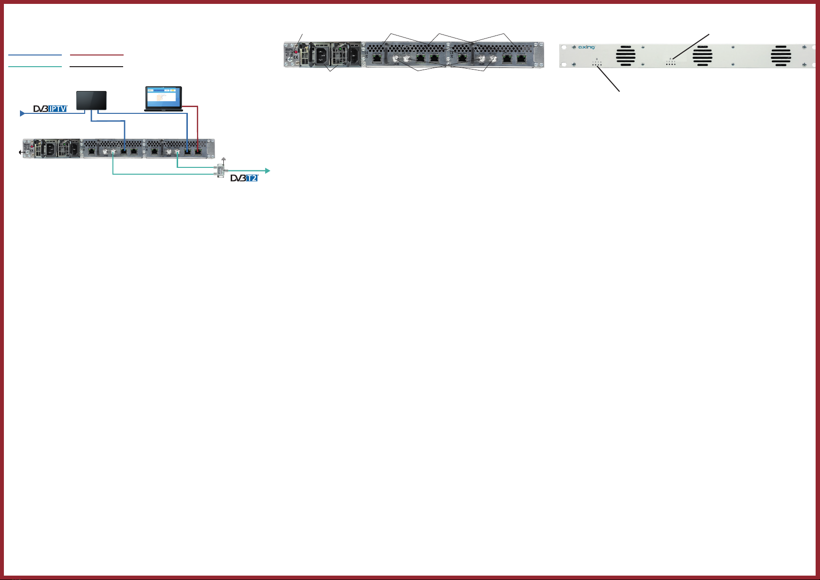
Anzeigeelemente
LEDs 1…3
des Moduls B (MIE 6-02)
LEDs 1…3
des Moduls A (MIE 3-02/6-02)
Die LEDs zeigen den Zustand der Ausgangsmodulatoren an:
9Wenn ein Modulator mit Programmen befüllt ist und der Modulator nicht
überlastet ist, leuchtet die entsprechende LED grün.
9Wenn ein Modulator eingeschaltet, aber nicht befüllt ist (ohne Inhalt),
blinkt die entsprechende LED.
9Wenn ein Modulator überlastet ist (zu viel Inhalt), leuchtet die LED rot
9Wenn ein Modulator ausgeschaltet ist, ist die entsprechende LED aus.
Konfiguration
Die Konfiguration der Geräte erfolgt über eine grafische Benutzeroberfläche.
Für den Zugriff auf die Benutzeroberfläche benötigen sie einen handelsübli-
chen PC/Laptop inklusive Netzwerkschnittstelle, handelsüblichem Netzwerk-
kabel und die aktuelle Version eines Webbrowsers.
Das MIE 3-02 enthält ein Modul A
Werks-IP-Adresse des Moduls A: 192.168.0.145
Subnetz-Maske: 255.255.255.0
Das MIE 6-02 enthält zwei Module A und B. Jedes Modul hat eine eigene
Konfigurationsschnittstelle und eine eigene IP-Adresse.
Werks-IP-Adresse des Moduls A: 192.168.0.145
Werks-IP-Adresse des Moduls B: 192.168.0.148
Subnetz-Maske: 255.255.255.0
Zugriff auf die Konfigurationsoberfläche:
Ändern Sie die IP-Adresse Ihres PC/Laptop z.B. auf 192.168.0.1, Sub-
netz-Maske 255.255.255.0.
Schließen Sie den PC am RJ-45-Ethernet-Anschluss Control an
Geben Sie jetzt die IP-Adresse des Moduls in den Web Browser ein.
Die Konfigurationsoberfläche ist mit einem Kennwort geschützt.
Geben Sie das werkseitig eingestellte Passwort Ramsen8262 ein (ändern
Sie das Passwort nach der ersten Inbetriebnahme).
Klicken Sie auf die Schaltfläche ENTER PASSWORD.
Die Startseite öffnet sich.
Folgen Sie den Schritten der Phase 1, 2 und 3, um das Gerät zu konfigu-
rieren.
Anschlüsse
Messbuchsen HF-Ausgänge
IPTV-Eingänge
CAS-Schnittstellen*
Konfigurations-Schnittstellen
CAS-Schnittstellen*
2 × redundante Netzteile
Redundante IPTV-Eingänge
CAS-Schnittstellen*
Potentialausgleichsanschluss
* Die Anschlüsse CAS/IN2, IPTV IN1 und Control können als Schnittstelle für den CAS-Server konfiguriert werden.
Montage und Anschluss
Vor Montage und Anschluss Netzstecker ziehen!
Montage im 19“-Rack
Es muss mindestens 5 cm Freiraum vor und hinter dem Gerät gegeben sein.
Schieben Sie das Gerät in das 19“ Rack.
Schrauben Sie das Gerät mit vier Schrauben fest.
Potentialausgleich
Gerät gemäß EN 60728-11 am Potentialausgleich anschließen.
Verwenden Sie den Potentialausgleichsanschluss am Gerät.
Um den Außenleiter der Koaxialkabel am Potentialausgleich anzuschließen,
verwenden Sie z. B. QEW Erdungswinkel oder CFA 7-01 Erdungsblöcke.
Spannungsversorgung 100…240VAC
Schließen Sie beide Netzteile mit den beiliegenden Kabeln an
100…240VAC an.
Spannungsversorgung 36…60 VDCC
Die Anschlüsse für die Spannungsversorgung bestehen aus 2 × M4-Schrau-
ben.
Verbinden Sie die DC-Anschlüsse mit 36… 60 VDC.
Wichtig: Achten Sie auf die richtige Polung. Verwenden Sie ausreichende
Leiterquerschnitte.
IPTV-Eingang
Schließen Sie den IPTV-Eingang an einem Ethernet-Switch an, der mit der
IPTV-Quelle verbunden ist. Verwenden Sie dazu Class 5/6 Ethernet-Kabel mit
RJ-45-Steckern.
HF-Ausgang
Verbinden Sie den Ausgang (RF OUT) mit dem vorhandenen Verteilnetz.
Verwenden Sie hierfür ein hochgeschirmtes Koaxialkabel mit einem F
Anschlussstecker.
Upgrade des MIE 3-02:
Das MIE 3-02 kann um ein Modul MIM 3-02 erweitert werden.
Trennen Sie das Gerät vom Stromnetz.
Demontieren Sie die Abdeckplatte auf der Rückseite.
Setzen Sie das Modul vorsichtig ein. Das Modul rastet spürbar in die Kon-
takte ein.
Schrauben Sie das Modul mit den Schrauben der Abdeckplatte fest.
Schließen Sie dann das Gerät wieder an.
Konfigurieren Sie das neue Modul so, wie das Modul B im MIE 6-02.

QA_MIE-3-6-02.pdf | 2021-04-14
Observe the safety instructions supplied with the device!
They are also available at the following Internet address:
https://download.axing.com/BAs/Sicherheitshinweise_9sprachig.pdf
Use the device only as described in these operating instructions and in
particular in accordance with the state of the art.
If the device is used for other purposes, no warranty will be assumed!
Technical improvements, changes in design, printing- and other errors reserved.
Manufacturer
AXING AG
Gewerbehaus Moskau
8262 Ramsen
EEA contact address
Bechler GmbH
Am Rebberg 44
78239 Rielasingen
CHP - Compact High Performance Headends
MIE 3-02 | MIE 6-02
MIE 3-02/48 | MIE 6-02/48
premium-line
IP to DVB-T2
8Kext | 49.8 Mbps
Quick start guide
Technical data:
Herewith AXING AG declares that the marked products comply with the valid
guidelines.
WEEE Nr. DE26869279 | Electrical and electronic components must not be
disposed of as residual waste, it must be disposed of separately.
Note: You find the detailed technical data by entering the article in the search field at
www.axing.com.
Type MIE 3-02 MIE 6-02
IPTV input
Supported input transport
streams SPTS, MPTS (CBR/VBR)
Max. number
(outofSPTSorMPTS) 512 2×512
Supported protocols IP V4; UDP; RTP; IGMP v2, v3
Total net data rate 1 × 900 Mbps 2 × 900 Mbps
Output
Number of channels 1 × 3 × DVB-T2 2 × 3 × DVB-T2
Frequency range 109…862 MHz
Channel bandwidth 7 MHz, 8 MHz
Possible frequency shift -4…+4 MHz (0.5 MHz steps)
Connector 1 × F-female 2 × F-female
Output level adjustable 85…105 dBµV
Output modulation
Compilance
EN 50083-9 | ETSI TS 101 154 | ETSI EN300 429 |
ETSIEN300 744
DVB-T2 acc. to EN 302 755, mode A (single PLP)
Type QPSK, QAM16, QAM64, QAM256
Supported output formats MPEG-2/H.262, MPEG-4/H.264 and HEVC/H.265
MER ≥ 43 dB
BER ≥9x10⁻⁹
Shoulder attenuation ≥ 56 dB
C/N ≥45 dB
Reflection >14 dB
Bit rate, max 49.8 Mbps
FFT 1K, 2K, 4K, 8K, 8Kext mode
FEC 1/2, 3/5, 2/3, 3/4, 4/5, 5/6
Guard interval 1/4, 19/128, 1/8, 19/256, 1/16, 1/32, 1/128
Interfaces
IPTV intput 1 x RJ45 2 x RJ45
CAS/IPTV (redundant) 1 x RJ45 2 x RJ45
Compilance IEEE 802.3, 1000 Base-T (GigE)
Configuration/CAS 1 × RJ-45 2 × RJ-45
Compilance IEEE 802.3, 10/100 Base-T
General
Operation voltage 100…240 VAC/50…60 Hz
48 VDC
Power consumption 30 W 60 W
Operating temperature range
(acc.toEN60065) –10°C…+50°C

Product description:
The headends convert IPTV transport streams (SPTS and MPTS) into DVB-T2
output channels.
MIE 6-02
Equipotential bonding
Ethernet switch
Coax
Configuration
IPTV
MIE 3-02 Includes 1 module, supports SPTS and MPTS (also mixed),
transmodulates max. 512 input streams in 3 DVB-T2 output
channels.
MIE 6-02 Includes 2 modules, supports SPTS and MPTS (also mixed),
converts a maximum of 2 × 512 input streams into 2 x 3 DVB-T2
output channels.
Scope of delivery:
1 × IP to DVB-T2
2 × AC power cord (MIE 8-00, MIE 16-00 and MIE 32-00 only)
1 × Quick start guide (You can call up the detailed operation instructions for
download by entering the article in the search field at www.axing.com)
Available Accessories
MIM 3-02 Extension module for MIE 3-02 or MIE 3-02/48 for extension to
2× 512 input streams and 2 x 4 DVB-T2 output channels.
MIS 1-11 Software extension for MIE device redundancy
Offers the possibility to replace a device with another device, e.g.
in case of failure.
MKS 1-02 Software extension for CASimulcrypt
Offers the possibility to encrypt programmes.
Display elements
LEDs 1…3
of modul B (MIE 6-02)
LEDs 1…3
of module A (MIE 3-02/6-02)
The LEDs show the state of the output modulators:
9When a modulator is filled with content and the modulator is not over-
loaded, the corresponding LED lights up green.
9If a modulator is on but not filled (without content), the corresponding
LED flashs.
9If a modulator is overloaded (too much content), the LED lights up red.
9In case a modulator is turned off, the corresponding LED is off.
Configuration:
The device is configured via the graphical user interface.To access the
user interface, you need a standard PC/laptop with a network interface, a
commercially available network cable and the actual version of the installed
web browser.
The MIE 3-02 includes one module A
Default IP address of module A: 192.168.0.145
Subnet mask: 255.255.255.0
The MIE 6-02 includes two modules A and B. Each module has its own
configuration interface and its own IP address.
Default IP address of module A: 192.168.0.145
Default IP address of module B: 192.168.0.148
Subnet mask: 255.255.255.0
Accessing the configuration interface:
Change the IP address of your PC/laptop, e.g. to 192.168.0.11, subnet
mask: 255.255.255.0
Connect the PC to the RJ-45 Ethernet connector Control.
Enter the IP address of the connected module in the web browser.
The configuration screen is password-protected:
Enter the default password Ramsen8262 (after the first log-in, the
password should be changed).
Click the „Enter password“ button.
This will open the start page.
Follow the steps of phase 1, 2 and 3 to configure the device.
Connectors
Test ports RF outputs
IPTV inputs
CAS interfaces*
Configuration interfaces
CAS interfaces*
2 × redundant power supply units
Redundant IPTV inputs
CAS interfaces*
Equipotential bonding connection
* The ports CAS/IN2, IPTV IN1 and Control can be configured as the interface for the CAS server.
Mounting and Installation:
Before mounting and installation, pull the mains plug!
Mounting in a 19“ rack
For 19-inch rack mounting, there must be at least 5 cm clearance in front of
and behind the unit.
Slide the device into the 19 „rack.
Fix the device with four screws.
Equipotential bonding
The device must be connected to the equipotential bonding according to EN
60728-11.
Use the equipotential bonding connection at the device.
To connect the outer conductor of the coaxial cable to the equipotential
bonding, use e.g. QEW earthing angles or CFA earth connection blocks.
Power supply 100…240 VAC
Connect both power supplies with the enclosed cables to 100…240VAC.
Power supply 36…60 VDC
The power supply input connectors are 2 × M4 screws
Connect the DC connectors to 36…60 VDC.
Important: Ensure that the polarity is correct. Use sufficient conductor cross
sections.
IPTV input
Connect the IPTV input to an Ethernet switch connected to the IPTV source.
Use Class 5/6 Ethernet cables with RJ-45 connectors.
RF output
Connect the output (RF OUT) of the device to the established distribution
network. Use a high-shielded coaxial cable with an F connector.
Upgrading a MIE 3-02:
The MIE 3-02 can be extended by a further module MIM 3-02.
Disconnect the device from the mains.
Disassemble the cover plate on the back.
Insert the module carefully.
The module noticeably snaps into the contacts.
Screw the module with the screws of the cover plate.
Then reconnect the device.
Configure the new module in the same way as module B in the MIE6-02.
Other manuals for MIE 3-02
1
This manual suits for next models
3
Table of contents
Languages:
Other axing Media Converter manuals

axing
axing HoE 1-00 User manual

axing
axing RF DTM-8HD/C-19S User manual

axing
axing premium-line SVE 5502-09 User manual

axing
axing Basic-line AVC 1-00 User manual

axing
axing Premium EOC 30-01 User manual

axing
axing SAB 5501-10 User manual

axing
axing HKI 41-34 User manual

axing
axing HKI-135 User manual

axing
axing HKC 1-00 User manual

axing
axing HKI 81-34 User manual