4
INTRODUCTION
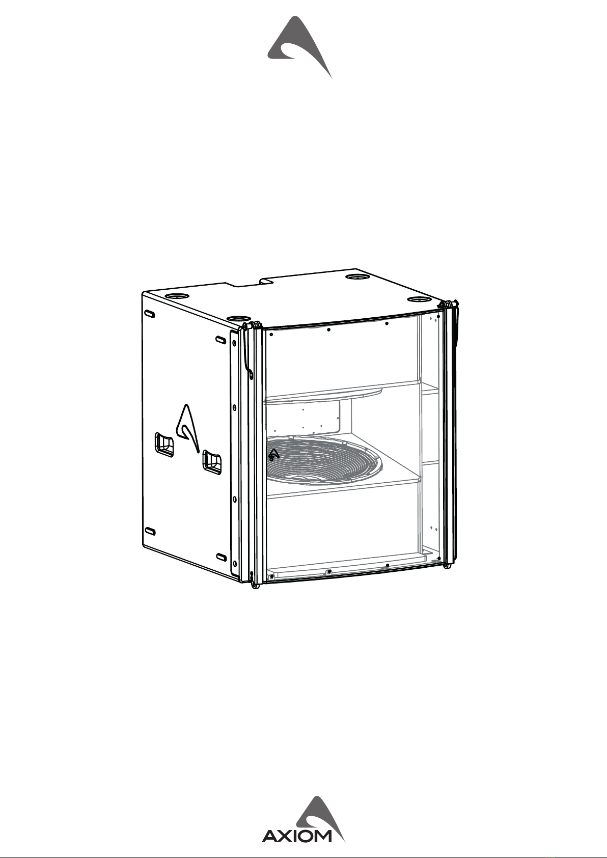
The SW36XFAV2 subwoofer is designed to deliver high quality low frequency reproducon where very high output is a key
requirement, together with well dened deep bass response and fast transient response. Its compact size and light weight make it
suitable for several dierent uses, ranging from touring applicaons to xed installaons and high-level dance clubs.
The SW36XFAV2 is a very high quality powered subwoofer system featuring some of the most advanced technologies for low
frequency reproducon. Its unique and innovave design is based on a conguraon that can be dened as Manifolded Band Pass.
It uses manifolding of the front side of the cones to maximize the mutual coupling between the two drivers. This innovave
conguraon does not use any large resonant cavity to load the speaker, but very compact cavies in order to obtain advantages
in terms of denion, both at the lowest end and the upper bass.
The SW36XFAV2 subwoofer system is equipped with two high power 18” (460mm) transducers capable of very long excursion (up to
30mm peak-to-peak), and featuring a a large displacement suspension system. These transducers use Tetracoil technology, where
two dierent, axially separated magnec gaps and two inside-outside 100mm (4” ) diameter voice coils are wound on the same
former and suspended evenly in the two magnec gaps. This creates an equivalent voice coil diameter greater than 6”, resulng
in a larger heat dissipaon area for and increased power handling. Addional key advantages of the Tetracoil technology are also
minimized distoron and a very symmetric and at inductance curve. Cones are made of very high-sness berglass reinforced
paper, featuring also invisible water repellent treatment. The SW36XFAV2 is processed by 40bit oang point CORE2 DSP and is
powered by a high eciency CLASS D amplier module with a newly designed power supply equipped with PFC, which reduces the
power consumpon while enhancing reliability and consistency in all operang condions. The innovave technology used for these
ampliers oers performance at the top of the range, such as superior sound denion at any audio frequency, very high dynamics
for low level signals, and very low distoron even at maximum power.
TECHNICAL SPECIFICATION
SYSTEM Amplier Type Class D amplier with SMPS & PFC
System’s Acousc Principle Manifolded Band Pass Output Power 2000 W + 2000 W
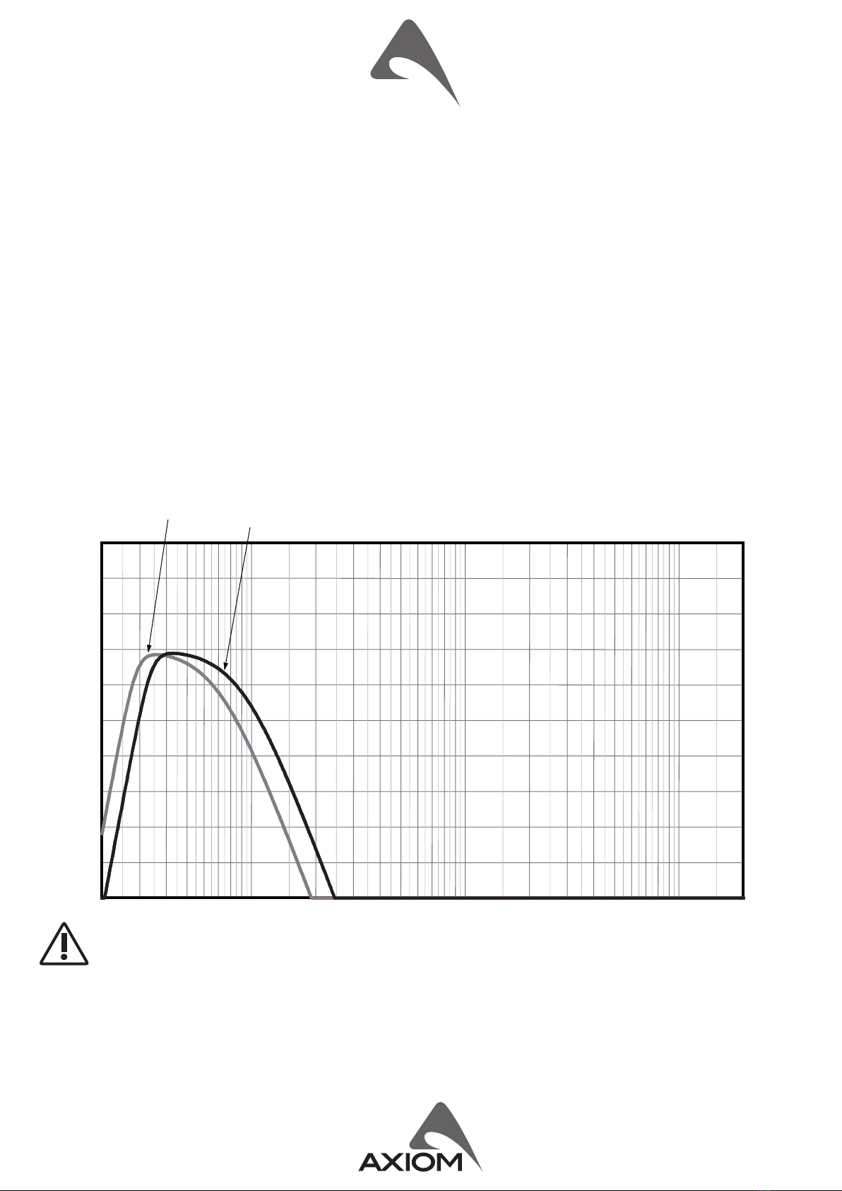
Frequency response (±3 dB) 36 Hz – 100 Hz (Processed) Mains Voltage Range (Vac) 100 - 240 V~ ±10% 50/60 Hz
Maximum Peak SPL @ 1m 143 dB Consumpon* 600 W (nominal) 2000 W (max)
TRANSDUCERS IN / OUT Connectors Neutrik XLR-M / XLR-F
Type Two 18” (460 mm), 4” (100 mm) VC 8Ω IN / OUT Network Connectors ETHERCON® (NE8FAV)
Cone Water repellent, epoxy coated plates Mains Connector PowerCon® (NAC3MPXXA)
Voice Coil Type
100mm (4in) Tetracoil dual voice coil,
equivalent to a single coil diameter
larger than 152mm (>6in)
Mains Link Connector PowerCon® (NAC3MPXXB)
Cooling Variable speed DC fan
ENCLOSURE & CONSTRUCTION
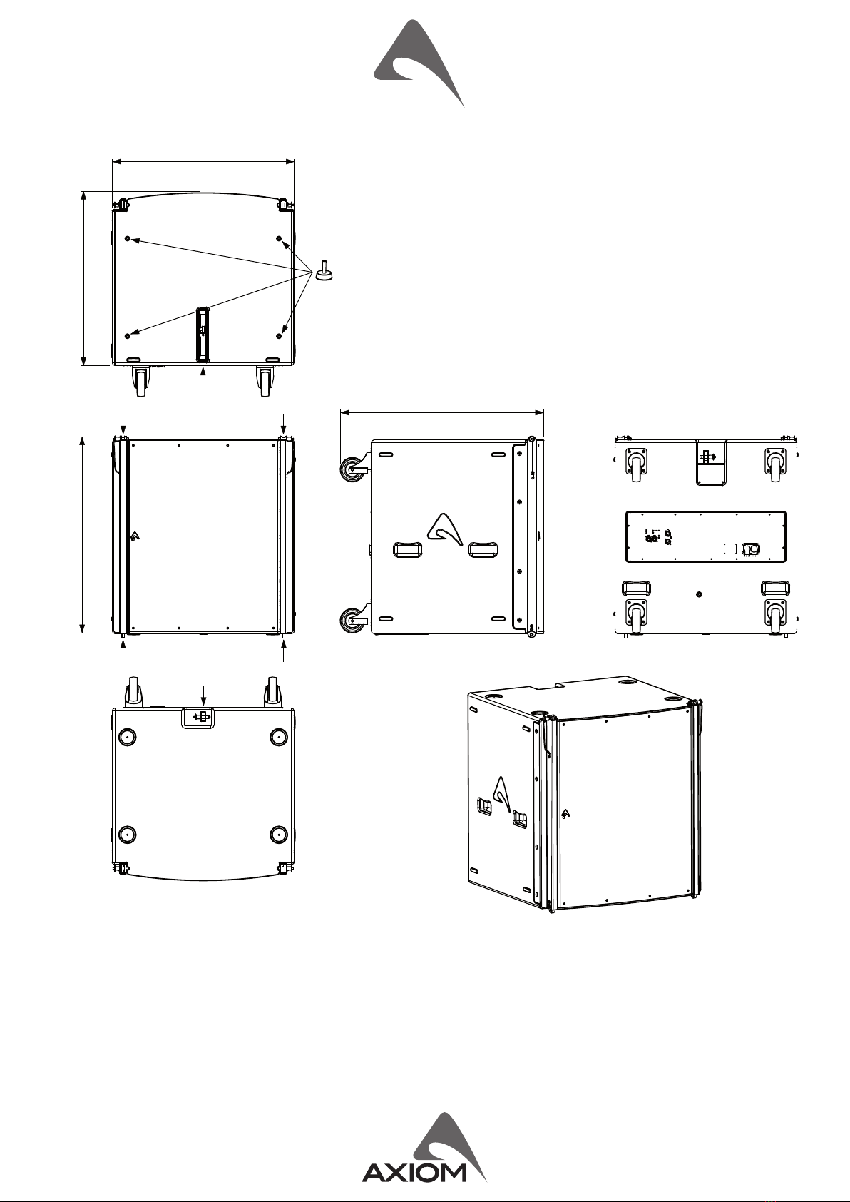
Suspension Ultra linear suspension behavior Width 746 mm (29.4”)
ELECTRICAL Height 795 mm (31.3”)
Input Impedance 20 kΩ balanced Depth 710 mm (27.9”)
Input Sensivity +4 dBu / 1.25 V Depth Including Wheels 838 mm (32.9”)
Signal Processing
CORE2 processing, 40bit oang
point SHARC DSP, 24 bit AD/DA
converters
Enclosure material 15 mm, reinforced Phenolic Birch
Paint High resistance, water based paint
Wheels 4 heavy-load 100 mm ø (oponal)
Direct access Controls 4 Presets: Standard, InfraSub, Cardioid,
User. Network Terminaon, GND Link
Transport 6 handles
Side Suspension High Strength Steel with ¼ Fast Pin
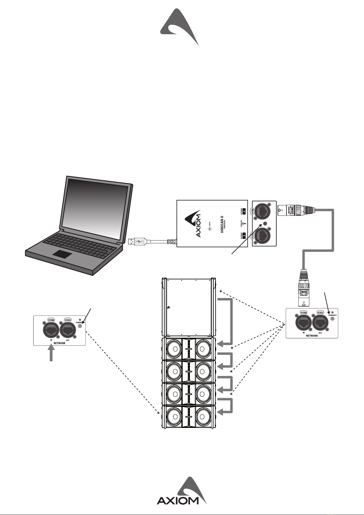
Remote Controls PRONET AX control soware Back Suspension High Strength Steel with ¼ Fast Pin
Network protocol CANBUS Net Weight 91.2 Kg (201.1 lbs.) without wheels
* Nominal consumpon is measured with pink noise with a crest factor of 12 dB, this can be considered a standard music program.
INDEX
INTRODUCTION ...........................4
TECHNICAL SPECIFICATION ..................4
MECHANICAL DRAWING ....................5
OPTIONAL ACCESSORIES ....................5
SPARE PARTS ..............................6
I/O AND CONTROL OPERATIONS ..............6
MAINS~ IN. . . . . . . . . . . . . . . . . . . . . . . . . . . . . . . . 6
MAINS~ OUT ..............................6
ON ......................................6
PROT ....................................6
SIGN LIMIT ...............................6
INPUT ...................................6
LINK .....................................6
GND LIFT .................................6
NETWORK IN/OUT .........................6
TERMINATE ...............................6
PRESET BUTTON ...........................7
PRONET AX ...............................8
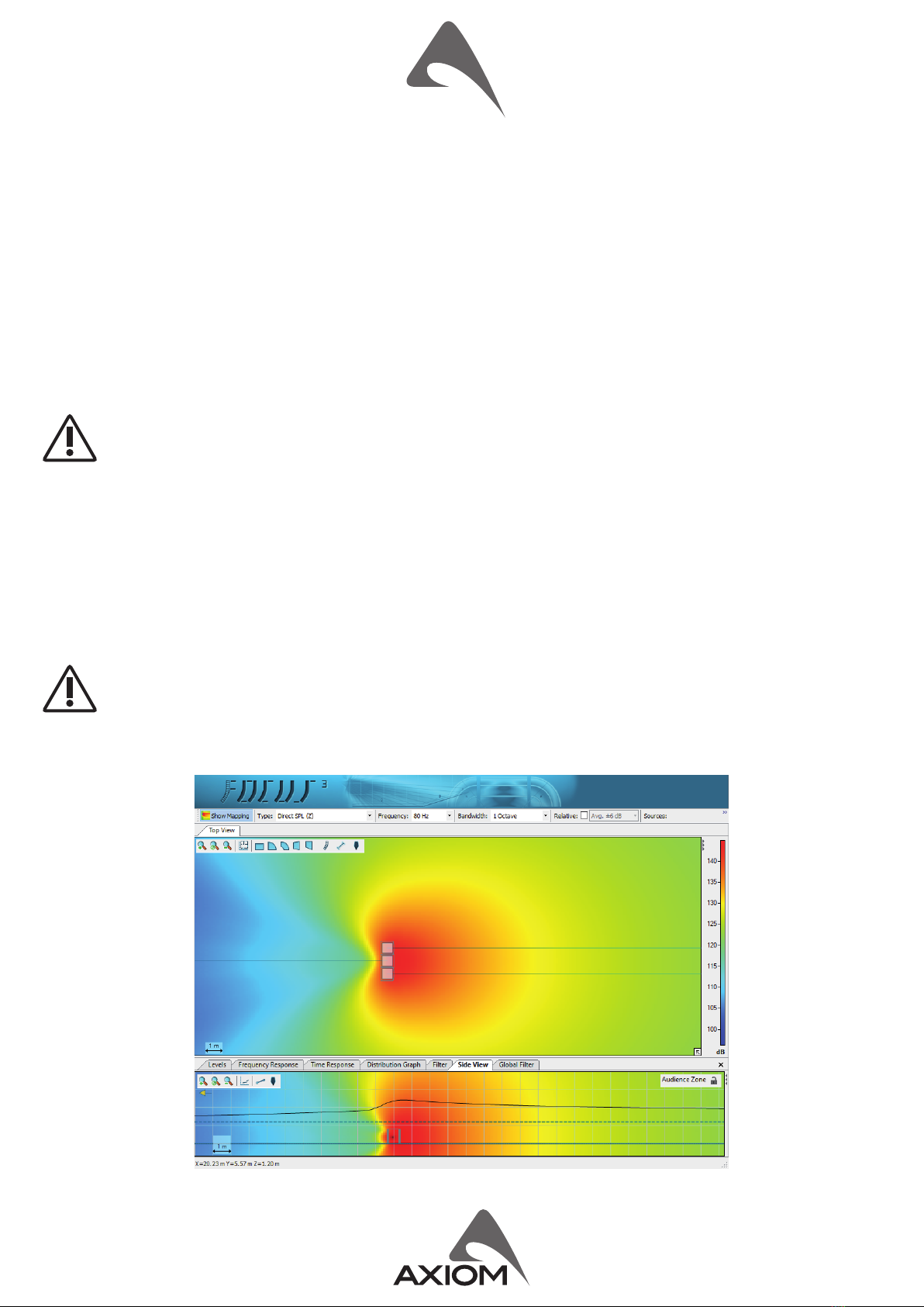
PREDICTION SOFTWARE: EASE FOCUS 3 ........9
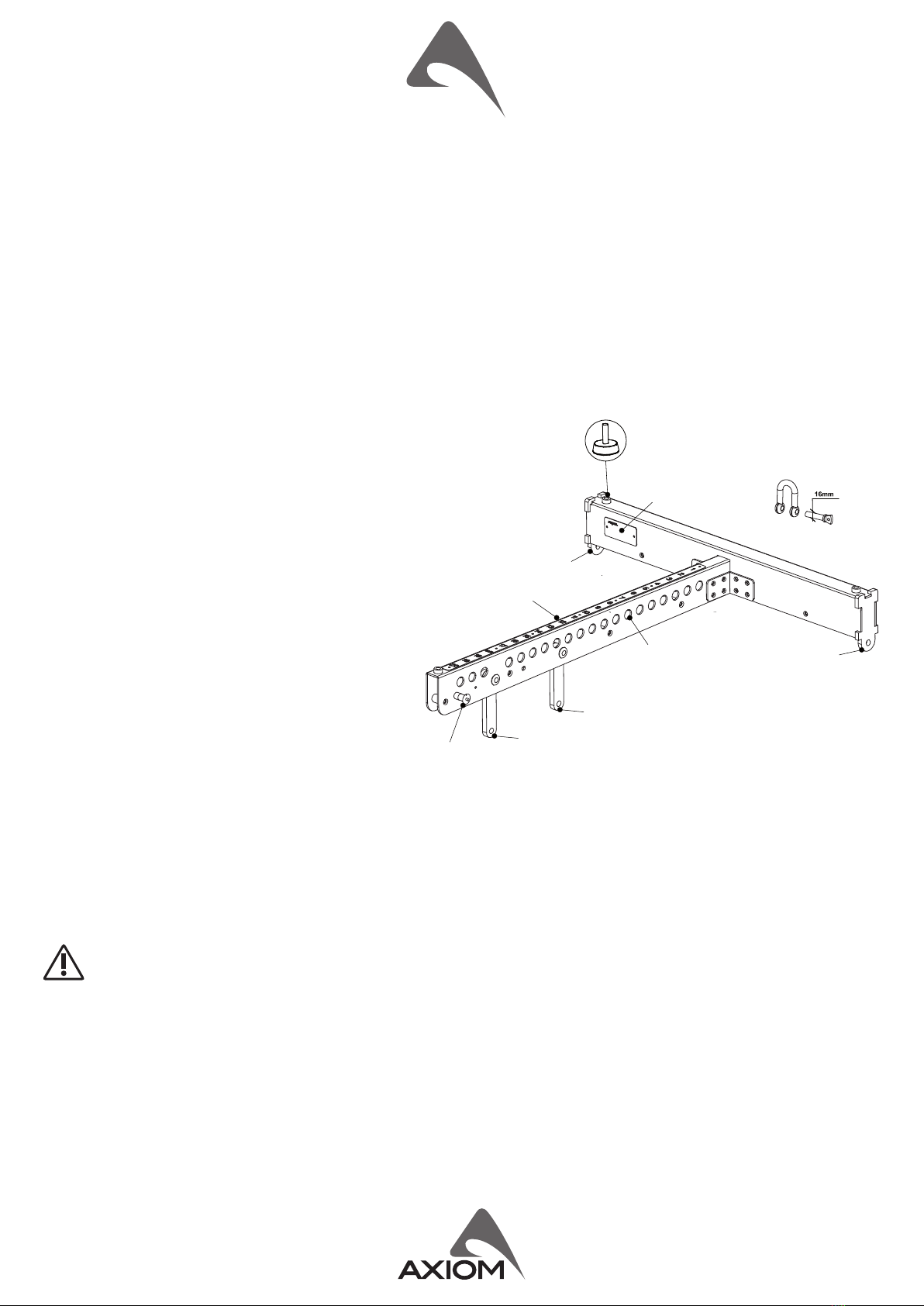
AIMING and SUSPENDING
INSTRUCTIONS (FLOWN SET UP) .............10
CARDIOID SET UP .........................14