AXIOMATIC Tri-Axial J1939 CAN User manual

User Manual UMAX0608XX-1000
Version 9B
Firmware 9.xx,
EA 5.15.108.0+
USER MANUAL
Tri-Axial J1939 CAN Inclinometer
P/N: AX060800, AX060830 – Two M12 Connectors, Both CAN
P/N: AX061000 – Two M12 Connectors, CAN, 3 Analog Outputs
P/N: AX060808, AX060838 – Vertical Mount, Two M12 Connectors, Both CAN
P/N: AX060806, AX060810 – One DT15-4P Connector
P/N: AX060807, AX060811 – One DT15-4P Connector, CAN Termination
In Europe:
Axiomatic Technologies Oy
Höytämöntie 6
33880 Lempäälä - Finland
Tel. +358 103 375 750
Fax. +358 3 3595 660
www.axiomatic.fi
In North America:
Axiomatic Technologies Corporation
5915 Wallace Street
Mississauga, ON Canada L4Z 1Z8
Tel. 1 905 602 9270
Fax. 1 905 602 9279
www.axiomatic.com

UMAX0608XX‐1000.Tri‐AxialJ1939CANInclinometer.Version9B ii
ACRONYMS
3D Three-Dimensional
CAN Controller Area Network
CE The CE mark, or formerly EC mark, is a mandatory conformity
marking for certain products sold within the European Economic Area
(
EEA
)
since 1985
DM Diagnostic message. Defined in J1939/73 standard
EA Electronic Assistant®. PC application software from Axiomatic,
primarily designed to view and program Axiomatic control
configuration parameters (setpoints) through CAN bus using J1939
Memor
y
Access Protocol
ECU Electronic control unit
EMC Electroma
g
netic compatibilit
y
EMI Electroma
g
netic Interference
G Gravitational Acceleration on Earth
GPS Global Positioning System
Grms Root Mean Square Acceleration in G units
Hz Hertz
IEC International Electrotechnical Commission
LSB Less Significant Byte
MEMS Microelectromechanical system
NED North-East-Down coordinate system
PC Personal Computer
PGN Parameter Group Number. Defined in J1939/73 standard
P/N Part Number
RoHS Restriction of Hazardous Substances
SAE J1939 CAN-based higher-level protocol designed and supported by the
Societ
y
of
A
utomobile En
g
ineers
(
SAE
)
SAE J670 Vehicle Dynamics Terminology standard designed and supported by
the Societ
y
of
A
utomobile En
g
ineers
(
SAE
)
SSI Slope Sensor Information (PGN 61459)
SSI2 Slope Sensor Information 2 (PGN 61481)
UM User Manual
USB Universal Serial Bus
VDS Voltage Direct Current or Vehicle Direction/Speed (PGN 65256)
VDS2 Vehicle Direction/Speed 2 (PGN 64905)
XOR Exclusive or, a logical operation

UMAX0608XX‐1000.Tri‐AxialJ1939CANInclinometer.Version9B iii
TABLE OF CONTENTS
1INTRODUCTION ................................................................................................................. 5
2INCLINOMETER DESCRIPTION ........................................................................................ 6
2.1Theory of Operation ..................................................................................................... 6
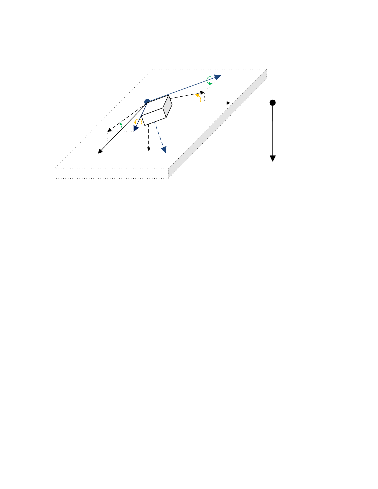
2.1.1Unit Coordinate System ........................................................................................ 6
2.1.2Unit Reference Frames ......................................................................................... 6
2.1.3Angle measurements ............................................................................................ 7
2.1.3.1Tilt Angles ......................................................................................................... 8
2.1.3.2Rotation Angles ................................................................................................. 9
2.1.3.2.1Unit Rotation Angles ................................................................................. 10
2.1.3.2.2Euler Angles ............................................................................................. 11
2.1.3.2.3Gimbal Lock .............................................................................................. 12
2.1.3.3Maximum Gravity Acceleration Error ............................................................... 13
2.1.3.4Practical Recommendations ............................................................................ 13
2.1.3.5Default Settings ............................................................................................... 15
2.2Hardware Block Diagram ........................................................................................... 16
2.3Software Organization ............................................................................................... 16
2.4CAN Interface ............................................................................................................ 17
2.4.1CAN Baud Rate .................................................................................................. 18
2.4.2J1939 Name and Address .................................................................................. 18
2.4.3Slew Rate Control ............................................................................................... 19
2.4.4Network Bus Terminating Resistors .................................................................... 19
2.5Default Settings .......................................................................................................... 19
2.5.1CAN Interface ..................................................................................................... 19
2.5.1.1PGN 61459, Slope Sensor Information, SSI ................................................... 19
2.5.1.2PGN 61481, Slope Sensor Information 2, SSI2 .............................................. 21
2.5.1.3PGN 65256, Vehicle Direction/Speed, VDS .................................................... 22
2.5.1.4PGN 64905, Vehicle Direction/Speed 2, VDS2 ............................................... 23
2.5.2Analog Outputs ................................................................................................... 24
3INCLINOMETER LOGICAL STRUCTURE ....................................................................... 25
3.1Function Block Signals ............................................................................................... 26
3.1.1Undefined Signal ................................................................................................ 26
3.1.2Discrete Signal .................................................................................................... 26
3.1.3Continuous Signal ............................................................................................... 26
3.1.4Signal Type Conversion ...................................................................................... 27
3.1.4.1Discrete to Continuous Conversion ................................................................. 27
3.1.4.2Continuous to Discrete Conversion ................................................................. 27
3.1.4.3Undefined Signal Conversion .......................................................................... 27
3.2Accelerometer ............................................................................................................ 27
3.3Angle Measurement ................................................................................................... 28
3.4Unit Installation .......................................................................................................... 29
3.4.1.1Unit Frame Orientation Examples ................................................................... 30
3.5Sensor Calibration ..................................................................................................... 32
3.6Binary Functions ........................................................................................................ 32
3.7Analog Signal Outputs ............................................................................................... 34
3.8Global Parameters ..................................................................................................... 36
3.9J1939 Network ........................................................................................................... 36
3.9.1ECU Network Parameters ................................................................................... 37

UMAX0608XX‐1000.Tri‐AxialJ1939CANInclinometer.Version9B iv
3.9.2CAN Network Parameters ................................................................................... 37
3.10CAN Input Signal ....................................................................................................... 38
3.11CAN Output Message ................................................................................................ 40
4CONFIGURATION PARAMETERS .................................................................................. 43
4.1Electronic Assistant Software ..................................................................................... 43
4.2Function blocks in EA ................................................................................................ 44
4.3Setpoint File ............................................................................................................... 46
4.4Configuration Example ............................................................................................... 47
4.4.1User Requirements ............................................................................................. 47
4.4.2Configuration Steps ............................................................................................ 47
4.4.3Configuring Analog Signal Outputs ..................................................................... 49
5FLASHING NEW FIRMWARE .......................................................................................... 51
6TECHNICAL SPECIFICATIONS ....................................................................................... 55
6.1Performance Parameters ........................................................................................... 55
6.1.1Angular Measurements ....................................................................................... 55
6.2Power Supply Input .................................................................................................... 55
6.3CAN Output ................................................................................................................ 56
6.4Analog Outputs .......................................................................................................... 56
6.5General Specifications ............................................................................................... 57
6.6Inclinometer Modifications.......................................................................................... 58
6.7Enclosures ................................................................................................................. 58
6.7.1AX060800 ........................................................................................................... 58
6.7.1.1Connector Pinout ............................................................................................ 59
6.7.1.1.1CAN Only .................................................................................................. 59
6.7.1.1.2CAN and Analog Signal Outputs ............................................................... 5 9
6.7.1.2Unit Orientation ............................................................................................... 60
6.7.2AX060806 ........................................................................................................... 60
6.7.2.1Connector Pinout ............................................................................................ 61
6.7.2.2Unit Orientation ............................................................................................... 61
6.8Installation .................................................................................................................. 62
7VERSION HISTORY ......................................................................................................... 63

UMAX0608XX‐1000.Tri‐AxialJ1939CANInclinometer.Version9B Page: 5-66
1 INTRODUCTION
The following user manual describes the architecture, functionality, configuration parameters
and flashing instructions for Tri-Axial J1939 CAN Inclinometers. It also contains technical
specifications and installation instructions for the devices.
The application firmware version numbers described in the user manual, together with the EA
version numbers supporting all inclinometer configuration parameters, are shown on the user
manual front page.
The user manual is usually valid for application firmware with the same major version number
as the user manual. For example, this user manual is valid for any inclinometer application
firmware version 9.xx.
Updates specific to the user manual are done by adding letters: A, B, …, Z to the user manual
version number.
The user should check whether the application firmware installed in the inclinometer is covered
by this user manual. It can be done using Axiomatic Electronic Assistant® (EA) software
through CAN bus.
The inclinometers support SAE J1939 CAN interface. It is assumed, that the user is familiar
with the J1939 group of standards. The terminology from these standards is widely used in this
manual.

UMAX0608XX‐1000.Tri‐AxialJ1939CANInclinometer.Version9B Page: 6-66
2 INCLINOMETER DESCRIPTION
The inclinometer is designed to measures pitch and roll inclination angles in a full ±180-degree
orientation range. The unit can also output gravity angle and unit accelerations in three
orthogonal directions.
The inclinometer transmits data over CAN bus using a standard J1939 protocol. In addition to
the CAN bus, the AX0610000 inclinometer can output data using three analog signal outputs.
The J1939 inclinometer can operate at standard 250kbit/s and 500kbit/s baud rates or non-
standard 667kbit/s and 1000kbit/s (1Mbit/s) baud rates. The required baud rate is detected
automatically upon connection to the CAN network.1
1Inclinometers with firmware V1.xx…6.xx could operate only at 250kbit/s baud rate, and with firmware
V7.xx…8.xx – at 250, 500, and 1000 kbit/s baud rates.
The inclinometer can be configured through a set of configuration parameters to fit the user-
specific application requirements using Axiomatic Electronic Assistant® software.
2.1 Theory of Operation
2.1.1 Unit Coordinate System
The inclinometer uses a standard right-handed Z-down Cartesian coordinate system, see
Figure 1.
X‐Axis
Y‐Axis
Z‐axis
φ‐Roll
θ‐Pitch
Ψ‐Yaw
ax
az
ay
Figure 1. Inclinometer Coordinate System
The arrows in Figure 1 represent a direction of motion that produces a positive change of the
parameter. For ax, ay, az accelerations, the positive acceleration direction is the same as the
axis direction. For 𝜃,𝜙,𝜓 rotation angles the positive direction is contraclockwise about the axis
of rotation (right-hand rule).
The Z-down coordinate system is described by in the SAE J670 standard for automotive
applications. It is used in SAE J1939 slope sensor PGN definitions. This system is similar to
the NED (North-East-Down) coordinate system used in aerospace and navigation, but without
reference to the cardinal directions.
2.1.2 Unit Reference Frames
Several Z-down coordinate systems or frames are used to describe the inclinometer
orientation.

UMAX0608XX‐1000.Tri‐AxialJ1939CANInclinometer.Version9B Page: 7-66
The (X,Y,Z) coordinate system attached to the unit forms a unit or inclinometer frame, see
Figure 2. The original (default) unit frame orientation is shown on the inclinometer label. It can
be changed using configuration parameters to facilitate the unit installation.
X‐Axis
Y‐Axis
Z‐axis
Gravi tyvectoris
coincidentwith
theZ
E
axis
X
E
Y
E
Z
E
Y
M
Z
M
X
M
UnitFrame
MachineFrame EarthFrame
Figure 2. Inclinometer Reference Frames
The (XM,YM,ZM) coordinate system attached to the machine, where the inclinometer is
installed, defines a machine frame. The Earth coordinate system (XE,YE,ZE), aligned with the
Earth gravity, defines the Earth absolute reference frame.
The machine frame is coincident with the Earth reference frame in the initial null-angle position
of the machine when it is leveled on the operation area.
The unit calculates accelerations and angles referred to the machine frame (XM,YM,ZM).
Conversion from the unit frame (X,Y,Z) to the machine frame (XM,YM,ZM) is performed
internally using the unit initial installation angles. They are set to zero by default.
After the inclinometer is installed on the machine at the customer site, the customer can set up
the unit initial installation angles through configuration parameters.
To simplify further description of inclinometer operations, unless specially mentioned, it will be
assumed that the unit frame orientation is original, initial installation angles are zero and all
inclinometer parameters are referred therefore to the unit frame (X,Y,Z).
2.1.3 Angle measurements
The inclination angles are measured by a three-axis MEMS accelerometer, which senses an
acceleration vector 𝑎 in three orthogonal directions X, Y and Z:
𝑎Α
𝑔, (1)
where: 𝑎𝑎
,𝑎,𝑎 – acceleration measured by the unit,
𝐴
𝐴
,
𝐴
,
𝐴
– external acceleration applied to the unit,

UMAX0608XX‐1000.Tri‐AxialJ1939CANInclinometer.Version9B Page: 8-66
𝑔𝑔
,𝑔,𝑔 – gravity acceleration.
The measured acceleration is then transformed into inclination angles based on the
assumption that the only acceleration applied to the unit is the gravity acceleration 𝑔 caused by
the gravity force:
𝑎𝑔, 𝑤ℎ𝑒𝑛
𝐴
0. (2)
The gravity acceleration is then:
𝑔𝑎. (3)
The unit calculates 𝜃 – pitch, 𝜙– roll, and 𝜌 – gravity angles. There is not enough information
based only on the unit accelerations to calculate the 𝜓 – yaw angle.
The pitch and roll angles can be calculated in two different ways: as tilt or rotation angles. The
gravity angle is always a tilt angle.
2.1.3.1 Tilt Angles
The pitch and roll tilt angles define the inclination of the unit relatively to the ground plane. The
gravity angle defines the inclination of the unit relatively the gravity vector.
The pitch 𝜃 and roll 𝜙 tilt angles define the inclination of the unit relatively to the (XE,YE)
ground plane parallel to the Earth surface in the Earth frame (XE,YE,ZE), see Figure 3. The
pitch angle 𝜃 is an angle between the vertical projection XE(XY)* of the unit X axis onto the
ground plane and the X axis. Similarly, the roll angle 𝜙 is an angle between the vertical
projection YE(XY)* of the unit Y axis onto the ground plane and the Y axis.
X‐Axis
Y‐Axi s
Z‐axis
Plane(X
E
,Y
E
)isparalleltotheEarthsurface
θ
t
‐Pitch
φ
t
‐Roll
X
E(XY)
*
Y
E(XY)
*
θ
t
>0
φ
t
<0
Gravityvector
𝑔
iscoincident
withtheZ
E
axis
Y
E
X
E
Z
E
ρ–GravityAngle
Figure 3. Tilt Angles
The angle between the axes projections XE(XY)* and YE(XY)* is not 90° in general case. It is 90°
when the unit is parallel and 180° – when perpendicular to the ground plane.
The gravity angle 𝜌 is an angle between the ZE axis of the Earth frame and the unit Z axis.

UMAX0608XX‐1000.Tri‐AxialJ1939CANInclinometer.Version9B Page: 9-66
The sign of the pitch and roll tilt angles is defined by the right-hand rule and presented by
arrows about the Y and X axes. Since the pitch angle 𝜃 direction in Figure 3 is the same as
the positive direction defined by the yellow arrow about the Y axis, the angle is positive. The
same way, the roll angle 𝜙 direction is the opposite to the positive direction defined by the
green arrow about the X axis. Therefore, the roll angle 𝜙 in Figure 3 is negative.
Depending on the application requirements, pitch and roll tilt angles can be calculated either in
the ±90° or ±180° range using the unit measured accelerations: 𝑎, 𝑎, 𝑎.
For tilt angles in the ±90° range:
𝜃𝑎𝑡𝑎𝑛2𝑔
,𝑔
𝑔
,
𝜃∈90°;90°,(4)
𝜙𝑎𝑡𝑎𝑛2𝑔,𝑔
𝑔
, 𝜙∈90°;90°,
For tilt angles in the ±180° range:
𝜃𝑎𝑡𝑎𝑛2𝑔
,𝑠𝑖𝑔𝑛𝑔∙𝑔
𝑔
,
𝜃∈180°;180°,(5)
𝜙𝑎𝑡𝑎𝑛2𝑔,𝑠𝑖𝑔𝑛𝑔∙𝑔
𝑔
, 𝜙∈180°;180°,
where: 𝑠𝑖𝑔𝑛𝑥1, 𝑥 0
1, 𝑥 0 ,
and: 𝑔𝑎
,𝑔
𝑎
, 𝑔𝑎
.
When measured in the ±90° range, the tilt angles are the angles that a dual-axis inclinometer
(or two single-axis inclinometers placed in orthogonal directions) will measure in the same
position as the unit. They will not detect a roll-over condition.
To detect a roll-over, the gravity angle can be used. The gravity angle is calculated using the
following formula:
𝜌 𝑎𝑡𝑎𝑛2𝑔
𝑔
,𝑔
,
𝜌∈0°;180°
.
(6)
When 𝜌90
°, the roll-over occurs.
When pitch 𝜃 and roll 𝜙 angles are measured in the ±180° range, the tilt angles will detect a
roll-over when: |𝜃|90° 𝑜𝑟 |𝜙|90°, but they will lose a smooth angular transition in the roll-
over points.
When the unit is parallel to the Earth surface, all tilt angles are zero: 𝜃𝜙𝜌0°.
2.1.3.2 Rotation Angles
In opposite to tilt angles that measure an inclination angle of the unit from a certain reference
plane or a vector, the rotation angles measure a rotation angle of the unit about a certain axis.
The unit can measure two types of rotation angles: unit rotation angles and Euler angles.

UMAX0608XX‐1000.Tri‐AxialJ1939CANInclinometer.Version9B Page: 10-66
2.1.3.2.1 Unit Rotation Angles
The unit rotation angles define rotations about the axes in the unit frame (X,Y,Z) the following
way, see Figure 4.
X‐Axis
Y‐Axi s Z‐axis
Plane(X
E
,Y
E
)isparalleltotheEarthsurface
θ
u
‐Pitch
φ
u
‐Roll
X
E(XZ)
*
Y
E(YZ)
*
θ
u
>0
φ
u
<0
Gravityvector
𝑔
iscoincident
withtheZ
E
axis
Y
E
X
E
Z
E
Figure 4. Simple Rotation Angles
The rotation about the Y-axis defines the pitch angle 𝜃 and the rotation about the X axis – the
roll angle 𝜙. The pitch angle 𝜃 is an angle between the horizontal projection XE(XZ)* of the
unit X axis onto the (XE,ZE) plane and the XE axis. Similarly, the roll angle 𝜙 is an angle
between the horizontal projection YE(YZ)* of the unit Y axis onto the (YE,ZE) plane and the YE
axis.
The (XE,ZE) and (YE,ZE) planes are perpendicular to the Earth surface (XE,YE) in the Earth
frame (XE,YE,ZE). The angle between XE(XZ)* and YE(YZ)* is always 90°.
The rotation about the Z-axis (yaw angle) is not shown in Figure 4. It cannot be calculated
based on the gravity acceleration 𝑔.
The sign of the pitch and roll angles is defined by the right-hand rule and presented by the
arrows about the Y and X axes. Since the pitch angle 𝜃 direction in Figure 4 is the same as
the positive direction defined by the yellow arrow about the Y axis, the angle is positive. The
same way, the roll angle 𝜙 direction is the opposite to the positive direction defined by the
green arrow about the X axis. Therefore, the roll angle 𝜙 in Figure 4 is negative.
The unit rotation angles are calculated using the following formulas:
𝜃𝑎𝑡𝑎𝑛2𝑔,𝑔
,
𝜃∈180°;180°,(7)
𝜙𝑎𝑡𝑎𝑛2𝑔,𝑔
,
𝜙∈180°;180°,
where: 𝑔𝑎
,𝑔
𝑎
, 𝑔𝑎
.
The roll-over condition is observed when: |𝜃|90° or |𝜙|90°.
When the unit is parallel to the Earth surface, the unit rotation angles are zero: 𝜃𝜙0°.

UMAX0608XX‐1000.Tri‐AxialJ1939CANInclinometer.Version9B Page: 11-66
The unit rotation angles do not uniquely define the unit angular position in space. If this is
required, the Euler angles should be used.
2.1.3.2.2 Euler Angles
The Euler angles are coordinate system rotation angles performed in a specific order to rotate
the unit from its original position, parallel to the Earth surface, to its current position.
The Euler angles: 𝜃 and 𝜙, together with the 𝜓, are rotation angles about the ZE, YE* and X
axes performed in a standard (yaw, pitch, roll) rotation sequence used in aerospace and
defined in SAE J670 standard for automotive applications, see Figure 5.
X‐Axis
Y‐Axi s
Z‐axis
Plane(X
E
,Y
E
)isparalleltotheEarthsurface
X
E
Y
E
Z
E
θ
E
‐Pitch
φ
E
‐Roll
X
E
*
Y
E
*
Z
E
*
ψ
E
‐Yaw
1.ψ
E
<0
2.θ
E
>0
3.φ
E
<0
Gravityvector
𝑔
iscoincident
withtheZ
E
axis
Figure 5. Euler Angles
The first rotation defines the 𝜓 – yaw angle. It is performed about the ZE axis of the Earth-
fixed coordinate system (XE,YE,ZE) from the XE axis to the XE* axis. An intermediate coordinate
system (XE*,YE*,ZE*) is a Z-down coordinate system whose XE* and YE* axes are parallel to the
ground plane (XE, YE), with the XE* axis aligned with the vertical projection of the X axis onto
the ground plane. Since the yaw rotation 𝜓 on Figure 5 is opposite to the positive rotation
direction, shown by the red arrow about the ZE axis, the resulted angle is negative.
The second rotation defines the 𝜃 – pitch angle. It is performed about the YE* axis of the
intermediate coordinate system (XE*,YE*,ZE*) from the XE* axis to the X axis. The pitch rotation
𝜃 on Figure 5 is in the positive rotation direction, defined by the yellow arrow about the YE*
axis, and the resulted angle is therefore positive.
The final third rotation defines the 𝜙 – roll angle, as a rotation about the X axis from the YE*
axis to the Y axis. The roll rotation 𝜙 on Figure 5 is negative. It is performed in the direction
opposite to the positive rotation direction shown by the green arrow about the X axis.
The set of the three: yaw, pitch, and roll Euler angles fully represents the angular position of
the inclinometer in space.
There is not enough information for the unit to calculate the yaw angle 𝜓, based only on the
accelerometer data.

UMAX0608XX‐1000.Tri‐AxialJ1939CANInclinometer.Version9B Page: 12-66
The Euler angles are calculated using the following formulas:
𝜃𝑎𝑡𝑎𝑛2𝑔,𝑔
𝑔
,
𝜃∈90°;90°,(8)
𝜙𝑎𝑡𝑎𝑛2𝑔,𝑔
,
𝜙∈180°;180°,
where: 𝑔𝑎
,𝑔
𝑎
, 𝑔𝑎
.
The roll angles for both: the unit rotation and Euler angles are the same: 𝜙𝜙.
The roll-over condition is observed when: |𝜙|90
°.
When the unit is parallel to the Earth surface, the Euler angles are zero: 𝜃𝜙0°.
2.1.3.2.3 Gimbal Lock
The formulas for the roll angle 𝜙 and 𝜙 are numerically unstable when both: 𝑔𝑔
0.
This condition, called a gimbal lock, happens when the unit is placed in the vertical position
with the X axis parallel to the gravity vector, see Figure 6. When this happens, the unit
effectively loses one degree of freedom and the roll angles 𝜙 and 𝜙 become undefined and
can take any random value.
Z‐axis
Y‐Axis
X‐Axis
Plane(X
E
,Y
E
)isparalleltotheEarthsurface
Gravi tyvector
𝑔
iscoincident
withtheZ
E
axis
Z‐axis
Y‐Axi s
X‐Axis
Figure 6. Gimbal Lock
The same condition occurs with the pitch angle 𝜃 when both: 𝑔𝑔
0.
The gimbal lock should be avoided in the inclinometer initial installation position. It should be
also avoided in the inclinometer working range when it leads to unstable angular
measurements.
The user can avoid the gimbal lock condition by changing orientation of the unit frame (a
coordinate system attached to the unit) using configuration parameters when necessary.

UMAX0608XX‐1000.Tri‐AxialJ1939CANInclinometer.Version9B Page: 13-66
2.1.3.3 Maximum Gravity Acceleration Error
All angular measurements are based on the assumption that the only acceleration applied to
the unit is the gravity acceleration 𝑔, see (2). This is not entirely true when the inclinometer is
installed on a moving machine and is experiencing various external accelerations. These
accelerations will affect the angular calculations and, at some point, will make the accuracy of
the calculations inacceptable.
To monitor the validity of the angular calculations, the inclinometer is calculating the Gravity
Acceleration Error 𝛿 as a difference between the measured gravity acceleration 𝑔 and its
expected value:
𝛿1
𝑔
𝑔
𝑔
(9)
When the difference exceeds a predefined value 𝛿𝛿
, the angular calculations are
considered invalid and the inclinometer sets the error state in the Angular Figure of Merit.
The Maximum Gravity Acceleration Error 𝛿
is set by the user normally above the
expected external accelerations at the customer site during normal operation conditions.
Please remember that even when 𝛿𝛿
, the rated inclinometer static parameters
including accuracy are not guaranteed during external accelerations. The 𝛿
only sets a
threshold to notify the user that the external accelerations are too high for the angular
measurements.
2.1.3.4 Practical Recommendations
In the beginning, the user defines an inclinometer position on the machine, direction of the
measurement angle or two angles in orthogonal directions, and the angular ranges.
It is important to understand that the inclinometer calculates angles based on the gravity
acceleration and the angles are measured between the inclinometer unit frame or machine
frame and the Earth absolute reference frame (XE,YE,ZE) where the gravity acceleration vector
is uniquely defined.
The inclinometer can measure only pitch 𝜃 and roll 𝜙 angles. It cannot measure the yaw angle
𝜓, since the yaw angle is in the plane perpendicular to the gravity acceleration in the Earth
absolute reference frame (XE,YE,ZE) and therefore cannot be detected by an accelerometer.
The user starts with aligning the inclinometer unit frame with the Earth absolute reference
frame at the inclinometer expected position on the machine. This is done by pointing the unit
frame Z-axis down, making it coincident with the gravity acceleration vector, and then aligning
the unit pitch 𝜃 and roll 𝜙 angles with the required measurement angles. The user can do this
either by mechanically rotating the inclinometer housing on the machine or by changing the
unit frame orientation using inclinometer configuration parameters.
The vertical mount inclinometer modifications can be also used if the inclinometer housing is
installed in the vertical position on the machine.1

UMAX0608XX‐1000.Tri‐AxialJ1939CANInclinometer.Version9B Page: 14-66
1 The vertical mount inclinometer modifications are the legacy products that were designed for a vertical
inclinometer installation in the past when the unit frame orientation was not configurable. Starting from
V5.0 firmware, they do not have any advantages over the regular (horizontal mounting) inclinometers
with the unit frame orientation configured for the vertical installation.
After the inclinometer position and the unit frame orientation are defined, the user should
choose the type of the angles, since both: tilt and rotation angles have their pros and cons for
angular measurements.
Table 1. Tilt and Rotation Angles
Inclination Angles Advantages Disadvantages
Tilt, ±90° Range Numerically stable in the whole
angular range
Smooth angular transition inside
the measurement range
±90° range for pitch and roll angles
No roll-over detection
Tilt, ±180° Range Numerically stable in the whole
angular range
±180° range for pitch and roll
angles
Roll-over detection
Abrupt angular transition inside the
measurement range in roll-over
points
Unit Rotation
Angles
Smooth angular transition inside
the measurement range, except
for the gimbal lock points.
±180° range for pitch and roll
angles
Roll-over detection
Numerically unstable pitch and roll
angles in gimbal lock points
Euler Angles Smooth angular transition inside
the measurement range, except
for the roll angle in gimbal lock
points
±180° range for the roll angle
Roll-over detection
Uniquely define the unit angular
position in space
±90° range for pitch angle to avoid
ambiguity in angular rotations
Numerically unstable roll angle in
gimbal lock points
For single and dual-axis measurements, when the measurement range is not above ±90°, the
tilt angles in the ±90° range are recommended, see Figure 7 and Figure 8. They are
numerically stable and have a smooth angular transition inside the measurement range. If
necessary, a roll-over can be monitored by the gravity angle.
For single-axis measurements, when the measurement range is above ±90, the rotation angles
are recommended. For unit rotation angles, either pitch or roll angle can be used depending on
the position of the unit on the machine. For Euler angles, the roll angle can be used, since it
covers the entire ±180° range.
For dual-axis measurements with the measurement range above ±90, both: tilt angles in the
±180° range or rotation angles can be used, see Figure 8. If a smooth angular transition inside
the measurement range is not necessary, the tilt angles in the ±180° range are recommended
due to their numerical stability in the whole measurement range.

UMAX0608XX‐1000.Tri‐AxialJ1939CANInclinometer.Version9B Page: 15-66
Single‐Axis
|Angle|>90°
TiltAngle ±90°
EulerorUnit
RotationAngle
Yes No
Angleinpitch
direction
UnitRotationAngle
Yes
No
Figure 7. Single-Axis Measurements
In case it is necessary to get the ±180° range for both: pitch and roll angles with a smooth
angular transition, the unit rotation angles should be used. Otherwise, the Euler angles are
preferred, since they have a gimbal lock only for the roll angle, the pitch angle is numerically
stable in the whole measurement range.
Dual‐Axis
|Angle|>90°
Ti ltAngle ±90°
Angularposition
ins pace
Smoothangular
transition
No
No
No
Ti ltAngle±18 0°
Pitchangle
±180°
EulerAngle UnitRotationAngle
No
Yes
Yes
Yes
Yes
Figure 8. Dual-Axis Measurements
The Euler angles are the angles of choice when it is necessary to determine the unit angular
position in space. The yaw angle is then resolved by an external magnetic or GPS sensor.
Even when the Euler angles are not used to calculate pitch and roll angles, they are still used
internally to compensate the unit initial installation angles.
2.1.3.5 Default Settings
Inclinometers: AX060800, AX060830, AX061000, AX060806, AX060810, AX060807,
AX060811 measure tilt angles in the ±90° range by default1.

UMAX0608XX‐1000.Tri‐AxialJ1939CANInclinometer.Version9B Page: 16-66
The legacy vertical mounting modifications: AX060808, AX060838, originally designed for
single-axis measurements in the roll angular direction, measure Euler angles by default.
1Inclinometers with V1.xx firmware measure tilt angles in the ±180° range by default.
2.2 Hardware Block Diagram
The inclinometer contains a three-axis MEMS accelerometer, which senses acceleration in
three orthogonal directions: X, Y, and Z.
The outputs of MEMS accelerometer are processed by a 32-bit microcontroller to calculate the
unit accelerations and inclination angles. The inclination angles are then output to CAN bus
together with all other necessary information, see Figure 9.
EMIFilter.
TransientandReverse
PolarityProtection
BAT+
BAT‐
PowerSupply
3DAccelerometer ARMCortex‐M3
Microcontroller
CAN
CAN_HI
CAN_LO
CAN_SHIELD*
*CAN_SHIELDisabsentinAX060806andAX060807units.
**AnalogOutputsblockandAOUT1...3,AGND1...2arepresentonlyinAX061000units.
AnalogOutputs**
AOUT1**
AOUT2**
AOUT3**
AGND1**
AGND2**
PTCResettableFuse
Figure 9. The Inclinometer Hardware Block Diagram
The inclinometer has a wide range of protection features including a transient and reverse
polarity protection, see Technical Specifications section.
2.3 Software Organization
The Tri-Axial J1939 CAN Inclinometer belongs to a family of Axiomatic smart controllers with
configurable internal architecture. This architecture allows building a controlling algorithm
based on a set of predefined internal configurable function blocks without the need of custom
software.

UMAX0608XX‐1000.Tri‐AxialJ1939CANInclinometer.Version9B Page: 17-66
The user can configure the inclinometer structure and function blocks using PC-based
Axiomatic Electronic Assistant® (EA) software through CAN interface, without disconnecting
the inclinometer from the user’s system.
The inclinometer application firmware can be updated the same way using EA in the field, see
Flashing New Firmware section.
2.4 CAN Interface
The inclinometer CAN interface is compliant with Bosch CAN protocol specification, Rev.2.0,
Part B, and the following J1939 standards:
Table 2. J1939 Standard Support
ISO/OSI Network Model
Layer J1939 Standard
Physical J1939/11 – Physical Layer, 250K bit/s, Twisted Shielded Pair. Rev.
SEP 2006
J1939/15 - Reduced Physical Layer, 250K bits/sec, Un-Shielded
Twisted Pair (UTP). Rev. AUG 2008
J1939/14 - Physical Layer, 500 Kbps. Rev. OCT 2011
J1939/16
–
A
utomatic Baud Rate Detection Process. Rev. NOV 2018
Data Link J1939/21
–
Data Link Layer. Rev. DEC 2006
The inclinometer supports Transport Protocol for Commanded Address
messages (PGN 65240), ECU identification messages -ECUID (PGN
64965), and software identification messages -SOFT (PGN 65242). It
also supports responses on PGN Requests (PGN 59904).
Please note that the Proprietary A PGN (PGN 61184) is taken by
A
xiomatic Simple Proprietary Protocol and is not available for the user.
Network J1939, Appendix B – Address and Identity Assignments. Rev. FEB 2010
J1939/81 – Network Management. Rev. MAR2017
The inclinometer is an Arbitrary Address Capable ECU. It can
dynamically change its network address in real-time to resolve an
address conflict with other ECUs.
The inclinometer supports: Address Claimed Messages (PGN 60928),
Requests for Address Claimed Messages (PGN 59904) and
Commanded Address Messages (PGN 65240).
Transport N/A in J1939
Session N/A in J1939
Presentation N/A in J1939
Application J1939/71 – Vehicle Application Layer. Rev. SEP 2013
The inclinometer can receive application-specific PGNs with input
signals and transmit application-specific PGNs with up to ten output
signals. All application-specific PGNs are use
r
-programmable.
J1939/73
–
A
pplication Layer
–
Diagnostics. Rev. FEB 2010
Memory access protocol (MAP) support. DM14, DM15, DM16
messages are used by EA to program configuration parameters.

UMAX0608XX‐1000.Tri‐AxialJ1939CANInclinometer.Version9B Page: 18-66
2.4.1 CAN Baud Rate
The inclinometer can operate at J1939 standard 250kbit/s and 500kbit/s baud rates. It can also
run at 667kbit/s and at 1Mbit/s – the maximum baud rate supported by the CAN inclinometer
hardware.1
1Inclinometers with firmware V1.xx…6.xx could operate only at 250kbit/s baud rate, and with firmware
V7.xx…8.xx – at 250, 500, and 1000 kbit/s (1Mbit/s) baud rates.
The baud rate selection is performed automatically upon connection to the CAN network using
passive and active automatic baud rate detection process described in J1939/16. Once
detected, the baud rate is stored in non-volatile memory and used on the next inclinometer
power-up.
The baud rate detection can be disabled for permanently installed units to maintain the desired
baud rate on the CAN network.
2.4.2 J1939 Name and Address
Before sending and receiving any application data, the inclinometer claims its network address
with a unique J1939 Name. The Name fields are presented in the table below:
Table 3. J1939 Name Fields
Field Name Field Length Field Value Configurable
Arbitrary Address Capable 1 bit 1 (Capable) No
Industry Group 3 bit 3 (Construction Equipment) No
Vehicle System Instance 4 bit 0 (First Instance) No
Vehicle System 7 bit 0 (Nonspecific System) No
Reserved 1 bit 0 No
Function 8 bit 136 (Slope Sensor) No
Function Instance 5 bit 52 – AX060800, AX060806, AX060807,
AX060808, AX060830, AX060838,
AX060810, AX060811;
72
–
A
X061000.
No
ECU Instance 3 bit 0 (First Instance) Yes
Manufacturer Code 11 bit 162 (Axiomatic Technologies Corp.) No
Identity Number 21 bit Calculated on the base of the
microcontroller unique ID
No
2 Axiomatic proprietary values for Tri-Axial J1939 CAN Inclinometers.
The user can change the inclinometer ECU Instance using EA to accommodate multiple units
on the same CAN network.
The inclinometer takes its network ECU Address from a pool of addresses assigned to self-
configurable ECUs. The default address can be changed during an arbitration process or upon
receiving a commanded address message. The new address value will be stored in a non-
volatile memory and used next time for claiming the network address. The ECU Address can
also be changed in EA.

UMAX0608XX‐1000.Tri‐AxialJ1939CANInclinometer.Version9B Page: 19-66
2.4.3 Slew Rate Control
The inclinometer has an ability to adjust the CAN transceiver slew rate for better performance
on the CAN physical network, see J1939 Network function block for further details.
2.4.4 Network Bus Terminating Resistors
The majority of inclinometers do not have an embedded 120 Ohm CAN bus terminating
resistor. Check the Technical Specifications section for the particular part number.
If not internally installed, the terminating resistors should be installed externally on both ends of
the CAN twisted pair cable according to the J1939/11(15) standards to avoid communication
errors.
Even if the length of the CAN network is short and the signal reflection from both ends of the
cable can be ignored, at least one 120 Ohm resistor is required for the majority of CAN
transceivers to operate properly.
2.5 Default Settings
The inclinometer is shipped with the following pre-configured settings to transmit angular data
on the CAN bus.
2.5.1 CAN Interface
By default, the inclinometer angular data is transmitted in a standard PGN:
PGN 61481, Slope Sensor Information 2, SSI21.
The inclinometer is also pre-configured the way that it can send data in:
PGN 61459, Slope Sensor Information, SSI;
PGN 65256, Vehicle Direction/Speed, VDS;
PGN 64905, Vehicle Direction/Speed 2, VDS2.
The user should use EA to activate sending the appropriate preconfigured PGNs by changing
the Transmission Enable configuration parameter from No to Yes, see CAN Output Message
function block. Any other user-defined PGNs can be configured by EA as well.
1In firmware V1.xx, AX060800, AX060806, AX060807 transmit angular data in SSI PGN by default.
2.5.1.1 PGN 61459, Slope Sensor Information, SSI
This PGN provides measurements of the vehicle pitch and roll angles and a measurement of
the vehicle pitch rate. It has the following parameters:
Transmission Repetition Rate: 10 ms
Data Length: 8
Default Priority: 3
Parameter Group Number: 61459
Start Position Length Parameter Name SPN
1-2 2 bytes Pitch Angle 3318

UMAX0608XX‐1000.Tri‐AxialJ1939CANInclinometer.Version9B Page: 20-66
Start Position Length Parameter Name SPN
3-4 2 bytes Roll Angle 3319
5-6 2 bytes Pitch Rate 3322
7.1 2 bits Pitch Angle Figure of Merit 3323
7.3 2 bits Roll Angle Figure of Merit 3324
7.5 2 bits Pitch Rate Figure of Merit 3325
7.7 2 bits Pitch and Roll Compensated 3326
8 1 byte Roll and Pitch Measurement Latency 3327
Parameter Name: Pitch Angle
Data Length: 2 bytes
Resolution: 0.002 deg/bit, -64 offset
Data Range: -64 to 64.51 deg Operational Range: same as data range
Type: Measured
Parameter Name: Roll Angle
Data Length: 2 bytes
Resolution: 0.002 deg/bit, -64 offset
Data Range: -64 to 64.51 deg Operational Range: same as data range
Type: Measured
Parameter Name: Pitch Rate (Not used by the inclinometer. Populated with 0xFFFF)
Data Length: 2 bytes
Resolution: 0.002 deg/sec per bit, -64 offset
Data Range: -64 to 64.51 deg
/
sec Operational Range: same as data range
Type: Measured
Parameter Name: Pitch Angle Figure of Merit
Data Length: 2 bits
Bit 2 Bit 1
0 0 Pitch angle fully functional. Data is within sensor specification.
0 1 Pitch angle degraded. Data is suspect due to environmental
conditions.
1 0 Erro
r
1 1 Not available
Type: Status
Parameter Name: Roll Angle Figure of Merit
Data Length: 2 bits
Bit 2 Bit 1
0 0 Roll angle fully functional. Data is within sensor specification.
0 1 Roll angle degraded. Data is suspect due to environmental
conditions.
1 0 Erro
r
1 1 Not available
Type: Status
Parameter Name: Pitch Rate Figure of Merit (Not used by the inclinometer. Populated with 11b)
Data Length: 2 bits
Bit 2 Bit 1
0 0 Pitch rate fully functional. Data is within sensor specification.
Table of contents
Other AXIOMATIC Measuring Instrument manuals
Popular Measuring Instrument manuals by other brands

Hanna Instruments
Hanna Instruments HI 8010 user manual

Turner
Turner AquaFlash user manual

Siemens
Siemens FS20 Application guide

Frient
Frient Electricity Meter Interface installation guide

Mid-Continent Instruments
Mid-Continent Instruments 4300-4 Series Installation manual and operating instructions

Endress+Hauser
Endress+Hauser Cerabar PMC71B Brief operating instructions