7
SPECIFICATIONS
MONITOR
TFT Panel: New Grade A LCD
LCD Size: 5-Inch Diagonal
Display Format: 16:9
Resolution: 800 x 480
Brightness: < 450 CD/M2
Viewing Angles: 70° Left/Right/Up/Down
Video System: Auto PAL/NTSC Select
Video Connect: 3 x 4-Pin (Female)
Reverse Trigger: Yes, Each Input
Monitor View: Normal/Mirror Image Select
Buttons: Illuminated
Guidelines: Selectable On/Off (Camera 2 Only)
Audio: On Board Speaker
Menu: OSD
Operating Temp: -20°C to +70°C
Power Input: 12-32V DC (Negative Ground)
Brackets: U-Mount, Glass Mount
Dimensions: 132W x 95H x 26D mm (excluding bracket)
Finish: Matt Black Rubber
HEAVY DUTY CAMERA
Image Sensor: 1/3” Sony CCD
Auto Lens: f2.9mm
Electronic Shutter: Auto
Vertical Viewing Angle: 120°
Horizontal Viewing Angle: 90°
Signal System: PAL
Resolution: 700 TV Lines
Sync System: Internal
Orientation: Mirror Image
Night Vision: Yes, 18 LED
Illumination: 0 Lux with IR on
Ingress Protection: IP69K
Operating Temperature: -20°C ~ 70°C
Dimensions: 70W x 45H x 60D mm (Excl Bracket)
Connection: Terminated 4-Pin Male
Power Supply: 12V DC (From Monitor)
DUAL MOUNT CAMERA
- Image Device: 1/3” CMOS
- Diagonal Viewing Angle: 165°
- Horizontal Viewing Angle: 120°
- Signal System: PAL
- Effective Pixels: 640 x 480
- Resolution: 480 TV Lines
- Compatibility: All Monitors with RCA Input
- Lens: Full Glass
- Orientation: Mirror Image
- Guidelines: Selectable On/Off
- Night Vision: 0.2 Lux
- Ingress Protection: IP67
- Integrated Microphone: No
- Operating Temp: -20 to 70°
- Power Consumption: 90-300mA
- Connection: Mini 4 Pin Terminated RCA (F), RCA (M) to 4 Pin Adaptor
- Lead: 6M Mini 4 Pin to RCA (M)
- Dimensions: 16.5W x 16.5H x 23D mm (Excluding Bracket)
- Power Supply: 12V DC
TRAILER QUICK CONNECT
Curly Cable Length: 0.5m (Original State)
4.0m (Elongated)
Mounting Plate: 5-Pin (Male) Metal Plug with
Weather Cover
Brackets: 2 x Metal Plug Mounting Brackets
Cable (Monitor Side): 10m Terminated to 4-Pin (Male)
(Trailer Plug to Monitor)
Cable (Camera Side): 15m Terminated to 4-Pin (Female)
(Camera to Trailer Plug)
INCLUDES
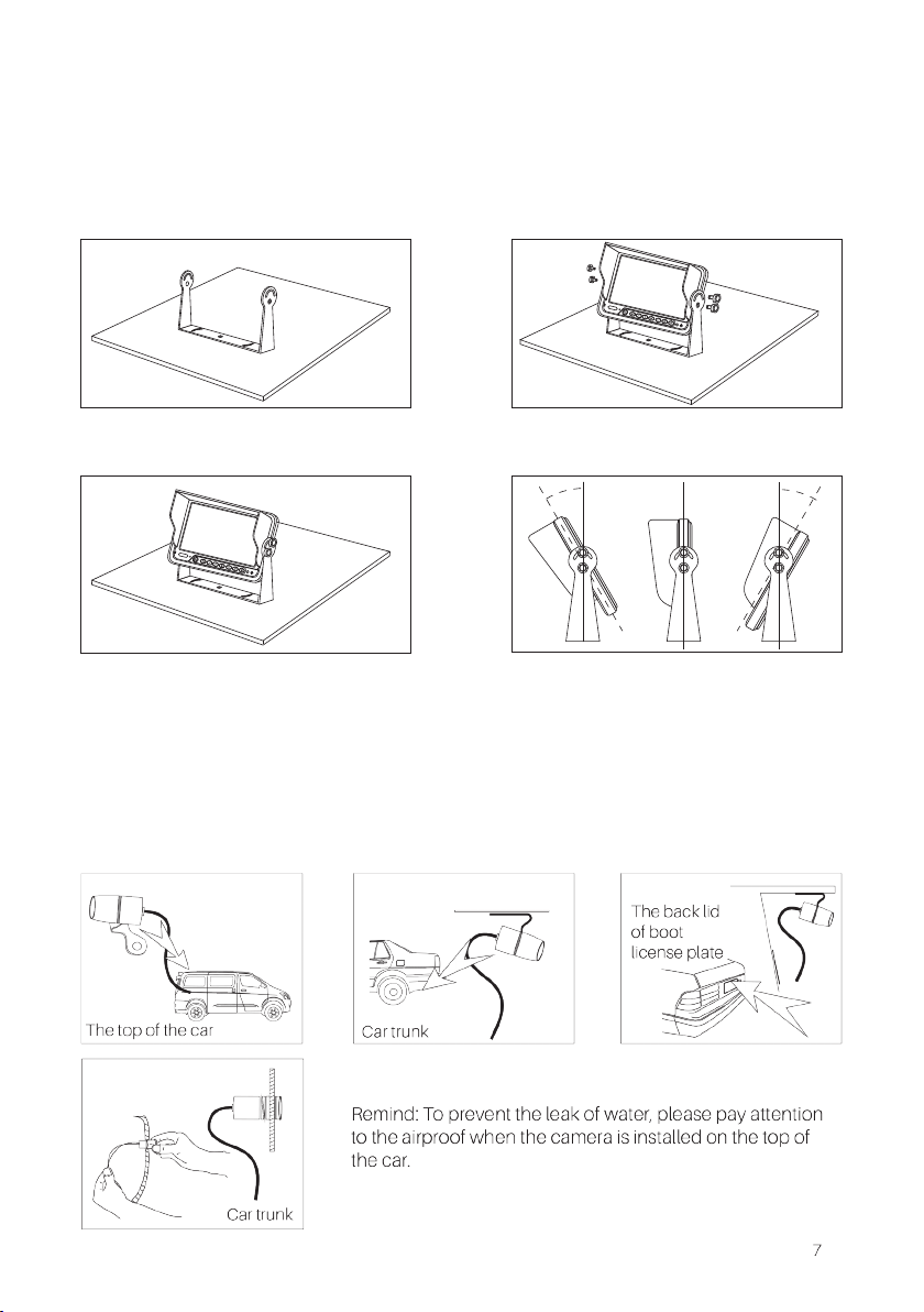
U-Shape Mount
Power Cable Assembly
Sunshade
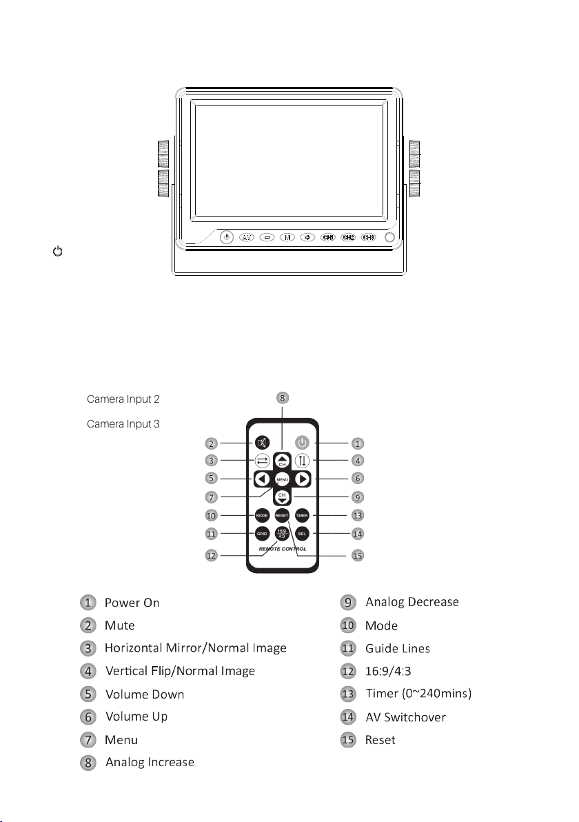
Remote Control
Glass Mount Bracket
HEAVY DUTY CAMERA (White)
15m 4-Pin (Male) to 4-Pin (Female) Extension Cable
Mounting Bracket
Sunvisor
DUAL MOUNT CAMERA
15m 4-Pin (Male) to 4-Pin (Female) Extension Cable
Installation Hardware
Metal Hole Saw for Bumper Fit Installation
6m Video Cable (RCA M to RCA M)
TRAILER QUICK CONNECT
Curly Cable (0.5m - Original State & 4.0m - Elongated)
2 x Metal Plug Mounting Brackets
10m Terminated to 4-pin male connector(to plug into monitor)
0.3m Terminated to 4-pin female connector(to plug into camera)
RCA(M) to 4-pin(M) Adaptor cable