ASSEMBLY
5
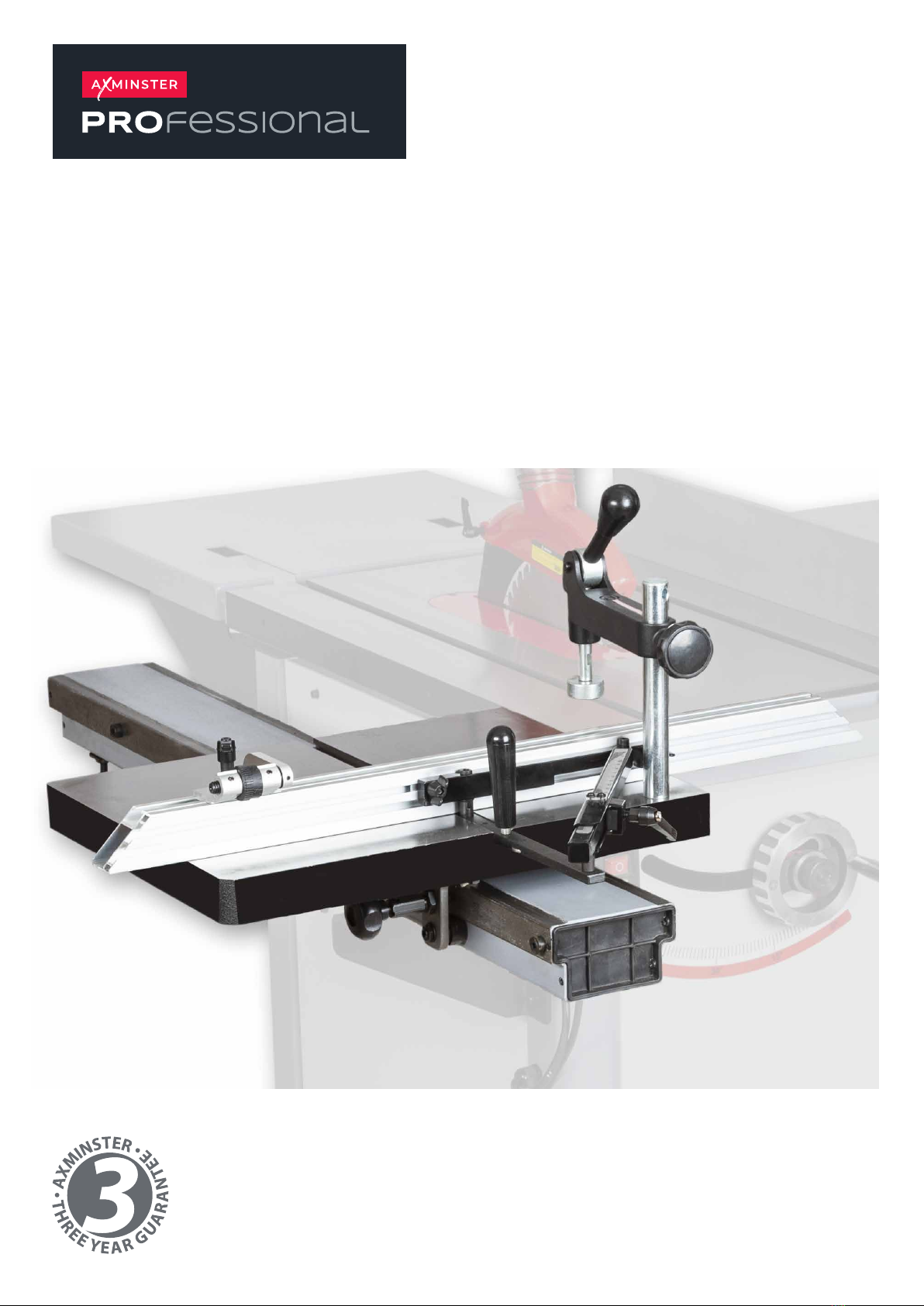
Fitting the Angle Gauge
Fitting the Angle Gauge Sliding Table Fence
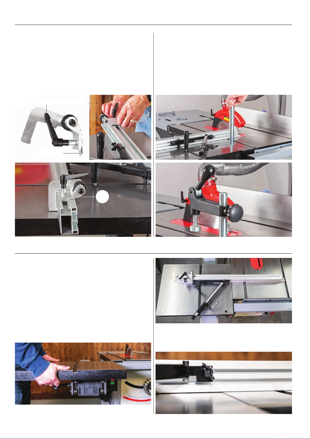
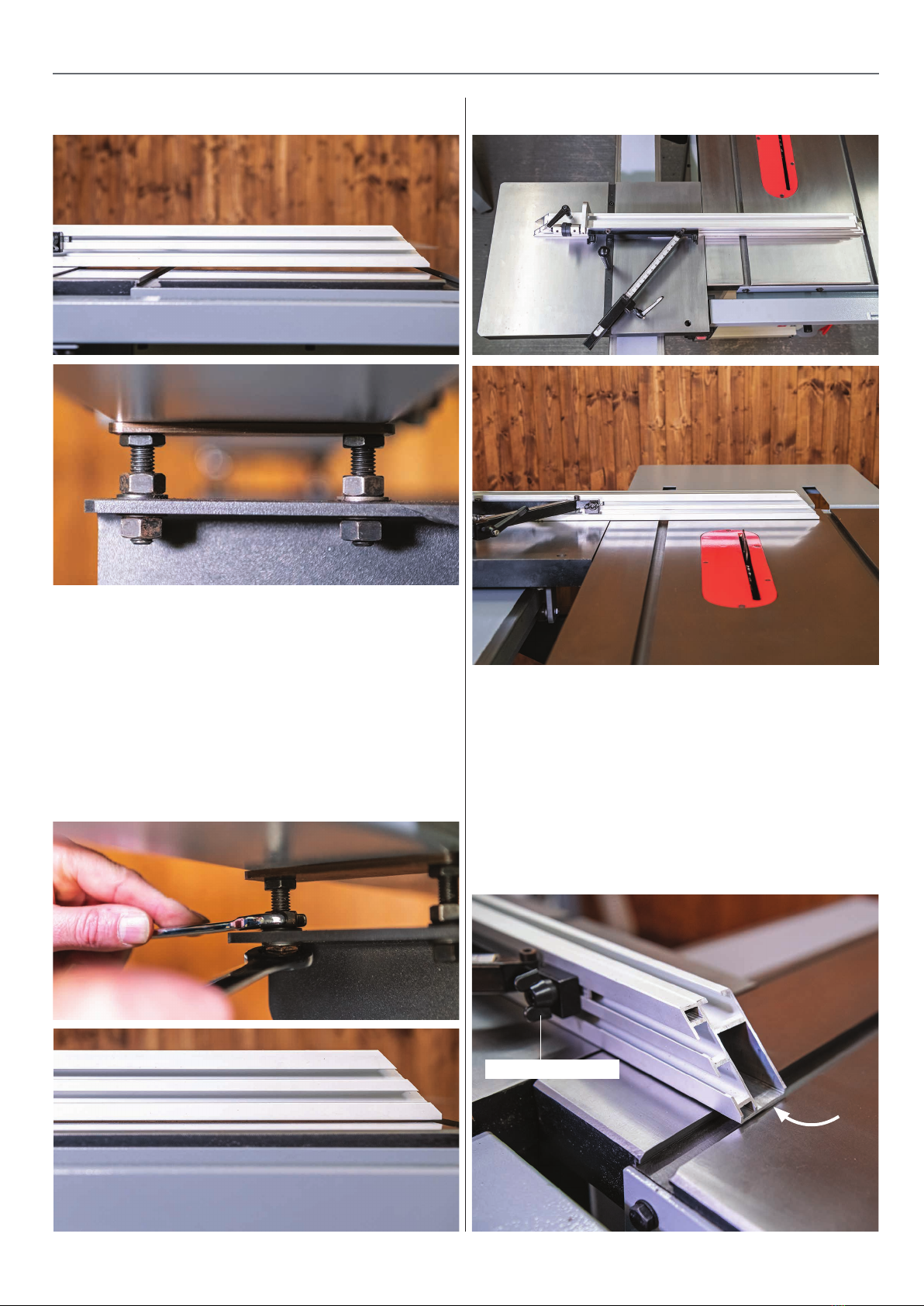
2. Place a straight edge a crossed both tables, see fig 12.
Loosen the support rail (B) locking nuts below the angle
brackets (A), see fig 09 and adjust the four upper nuts
above angle brackets to raise or lower the support rail
assembly, see fig 13. NOTE: make small adjustments
until the sliding table (C) is 0.5mm above the main table.
Once complete tighten the locking nuts to secure the
support rail in place. See set up / alignment on page 6
for levelling the sliding table to the main table in more
detail.
Fig 12-13
Adjusting nut
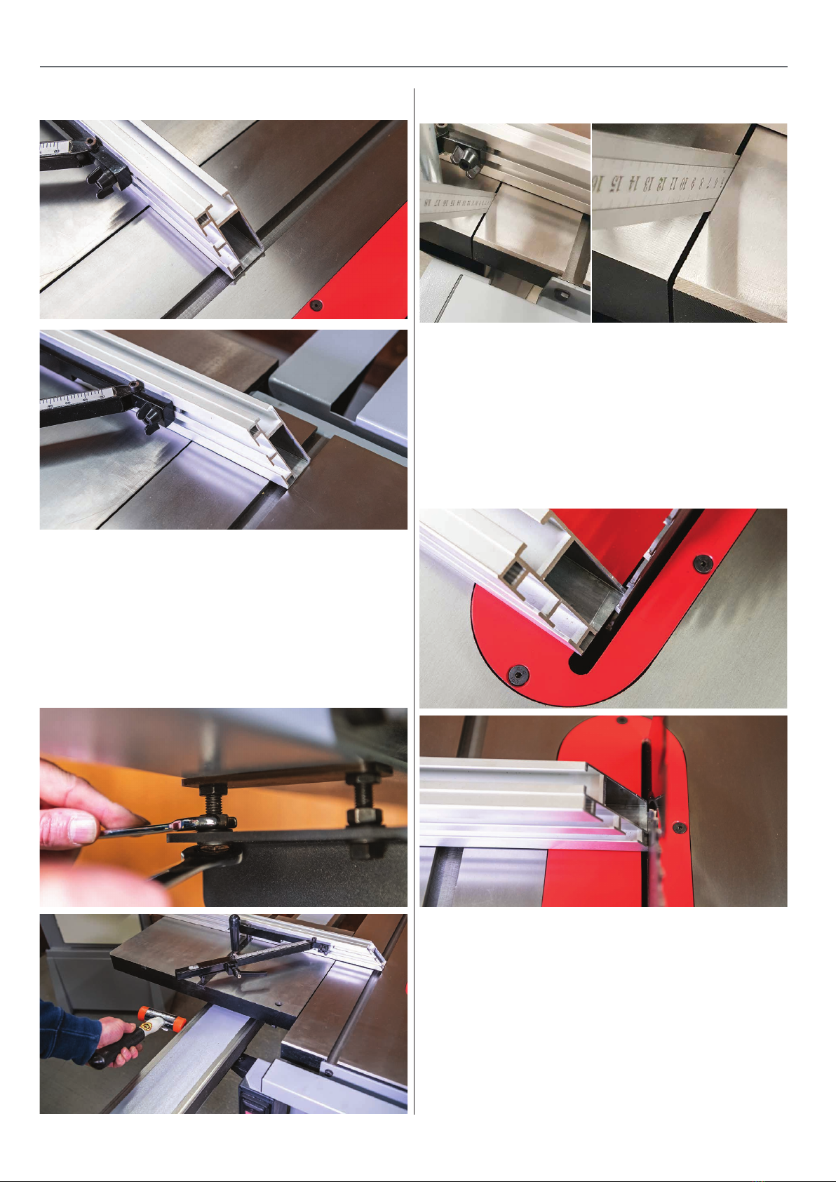
1. Locate the angle gauge (H), using a hex key remove the
cap head bolt in the sliding tables ‘T’ slot and place safely
to one side, see fig 14.
2. Slide the angle gauge (H) into the sliding tables ‘T’ slot.
Note: there are two threaded holes in the tables ‘T’ slot,
enabling the angle gauge to be set in two positions,
see fig 15. This gives extra support for different lengths of
timber.
Fig 14
Cap head bolt
Fig 15-16
3. Line up the recessed hole in the angle gauge support
bar with one of the threaded holes in the table and
replace the cap head bolt you removed earlier, see fig 16.
Threaded holes
recessed hole
1. Find the sliding table fence (G), loosen the two
thumb screws on the angle gauge (H) to give sufficient
clearance to the ‘T’ bolt clamps, see fig 17.
2. Line up the ‘T’ slot in the aluminium fence (G) with the
first ‘T’ bolt clamp and slide on the fence. Repeat for the
remaining ‘T’ bolt clamp, see 18-19. Nip-up the thumb
screws to lock the fence in place.
H
Fig 17-18-19
‘T’ Bolt clamp
Thumb screw
G
Continues over...