Axminster UJK Pro Router Table User manual

Cast Iron Top Kit Code 717127
Laminated Top Kit Code 719240
Original Instructions
AT: 04/08/2020
BOOK REF: 104390
BOOK VERSION: 04
Pro Router Table
Hole assembly instructions including the UJK
table tops, fence assembly, table inserts and
other accessories

Index of Contents
2
• Introduction 03
• What’s Included 04-05-06-07
• Optional Accessories 08-09-10-11-12
• Kit Specification 13
• General Instructions for 230V Machines 13
• General Safety Instructions 14
• Assembly 15-16-17-18-19-20-21-22-23-24
• Illustration & Parts Description 25
• Mounting the Router to the Universal Base Plate 26-27
• Mounting the Router to the 10mm Table Inserts 28-29-30
• General Guide to Router Cutters 31-32
• Exploded Diagram/Parts LIst 33-34-35-36-37
• Notes 38-39
Fully read manual
and safety instructions
before use
Eye protection
should be worn
Ear protection
should be worn
Dust mask
should be worn
The symbols below advise the correct safety procedures when using this machine.
Axminster Tools & Machinery Ltd
Axminster Devon
EX13 5PH UK
axminster.co.uk
Type Router Table
Model UJK
EC DECLARATION OF CONFORMITY
MACHINERY DIRECTIVE,UJK ROUTER TABLE,
Axminster Tools and Machinery Ltd
declares that the attachment described
under Technical Data is in compliance with:
2006/42/EC
declares that the machinery described:-
Declaration of Conformity
Signed
Andrew Parkhouse
Operations Director

3
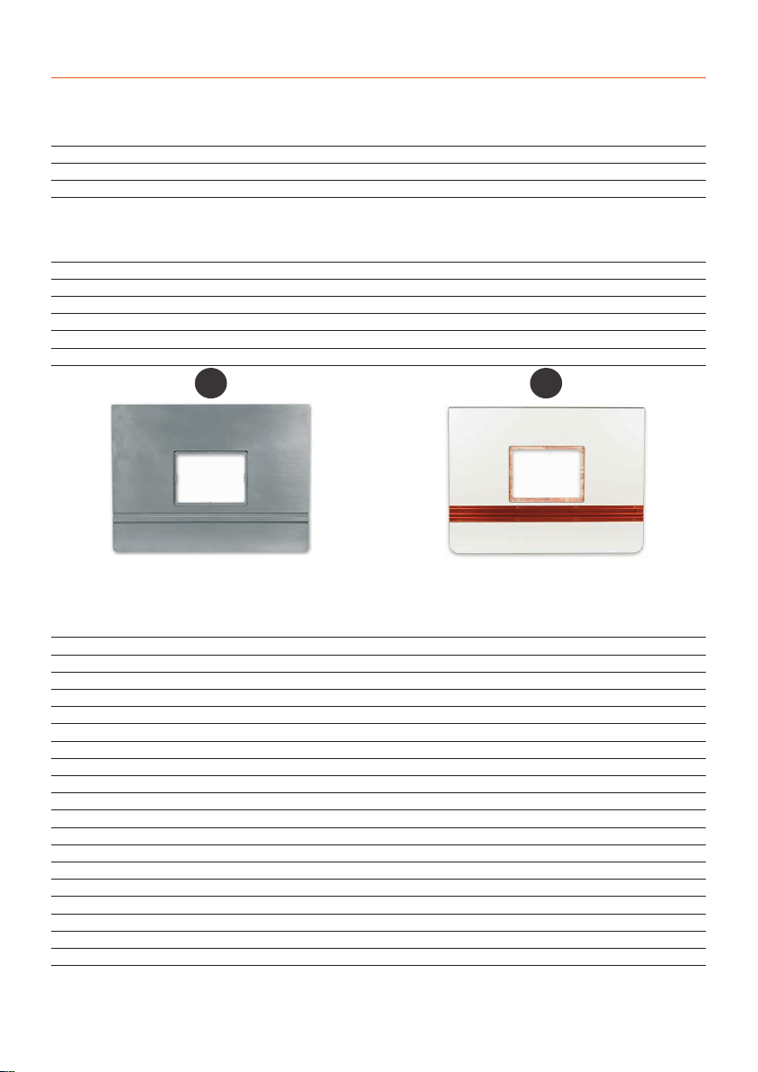
The UJK professional router table is a solid, dependable
unit that will give many years of useful service.The benefits of
using cast iron for the manufacture of machine tables are well
known especially where vibration damping and stability are
paramount.The quality of the surface grinding on this table is
superb, offering little resistance when passing stock across the
table during use. If you have room in your workshop for a full
sized router table, you will wonder how you managed without
one.There are many complex routing operations that can only
be carried out using a table set-up.The aperture in the table
top is designed to accept our router elevator and when fitted
with this unit you will have yourself an excellent versatile set-
up.Top measures 812 x 610mm.
Introduction
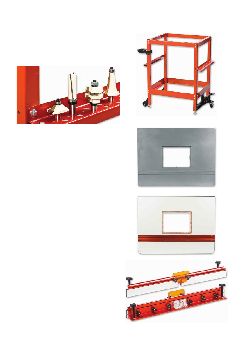
The Professional Laminated router table is high grade birch
ply with a hard wearing, low friction, phenolic laminated sur-
face.The ply core ensures the top will remain flat throughout its
working life, while the laminated top ensures workpieces glide
smoothly. An extruded aluminium track inset into the tabletop
includes a standard 19mm track for the use of a mitre fence and
a T-track slot for other jigs and accessories.The 230 x 306mm
central aperture will accept any of the UJK router table inserts
as well as the UJK router elevator.The top measures 800 x
600mm and is pre-drilled to fit the UJK Professional router table
leg stand, fence assembly or optional dust collection box
.
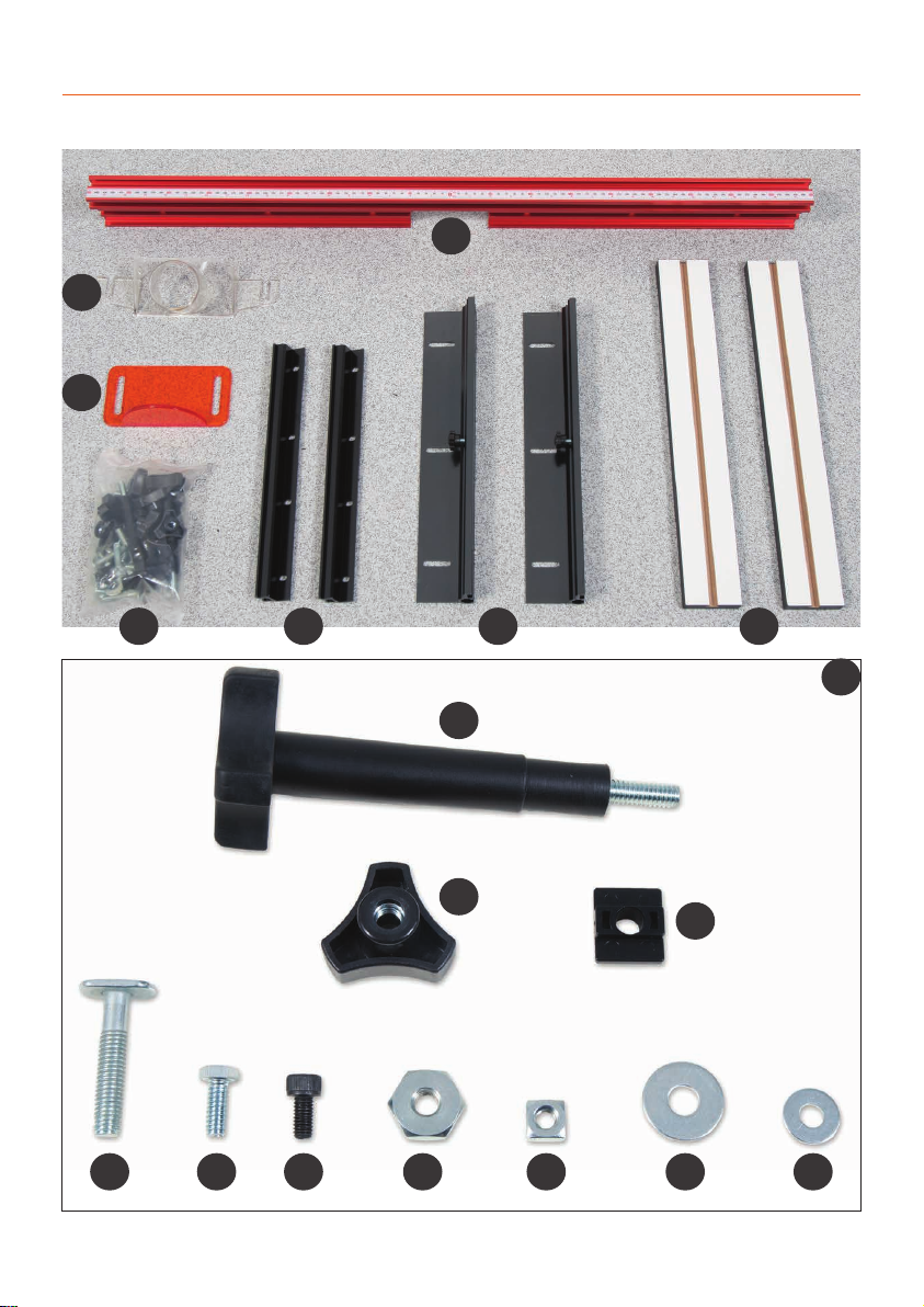
The fence is a superb quality single aluminium section
supplied with a transparent dust port for efficient extraction
from above the table. Provision is made for the fitting of guards
and accessories with a T-slot at both the top and front of the
fence.An adjustable transparent guard is included for your
safety. Adjustable scales are provided for attachment at either
side of the table and the fence is attached to these and locks
into place at the required position.A scale is also provided for
the top of the fence with the zero position at the centre.
Adjustable in-feed and out-feed fences attach to either side of
the aluminium section and the central aperture can be opened
and closed according to the diameter of the cutter in use.
Fence measures 904 x 90mm high.
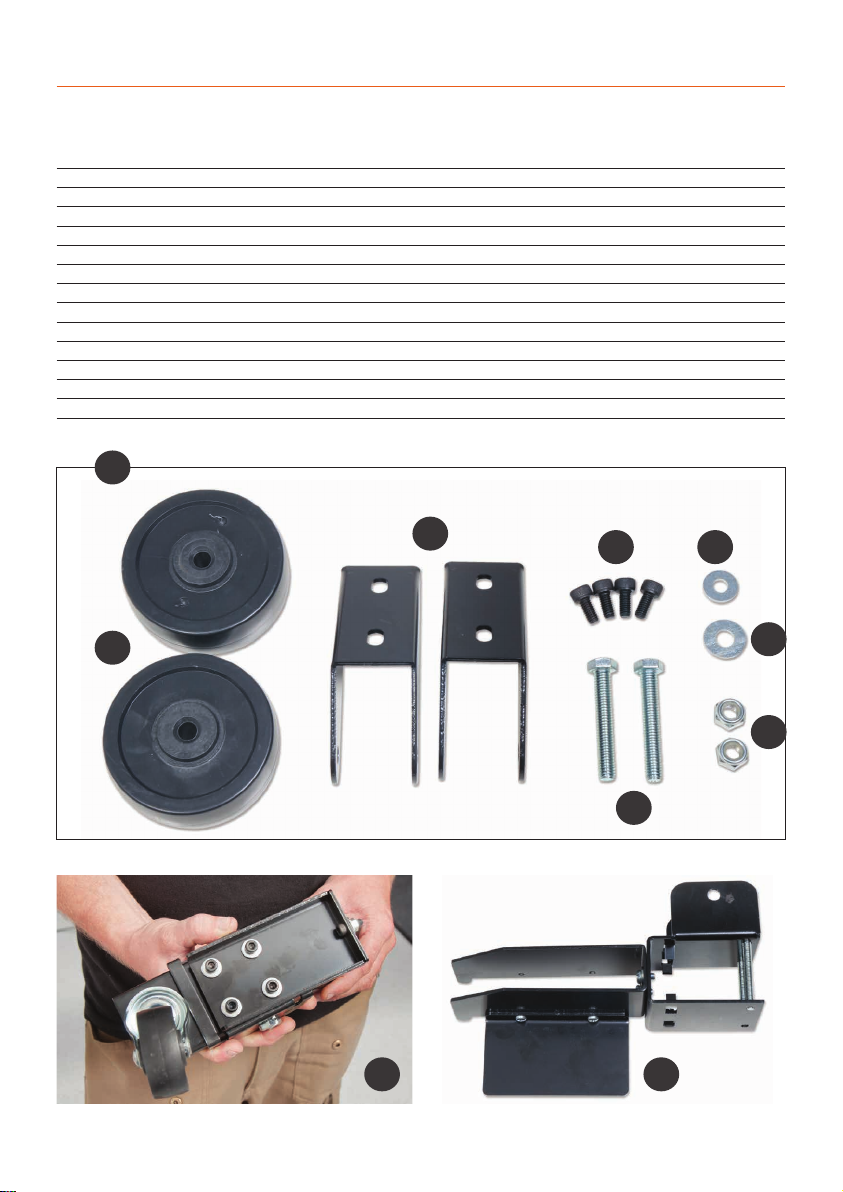
The leg stand is of sturdy construction with a foot operated
retractable castor for excellent mobility around the workshop.
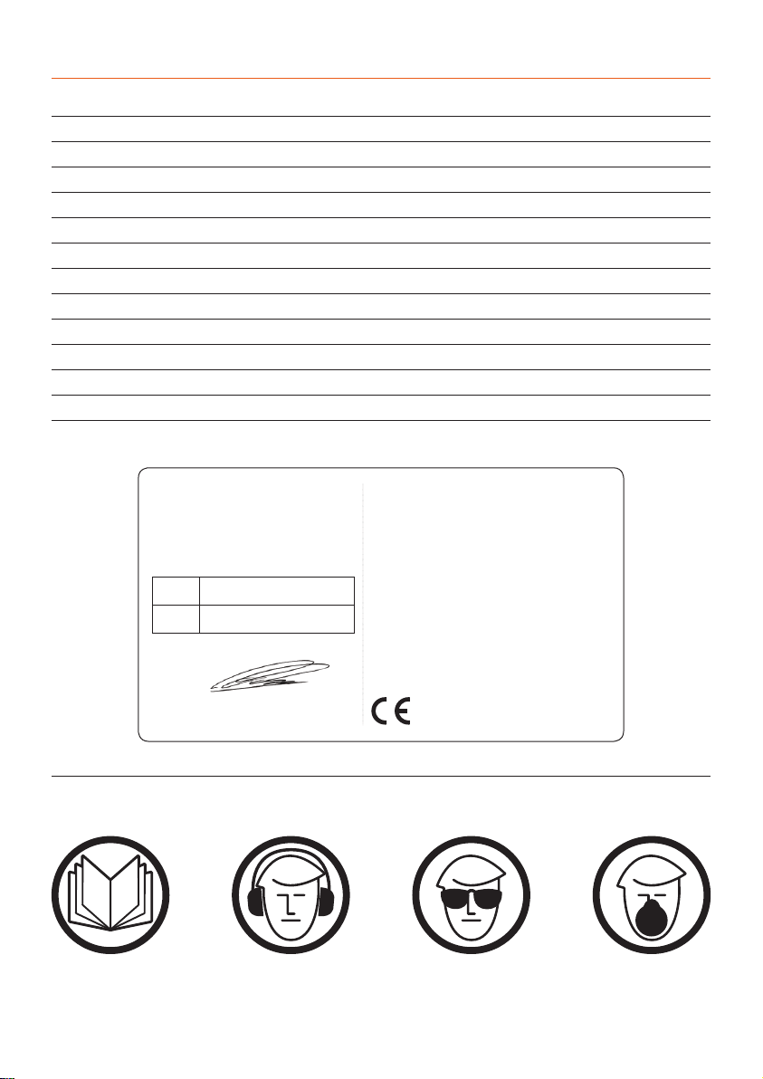
A neat rack is provided for keeping your most popular router
cutters to hand and provision is made for storage of the
supplied mitre fence assembly. Stand height including cast
iron top 930mm.

What’s Included
4
Quantity Item Part Code
502536
Bag 1 Containing:
40 No Bolts (M6x12mm) 1
40 No Flat Washers M6 2
2 No Round Head Screws (M4x20mm) 3
4 No Adjustable Feet 4
4 No Upright Supports A
2 No Upper Side Panels (Long) B
2 No Upper Side Panels (Short) C
2 No Lower Support Brackets (Long) D
2 No Lower Support Brackets (Short) E
2 No Cutter Holders F
1 No Mitre Fence/ Extension G
2 No Bolts (M6x30mm)
2 No M6 Washers
2 No Wing Nuts
1 No Wheel Support Bracket H
UJK Router Table Leg Stand
A
B
CF
G
GH
4
D
E

What’s Included
5
Rear Wheel Assembly
Quantity Item Part Code
502536
Bag 2 Containing:
2 No Wheels a
2 No Wheel Brackets b
4 No Hex Bolts (M6x12mm) c
2 No Bolts (M8x50mm) d
4 No M6 Washers e
4 No M8 Washers f
2 No M8 Nuts g
1 No Mobility Wheel Assembly J
1 No Mitre Fence Tool Rest K
a
bc e
f
g
d
J K
I

What’s Included
6
Bag Containing Code: 502535-102543
10 No Countersink Phillips Screws (M6x20mm)
6 No Hex Bolts (M6x16mm)
6 No M6 Washers
6 No Spring Washers
10 No M6 Nuts
UJK Router Table Tops
Quantity Item Part Code
1 No UJK Pro Cast Iron router table top A502535
1 No UJK Pro Laminated router table top B102543
A
UJK Pro Cast Iron Table Top
B
UJK Pro Laminiated Table Top
Quantity Item Part Code
508273
1 No Fence K
1 No Extraction Moulding L
1 No Dust Shield M
1 No Bag Containing N
2 No Locking Handle Knob (5/16”) a
8 No M8 Locking Knobs b
2 No Fence Spacers c
8 No ‘T’ Bolts (M8x43mm) d
6 No Hex Screws (M6x12mm) e
8 No Hex Bolts (1/4 x 5/8” f
2 No Lock Hex Nuts (5/16”) g
6 No Square Nuts 1/4” h
10 No M8 Flat Washers i
6 No Flat Washers (M6) j
2 No Fence Fixing Brackets O
Fence Fixing Brackets with Scale P
2 No Adjustable Wood Faces Q
UJK Fence Assembly

What’s Included
7
K
L
M
N O P Q
a
bc
degh i j
N
f

Optional Accessories
8
1) UJK QuickStop
(Code 502569)
•A hinged stop to fit the UJK router tables.
•An excellent device for stopped
chamfers or rebates.
•Attaches to the top of the router
table fence.
•Simply flips up out of the way when not required.
502566
502567
502565
105932
502748
502525
951187
2) UJK 10mm Aluminium Router
Table Insert c/w Universal Base
(Code 502748)
UJK 10mm Aluminium Table Insert
(Code 105932)
• Threaded lead-in pin.
• To fit 230 x 306mm aperture.
• Twist lock insert ring supplied with wrench.
3) Router Table Inserts
• A range of central inserts for the
• Axminster or UJK router elevator
• Also suitable for UJK aluminium and phenolic router table
insert plates.
• Sizes include 12.6mm, 38mm, 63.4mm plus a guide bush
adaptor.
• Blank insert available for making your own hole size.
• Available as a set of four or individually.
(Code 502565) 12.6mm
(Code 502566) 38mm
(Code 502567) 63.4mm
(Code 951187) Blank Insert
(Code 502525) Guide Bush Adaptor
4) Vertical Feather Boards
(Code 502751)
• Gives downward pressure against workpiece.
• Excellent for safer routing.
5) Horizontal Feather Boards
(Code 502750)
• Holds workpiece against fence.
• Excellent for safer routing.
• Use as singles or stacked for more support.
502751
502750

Optional Accessories
9
6) UJK Router Elevator
(Code 502701)
The UJK router elevator is a logical solution for fast,
accurate production on many router table installations.
This compact design was developed by us to fit straight
into our own router tables and most table set-ups can
accommodate this size of insert (305 x 229 x 6mm).The unit
can be made to fit flush into the tabletop by the provision
of levelling screws at each corner of the table insert. Height
adjustment is carried out by inserting a handle through a
measurement dial set into the machine table. Each rotation
of the handle raises or lowers the cutter by exactly 2mm
and the integral scale is graduated into increments
enabling very accurate adjustments to be carried out.
7) UJK Dust
Extraction Box
(Code 502538)
• Dust collection device.
• Efficient extraction from above and below the table.
•Access door with magnetic catch.
•63mm extraction hose included.
•100mm outlet.
Dust extraction from a router table can be difficult and for it to
work effectively it needs to extract from both above and below
the table. Designed to fit the UJK Pro and Compact router
tables this device fits below the table top enclosing the router.
It could also be fitted to other custom made tables of your
own design.The 100mm diameter outlet on the back also
incorporates a 62mm inlet and hose which enables extraction
from both above and below the table simultaneously. An
access door is provided on the front with a magnetic closure
enabling access to your router for adjustments if required.
Measures 330 x 260 x 350mm high with an access aperture of
225 x 170mm.
Continues Over...
8) UJK Off Set Bars for Router Tables
(Code 103561)
A pair, these H-section extrusions fit behind the outfeed
fence of the UJK router table fence. Once in position they
give you an exact 1mm offset between the infeed and
outfeed fences. Their clever design means you can rotate
each extrusion by 180° and reinsert them in position to
achieve an exact 2mm offset.

Optional Accessories
10
9) UJK Extension for Cast Iron Router Table
(Code 103551)
Made specifically for the UJK Professional Router Table, this
extension provides vital extra support when machining
wide workpieces such as raised panels for cupboard doors.
It is 810mm in length, running along the entire front edge
of the table. Fixing is just a simple matter of attaching a
bracket on either side, on the underside of the table using
3 cap-head screws per side.
The extension slides in and out of the brackets, on strong
rectangular section bars. Going from zero to 260mm, at its
maximum, it effectively gives you approximately 610mm
from the centre of the router cutter to the edge of the
extension.The top edge of the extension is a low friction
material, ensuring that your work glides smoothly.
10) UJK Digital Height Gauge
(Code 103655)
The UJK Digital Height Gauge is an indispensable
measuring tool for the accurate setting of cutting depths,
in particular router cutters and saw blades.
The body is cast iron, with machined feet that form a
reference surface. It is stable and can stand upright without
additional support. It is equally accurate both vertically and
horizontally.The horseshoe shaped body measures 54mm
between the legs with an internal height of 80mm.The
main feature is its highly accurate digital scale unit, with an
LCD screen offering a read-out in either metric or imperial.
The display has a resolution of 0.01mm or 0.001 inches.
The digital read-out tells you precisely how deep your saw
blade or router cutter is going to cut.With a measuring
speed of 1.5 milliseconds, it is somewhat faster than
making a guess with a ruler. You can zero the digital
read-out at any point, allowing relative adjustment. It is
particularly handy to hold the bar in contact with the blade
or cutter and gradually increase the cutter height until the
display reaches the desired depth.Used horizontally, you
can measure or adjust a router table fence relative to the
cutter.The UJK Digital Height Gauge will also measure a
mortice to a depth of 99mm.

Optional Accessories
11
10) UJK Precision Mitre Gauge Fence & Flip Stop
(Code 104579)
This mitre gauge system is made from 5mm steel plate and
features positive stops at 0°, 22.5°, 30°, 45°, 60°, 67.5° and
90°. Simple to adjust with a spring loaded plunger stop and
able to be set at any other angle between 0-90° as required.
The other main feature is the anodised alloy fence, fitted
with an adjustable flip-over length stop.This fence can be
slid along the gauge body by releasing two thumb screws.
The 320mm bar can be fitted to a standard 3/4”x 3/8”(19
x 9.5mm) table slot; the locking washer can be removed if
required.
This mitre gauge will improve accuracy when cross or mitre
cutting on many machines or router tables.
14) UJK Router Table NVR Switch
(Code 101607)
This UJK Professional Blank Laminated Table This NVR
Switch clamps directly to the leg stand of the UJK
Professional Router Tables and provides an independent
switching arrangement for your router.
Offering the protection of No Voltage Release and with a
protected 13A socket, it is perhaps the best way to use your
router in a table.You need to able to“latch”your router’s
switch in the“on”position. Supplied with 2m of cable with
a moulded 13A plug and a steel clamping bracket.

Optional Accessories
12
15) UJK Professional Coping Sled
(Code 102946)
When profiling the end grain of a narrow workpiece on the
router table,you need a way of holding the workpiece.This
is particularly relevant if your workpiece is narrower than
the gap in your router fence.The UJK Coping Sled holds
the key to working safely, securely and achieving accurate
results.
Developed and extensively tested by UJK, this Coping Sled
will transform the way you make end grain cuts for rail
and stile doors, tenons and many other joints.If you are
intending to make cabinet doors on your router table, the
Coping Sled is invaluable.It is by far the best was to secure
your workpiece, offering perfect results with a high degree
of safety.The Coping Sled takes the stress out of the pro-
cess. It ensures your workpiece is square to the table’s mitre
slot and that it guides smoothly across the router bit.
The Coping Sled secures your workpiece both horizontally
and vertically. A slotted top plate holds the work firmly
against the sled’s rear fence.This plate prevents kickback
and easily adjusts for material up to 135mm wide. Two
vertical clamps prevent the workpiece lifting during the
cut.The position of the foremost clamp, close to the point
of cut, significantly reduces vibration.The maximum work-
piece thickness is 40mm.
To prevent tear-out at the end of the cut, the Coping
Sled has a 45mm wide x 22mm deep nylon fence. Unlike
aluminium, nylon will not damage your router cutter.You
can use the fence as a spelcher if you wish or use an off-cut
to prevent tear-out. The fence includes a sliding flip-stop for
repeat cuts. A T-slot cutter is available should you wish to
make a replacement or custom wooden fence.
On the underside of the 10mm thick, low-friction
baseboard is a 19 x 9.5mm (3/4”x 3/8”) mitre slot bar. It
will fit both plain and T-slot mitre slots.Two grub screws,
150mm apart, allow adjustment for zero play in the slot.The
bar has a choice of five positions to accommodate a wide
variety of router tables.
Two large rubberised handles provide a firm safe grip for
complete control.The design allows you to position the
handles directly over the work.The sled’s handles make
sure both your hands remain a safe distance from the
router bit. A clear,full width Plexiglas shield acts as a chip
deflector.

Kit Specification
General Instructions for 230V Machines
13
Code 717127
Rating Trade
Table Size 812 x 600mm
Table Height 930mm
Fence Size 904 x 90mm
Dust Extraction Outlet 62mm
UJK Professional Router Table with Cast Iron Table Top
Code 719240
Rating Trade
Table Size 800 x 600mm
Table Height 890mm
Fence Size 904 x 90mm
Dust Extraction Outlet 63mm
UJK Professional Router Table with Laminated Table Top
Good Working Practices/Safety
General Advice
Mains Powered Tools/ Primary Precautions
General Safety Instructions
The following suggestions will enable you to observe good
working practices, keep yourself and fellow workers safe
and maintain your tools and equipment in good working
order.
WARNING! KEEP TOOLS AND
EQUIPMENT OUT OF THE REACH
OF YOUNG CHILDREN
If you are totally unfamiliar with the use of a power
router, please seek some basic tuition and advice from an
informed, qualified source. An amateur woodworker or
hobbyist just starting out is advised to undertake a short
course on the use of woodworking machines run by a
professional woodworker.These are often offered by your
local authority as evening classes.
These tools are supplied with a moulded 13 Amp. plug and
3 core power cable. Before using the tool inspect the cable
and the plug to make sure that neither are damaged. If
any damage is visible have the tool inspected/repaired by
a suitably qualified person. If it is necessary to replace the
plug, it is preferable to use an ‘unbreakable’type that will
resist damage on site.Only use a 13 Amp plug, make sure
the cable clamp is tightened securely and check that a 13
Amp fuse is fitted.It is also recommended that a switched
power outlet is used. If extension leads are to be used,
carry out the same safety checks on them, and ensure that
they are correctly rated to safely supply the current that is
required for your machine.
•Carefully study and observe the safety instructions issued
with the router being used in the table.
•In addition, the following precautions, specific to the use
of router tables,should be adhered to.
•Ensure that the router is securely fixed to the router table,
both when first commissioned and periodically thereafter.
•Fix the router table to a firm base such as a workbench or
a heavy table. If the table is attached to a false base this in
turn should be firmly fixed to a workbench or other solid
surface.
• Always wear appropriate safety equipment such as safety
goggles or face shield,dust mask and ear defenders.Ties,
loose clothing and jewellery are all potential safety hazards
and should be avoided.
•The router table is intended for cutting timber and plas-
tics only, do not use it with other materials. Long lengths of
timber will need to be supported on both the in-feed and
out-feed sides of the table.
•Timber should be fed into the cutter from the right hand
side of the table, as indicated on the safety label attached
to the fence. A push block or custom made work holder
should be used when cutting small pieces.
•Router cutters should be installed correctly in the router
with the recommended minimum length of shaft engaged
in the collet and the collet tightened to the correct degree.
•When making any adjustments to the router, such as
changing the cutter, ensure that the router is switched off
and the power cable is removed from the power supply
before proceeding.

General Safety Instructions
14
1. Make sure that the operator has been properly trained
and has read and understands the Owner’s Manual before
operating any machinery.
2. Be sure to read, understand, and follow all instructions,
warnings, and safety guidelines supplied with your router,
3.
Keep the work area well lit,clean, and free of debris.
4.
STAY ALERT! Give your work your undivided attention.
Even a momentary distraction can lead to serious injury.
5.
Do not wear loose clothing,gloves, bracelets,neck-laces,
or other protection devices.Wear protective hair covering
to contain long hair and wear nonslip footwear.
6.
Keep hands and other body parts well away from bits
or cutting tools.When working close to the cutting tool,
always use a feather board or push-stick to hold or guide
the workpiece. Do not clear chips and sawdust away with
hands; use a brush.
7.
Fine particulate dust is a carcinogen that can be
hazardous to health. Always work in a well ventilated area
and whenever possible use a dust collector to minimize
health hazards.
8.
Be sure the router is running up to speed before feeding
the workpiece.
9.
Use a suitable support if stock does not have a flat
surface.
10.
Keep children and visitors at a safe distance when the
router is in operation - do not permit them to operate the
router and/or table.
11.
Childproof and taper proof your shop and all
machinery with locks, mater electrical switches and
switch keys, to prevent unauthorised or unsupervised use.
12.
Secure the table to a work surface and never stand or
lean on it. Serious injury can occur if the table is tipped or if
unintentional contact is made with the spinning router bit.
13.
Keep all guards and safety devices in place and in good
working order. If a guard must be removed for maintenance
or cleaning make sure it is properly reinstalled before using
the machine again.
14.
Hold the workpiece firmly against the table and use
suitable support if the workpiece does not have a flat
surface.
15.
Feed the stock into the bit against the rotation direc-
tion of the bit. Never run the stock between the fence and
the bit.
16.
Do not operate with a damaged cutter in the router.
17.
Always disconnect the router from the power source
before changing accessories or before performing any
maintenance and adjustments or if the machine will be left
unattended.
18.
Be sure that all adjustment tools,wrenches, or other
clutter are removed from the table surface and safely
stored before routing.
19.
Make sure the router’s switch is in the “OFF” position
before plugging in to a power source.
20.
Avoid working from awkward or off-balance positions.
Do not overreach and always keep both feet firmly on the
floor.
21.
Never leave the router unattended while running or
with the power“ON”.
22.
Do not use this router table for any purposes other
than its intended use.If used for other purposes, Axminster
Tool Centre disclaims any real or implied warranty and
holds itself harmless for any injury which may result from
such use.

Assembly
15
UJK Router Table Leg Stand Assembly
Step 1 Locate the bag of bolts (M6x12mm) (1), flat washers
M6 (2), upright supports (A) and the upper side panels
(long) (B). Secure one of the side panels (B) to the top of
the upright supports (A) with the M6 bolts and washers, see
fig 01. (lightly tight)
Step 2 Locate one of the lower support brackets (long) (D)
and secure to the upper supports (A) as shown in fig 02.
Repeat for the opposite side.
Fig 01
1 2
B
A
Fig 02
1 2
D
Step 3 Locate the upper side panels (short) (C) and lower
support brackets (short) (E). Secure the lower support
brackets (E) to the two front panels you already assembled
and lightly tighten, see figs 03-04.
D
Fig 03-04
E
E
Step 4 Secure the upper side panels (C) to the front panels
and lightly tighten. (See fig 05) Now go round the stand
and tighten all the M6 bolts, see fig 06.
Fig 05
Fig 06
C
C
Continues Over...

Assembly
16
Step 7 Locate the wheel support bracket (H), lineup holes
in the bracket with the threaded holes to the base of the
upright supports (A) and secure using four M8 bolts and
washers (1-2), see fig 07-08.
Fig 07-08
Fig 09-10
H
1 2
4
Step 8 Locate the four adjustable feet (4),turn over the
stand assembly and screw each foot into the
base of the upright supports, see figs 09-10.
(Leave loose for adjustment later)
Mobility Wheel Assembly
Step 9 Locate the mobility wheel assembly (J),remove the
five Hex bolt and washers and place safely aside. Separate
the back plate from the main assembly, place the back plate
inside the support bracket (H) and line up the holes.
Offer up wheel assembly to the front of the support
bracket (H), lining up the holes, secure using the Hex bolts
you removed earlier, see figs 11-13.
Fig 11-12
Hex bolt/washers
Wheel assembly
Back plate
H

Assembly
17
Fig 13
Secure the end of the back plate to the lower support
bracket (E) and then turn the stand upright.
E
Rear Wheel Assembly
Step 10 Locate the wheel brackets (b), the four M6 Hex bolt
(c) and M6 washers (e). Lineup the wheel bracket (b) holes
with the threaded holes to the base of the upright support
(A) and secure using two Hex bolts and washers (c and e).
(See fig 14) Repeat for the opposite side,see fig 15.
Fig 14
Fig 15
b
c e
Step 11 Turn over the stand, locate the wheels (a), M8x50
bolts (d), M8 washers (f ) and M8 nuts (g). Position the
wheel into the wheel bracket (b), insert a M8 washer two
either side of the wheel and line up the holes. Insert the M8
bolt (d) through the wheel bracket and secure using a M8
nut (g), see figs 16-17.
DO NOT OVERTIGHTEN!
OTHERWISE THE WHEEL WILL
NOT ROTATE FREELY.
Fig 16-17
d
f
b
a
Repeat for the other side see image below.
Continues Over...

Assembly
18
Adjust the foot (4) until it’s level with the top of the wheel
(a), see image below.Repeat for the other side.
4
Step 12 Turn the stand upright,place a level on top of the
stand and adjust the nuts on the front feet (4) until the
stand is level and the mobility wheel operates correctly,
see fig 18.
a
Fig 18
Adjustable nut
Step 13 Locate the two cutter holders (F) and four M6 bolts
and washers (1-2). Line up the pre-drilled holes in the cutter
holder with the threaded holes to ends of the upright sup-
ports (A), secure using two M6 bolts and washer, see fig 19.
Repeat for the opposite side, see fig 20.
Fig 19
1 2
Cutter Holder Assembly
4
F
Fig 20
Step 14 Locate the mitre fence tool rest (K), see fig 21,
remove the two Phillips screws from the tool rest and place
safely aside. From the front of the stand position the tool
rest over the left upright support column (A), above the
cutter holder (F). Replace the Phillips screws and tighten,
see fig 22
The tool rest (K) can be reposition to face inside the stand,
see fig 23.
Fig 21
Fig 22
Phillips screws
K
A
K
F
Mitre Fence Tool Rest Assembly

Assembly
19
Fig 23
UJK Router Table Top Assembly
There are two router table tops that can be mounted
to the stand, the Cast Iron and Laminated tables.The
follow instructions show the Cast Iron top but it will
also apply for the Laminated table top as well.
Step 1 Unpack the table, lift the table (A) on top of the
stand assembly, see figs 24-25.
WARNING! THE CAST IRON TOP IS
VERY HEAVY SEEK HELP!
Fig 24-25
A
Fig 26-27
Locate the six M6 Hex bolts, washers and spring washers,
manoeuvre the table until the holes line up with the holes
on top of the stand.Place a spring washer and washer
down over the Hex bolts and screw them into the table,
see figs 26-27.
The cycles show the mounting hole positions
Fig 28
M6 Hex Bolt
M6 Washer
M6 Spring Washer
Step 2 Locate the ten countersink Phillips screws and M6
locking nuts, place a nut onto each of the Phillips screws
and screw the countersink screws into the ten threaded
holes beneath the table insert recess, see figs 28.
M6 countersink Phillips
screw and locking nut
Continues Over...

Assembly
20
Step 1 Locate the table insert, four grub screws and the
two countersink Hex screws. Place the UJK table insert into
the tables recess,adjust the ten countersink Phillips screws
beneath the table, see fig 29 until the table insert is roughly
level with the table surface. Adjust the locking nuts to lock
the countersink screws in position, see figs 30-31.
Fig 29
Stand and Table Assembled
NOTE: There are four options to choose from:
• 10mm Aluminium Table Insert (Code 105932)
• 10mm Phenolic Insert ( Code 502747)
• 10mm Aluminium Insert with Universal Base
(Code 502748)
• Axminster Router Elevator (Code 952574)
Optional Table Inserts
The following instructions are for the optional UJK
10mm Aluminium table insert but it will apply for the
other options as well.
Fig 30-31
Locking nut
Step 2 Insert a grub screw into each threaded corner of the
table insert, place a straight edge across the table insert
and using a Hex key adjust the grub screws until the table
insert is level with the table top, see fig 32.
Fig 32
Grub screw
Hex key
Straight edge
Step 3 Insert the two countersink Hex screws down into
the countersink holes in the table inset to lock the insert in
position, see fig 33.
Table of contents
Other Axminster Power Tools Accessories manuals
Popular Power Tools Accessories manuals by other brands

Power Tec
Power Tec 71468 instruction sheet

Workspace
Workspace ET118-N instruction manual

Ryobi
Ryobi EXPAND-IT AHF05 Original instructions

Harbor Freight Tools
Harbor Freight Tools Portland Saw 68111 Instructions and precautions

pela tools
pela tools 495092 manual

Roller
Roller Mini-Ortem S instruction manual