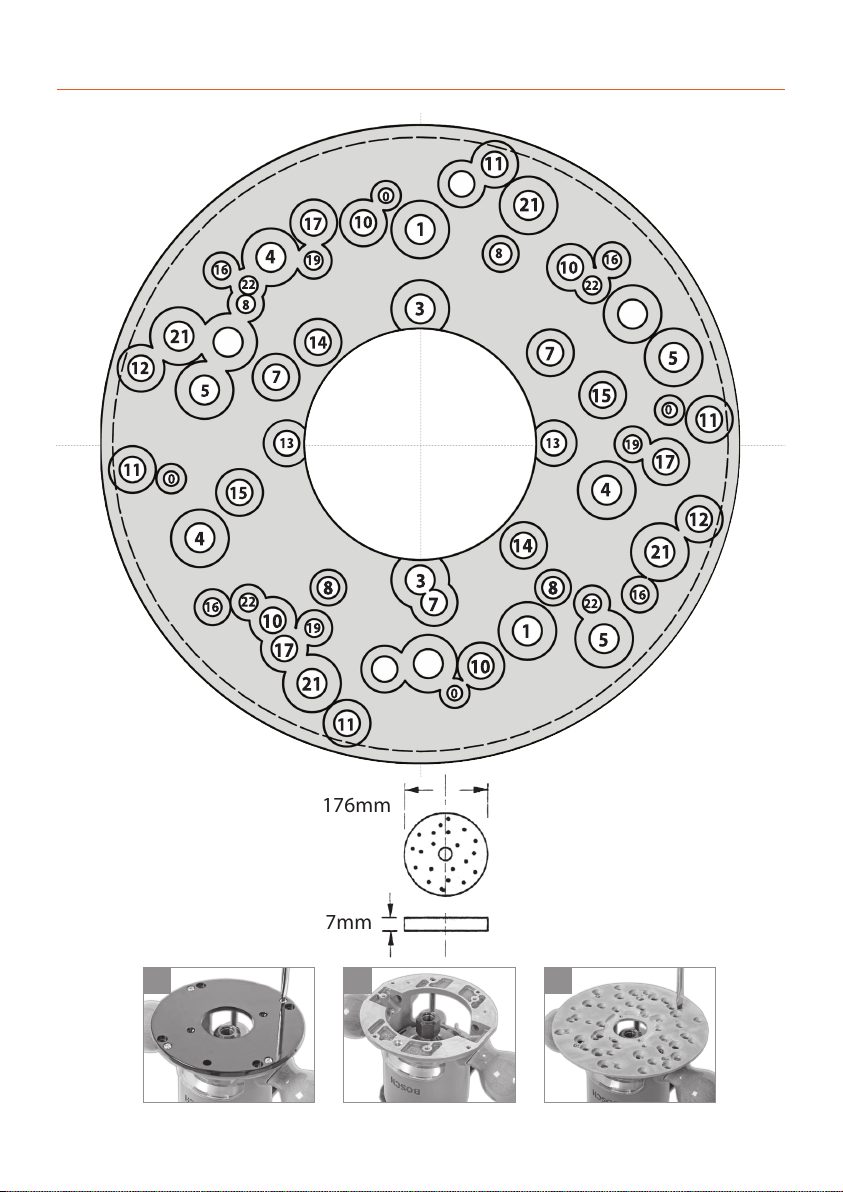
Fitting the Router and the Cutters
10
Fig 1
Fig 2
Fig 3
IN ORDER TO FIT SOME OF THE ROUTERS TO THE ELEVATOR AND ACHIEVE
UNRESTRICTED MOVEMENT, IT MAY BE NECESSARY TO REMOVE THE HANDLES;
PLUNGE THE ROUTER BODY TO DEPTH, ETC., ETC.
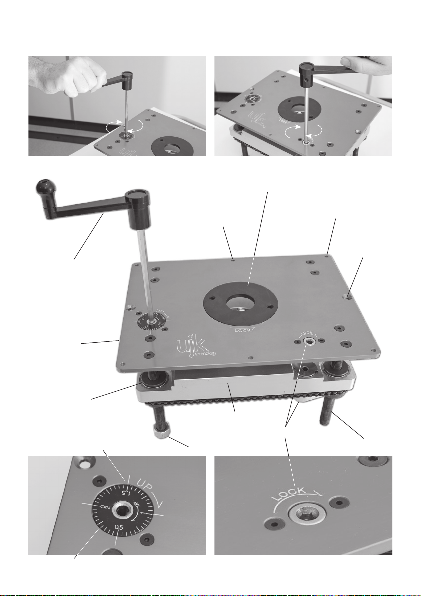
Lower the table to almost its fullest extent. Using the
Allen key provided loosen the bolts and therefore the lugs
holding the universal mounting plate (UMP) in position
and remove. (See Figs 1 and 2).Remove the sole plate from
your router, see illustrations 1 to 2 and secure your router
to the UMP via the appropriate holes, see pages 8-9. Insert
the requisite tool into the router and tighten securely.
Adjust the‘depth’of the router to give the slightly more
than the required exposure of the tool (to allow for
adjustment) and lock the body. Remember that you will
loose 14.5mm of the set ‘height’ of the cutter between the
lower face of the universal mounting plate and the upper
surface of the machine table. Alternatively, current practise
would indicate that the router is plunged to maximum
depth and all height adjustment is done using the elevator.
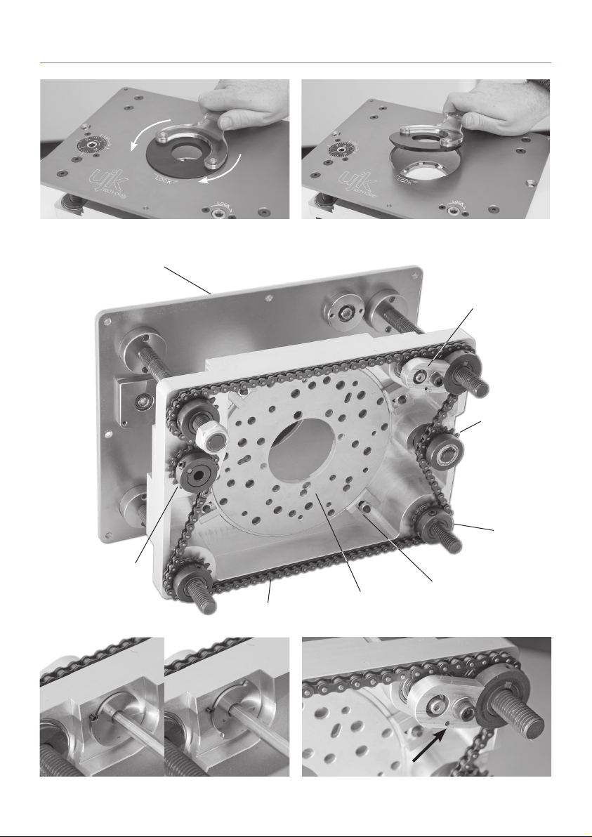
Refit the mounting plate to the rise and fall platform.(See
Fig 3)
Re-fasten the holding lugs. If the router tool diameter is
greater than 75mm, the router/mounting plate combina-
tion must be refitted to the rise and fall platform first, and
then the tooling mounted into the router. (Hint.You will
find this easier with the rise and fall platform at its highest
position and the table insert removed).
Mounting plate holding down lug
Router/mounting plate mounted in the router elevator
Please note: Removing the router handles will
prevent them from interfering with the chain.
1
2
UMP (universal mounting plate)
Sole plate