Azkoyen VITRO S-1 User manual

USER MANUAL
COFFEE MACHINE VITRO “S-1”
MANUAL REFERENCIA: 81044 307; EDICIÓN 01-20 9
1

User Manual VITRO S1
- 2 -
AZKOYEN S.A. Azkoyen Andina S.A.S.
Av. San Silvestre S/N Vía Virginia
31350 PERALTA Corregimiento Caimalito, Bodega B-16
Navarra, ESPAÑA Zona Franca Internacional
660007 – Pereira, COLOMBIA

User Manual VITRO S1
- 3 -
WARNINGS ............................................................................................................................... 4
UE Declaration of Conformity ................................................................................................. 6
CHAPTER 1. GENERAL CHARACTERISTICS ........................................................................ 7
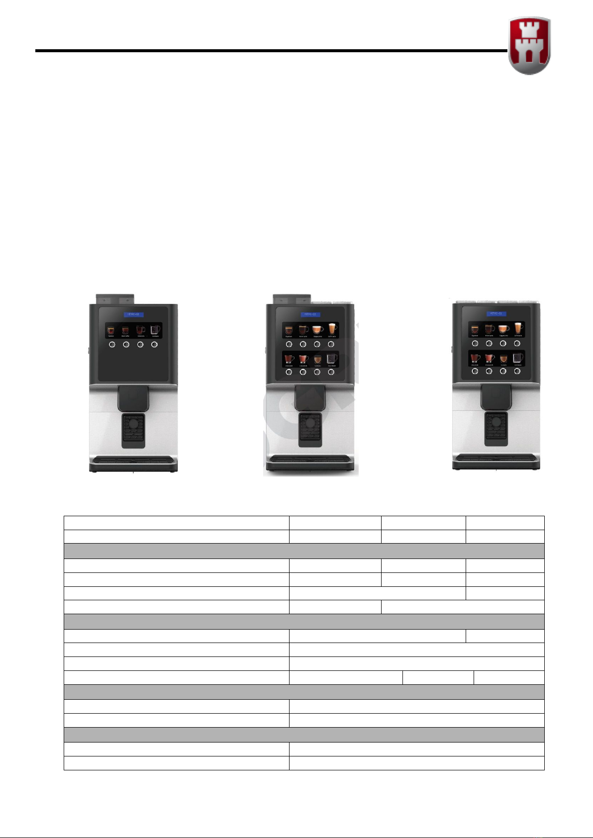
1.1.- Description of the machine. ........................................................................................... 7
1.2.- Description of the main components .............................................................................. 8
CHAPTER 2. INSTALLATION AND STARTING-UP ................................................................ 9
2.1.- Choice of location for the machine ................................................................................. 9
2.2.- Electrical installation ...................................................................................................... 9
2.3.- Start-up .......................................................................................................................... 9
2.4.- Water supply .................................................................................................................. 9
2.5.- Payment module .......................................................................................................... 10
CHAPTER 3. DESCRIPTION OF THE MACHINE .................................................................. 11
3.1.- Soluble product hoppers .............................................................................................. 11
3.2.- Initial loading of soluble product. .................................................................................. 11
3.3.- Loading coffee beans ................................................................................................... 11
3.4.- Initial loading of water .................................................................................................. 11
3.5.- Programming the water temperature under special conditions .................................... 12
3.6.- Bean coffee group (Espresso Machines) ..................................................................... 12
3.7.- Dismantling the coffee bean group .............................................................................. 13
3.8.- Settings and adjustments ............................................................................................. 13
CHAPTER 4. PROGRAMMING .............................................................................................. 15
4.1.- How do we communicate with the machine? ............................................................... 15
4.2.- What can be programmed? ......................................................................................... 15
4.3.- Programming menu .................................................................................................... 15
4.4.- List of functions ............................................................................................................ 16
4.5.- Customising the Programming Menu ........................................................................... 18
4.6.- Service programming. .................................................................................................. 18
CHAPTER 5 – TROUBLESHOOTING AND MAINTENANCE ................................................ 21
5.1 - Reset ........................................................................................................................... 21
5.2.- Error detected by the machine. .................................................................................... 21
5.3.- Changing the product labels ........................................................................................ 22
CHAPTER 6. CLEANING THE MACHINE. ............................................................................ 23
6.1.- Components that require regular cleaning ................................................................... 23
6.2.- Regular cleaning of the machine and maintenance operations ................................... 24
6.3.- Cleaning cycle for the group brewing chamber ............................................................ 24
6.4.- Descaling cycle. ........................................................................................................... 26
6.5.- Replacing the water filter ............................................................................................. 27
6.6.- Exterior cleaning .......................................................................................................... 27
Anexe 1. THE TREATMENT, COLLECTION, RECYCLING AND DISPOSAL OF THIS
DEVICE ................................................................................................................................... 28

User Manual VITRO S1
- 4 -
WARNINGS
General
BEFORE USING THIS DISPENSER, THIS MANUAL MUST BE READ CAREFULLY
This automatic dispenser has been designed and built in accordance with all safety legislation in
force.
Installation
THE INSTALLATION AND OPERATIONS REQUIRED FOR INITIAL START-UP OF THESE MACHINES
MUST BE PERFORMED BY QUALIFIED PERSONNEL.
The plug of the machine has an earth connection. The outlet must be connected to a good earth
connection and must be located in an accessible position once the machine is installed.
Ensure that the electrical installation, the outlet and the automatic circuit breaker have the
appropriate sizes for machine consumption.
These machines are designed EXCLUSIVELY FOR INDOOR USE. They must not be installed in
places that may be exposed to sprayed water, and they likewise must not be cleaned using
sprayed water.
Safety
The machine should be installed in locations that meet the recommendations of temperature,
electrical and water installations, weights, etc., in this manual and performed by qualified
personnel.
THE MACHINE HAS COMPONENTS THAT OPERATE AT DANGEROUS VOLTAGES. DO NOT
DISCONNECT ANY COMPONENT. ONLY TECHNICAL SERVICE IS AUTHORISED. THE FEEDER
CABLE CAN ONLY BE REPLACED BY AUTHORISED TECHNICAL PERSONNEL.
This appliance is not designed to be used by persons (including children) with reduced physical,
sensory or mental capabilities, lack of experience or knowledge, unless they are supervised or
have been instructed in its use by somebody responsible for their safety. Children should be
supervised to ensure that they do not play with the appliance. Section 7.12 of EN60335.
This appliance is not designed to be used by persons (including children aged 8 and above) with
reduced physical, sensory or mental capabilities, lack of experience or knowledge, unless they
are supervised or have been instructed in its use by somebody responsible for their safety.
In any case, this appliance cannot be cleaned and serviced by unsupervised children.
AZKOYEN hereby declines all liability for damages caused to persons or things as a result of the
following:
o Incorrect installation.
o Inadequate electrical and/or hydraulic installation.
o Deficient cleaning or maintenance.
o Incorrect use of the machine.
o Using non-original replacement parts or making unauthorised modifications

User Manual VITRO S1
- 5 -
If it is necessary to move the machine avoid:
o Tipping the machine
o Dragging or lifting it with some kind of pulling system (rope, straps, etc.).
o Shaking or striking the machine, no matter whether it is in protective wrapping or not.
All elements that require tools to be disassembled must only be handled by qualified technical
personnel.
Mantenaince
Given the characteristics of some food products, these may lead to incorrect operation of the
machine if used beyond the parameters of temperature and relative humidity recommended in
this manual.
Water must be prevented from freezing in the interior of the machine. If any maintenance task
is going to performed and the machine is going to be disconnected for a long period of time, the
boiler must be emptied.
The user or person responsible for refilling and cleaning the device must follow the instructions
set forth in this manual.
For refilling, only use food products prepared specifically for these kinds of vending machines. Do
not touch the product with your hands, and prevent liquids from falling inside the product
hoppers.
User manual
This manual is an integral part of the machine, and as such, it must always remain inside the same
so that it may be consulted at any time.
This document contains private property information protected by legislation on intellectual
property. All rights are hereby reserved. No part of this document may be photocopied,
reproduced or translated without the prior written consent of AZKOYEN.
AZKOYEN hereby reserves the right to introduce, without prior notice, all improvements to this
model derived from its constant research.
REMEMBER: To get the most out of your machine, follow the instructions in this manual.
FOR ANY ADDITIONAL INFORMATION THAT IS NOT SPECIFIED HEREIN CONTACT YOUR
DISTRIBUTOR OR ACCESS THE
TECHNICAL MANUAL FROM AZKOYEN'S OFFICIAL WEBPAGE

User Manual VITRO S1
- 6 -
UE Declaration of Conformity
We, the manufacturer, Azkoyen Vending Systems, declare under our sole responsibility that our product
is in compliance with the essential requirements of the following European Union issued Directives:
EMC Directive 2014/30/UE, and his modifications
Low Voltage Directive 2014/35/UE, and his modifications
RoHS Directive 2015/863/UE
Regulation 1935/2004, on materials and articles intended to come into contact with food
The product is according with the following norms / standards:
UNE-EN 60335-2-75:05 +A1:2005+A11:2006 + A2:2008+A12:2010
UNE-EN 60335-1:2012+AC: 2014+A11:2014
UNE-EN 55014-1:08 + A1:09+A2:2012
UNE-EN 55014-2:2015
UNE-EN 61000-3-2:2014
UNE-EN 61000-3-3:2013
Azkoyen Vending Systems
Avda. San Silvestre, s/n
31350 – peralta. SPAIN

User Manual VITRO S1
- 7 -
CHAPTER 1. GENERAL CHARACTERISTICS
1.1.- Description of the machine.
The machines on the VITRO S1 range are TABLETOP coffee and soluble beverage machines especially
designed for use in areas with medium coffee consumption, such as waiting rooms, medium-sized
offices, etc.
There are three machine configuration options:
Instant, only with soluble products
Espresso + 2, with two soluble product containers and coffee-bean system.
Espresso, fitted with a system to make espresso coffee from coffee beans
Espresso Espresso+ 2 Instant
Espresso Espresso+2 Instant
No. of selections 4 8 8
Product
No. bean containers 1 1 0
No. soluble product containers 0 2 4
Bean container capacity (l.) 3,1 l -
Soluble product container capacity (l) - 1,6 l
Dimensions
Height 635 605
Width 305
Depth 415
Weight (kg) 19,7 26.2 24.3
Electrical characteristics
Voltage according to the characteristics plate (+6V/-10V)
Maximum Power consumption (W) < 1500W
Water supply
Types of supply Mains or incorporated tank
Minimum input pressure min 0,049 Mpa.; Max. 0,98 Mpa

User Manual VITRO S1
- 8 -
Diameter of the stopcock (to connect the
mains hose)
¾” M
Water tank capacity (l) 4
Other Characteristics
Maximum work gradient 2º (on any axis)
Sound level <80 dB(A)
Optimum exterior environment temperature > 1ºC - <40ºC; <65% Rel. hum.
1.2.- Description of the main components
Fig. 1
1. Coffee bean container
2. Soluble product container
3. Ground coffee doser
4. Soluble product blender
5. Coffee bean group
6. Rubber threshold
7. Drip tray
8. Programming button (“PROG”)
9. Display
10. Selection buttons
11. Cup holder
12. Suction tube
13. Tray full level
14. Water tank
1
2
3
4
5
6
7
8
9
10
11
12
14
13

User Manual VITRO S1
- 9 -
CHAPTER 2. INSTALLATION AND STARTING-UP
2.1.- Choice of location for the machine
The machine must be placed on a unit or support so that it is stable and cannot be accidentally knocked
over. The support must be well secured to the wall.
THE INSTALLATION OPERATIONS REQUIRED FOR THE INITIAL START-UP OF THESE
MACHINES MUST BE PERFORMED BY QUALIFIED TECHNICAL STAFF.
2.2.- Electrical installation
The voltage of the electrical system must comply with the voltage indicated on the characteristics plate
on the back of the machine and must not exceed the limits set in the country of use.
Maximum power consumption is indicated on the machine characteristics plate.
2.3.- Start-up
Once the tank has been filled or the water hose has been
connected to the mains and current fed to the socket, close
the door: The machine will be ready for use in a few minutes.
Press the switch on the back of the machine.
2.4.- Water supply
If your machine is fitted with mains service, then prepare a
water supply where the machine is to be fitted in accordance with the indications in the general
characteristics table. The distance between this water supply and any electric socket base must be at
least 1 m. Observe European directives.
If your machine is fitted with a water tank, remove it from the side of the machine for filling.
WHEN CONNECTING THE MACHINE STARTS FILLING THE WATER CIRCUIT. DO NOT
REMOVE THE CONTAINER UNTIL THE OPERATION IS COMPLETE.

User Manual VITRO S1
- 10 -
2.5.- Payment module
The machine can feature an optional payment module, which supports connection of a validator with
MDB protocol. The installation instructions are included in the corresponding kit.
THE MACHINE CAN ONLY BE POWERED WITH 24DC (NOT WITH 24VAC).

User Manual VITRO S1
- 11 -
CHAPTER 3. DESCRIPTION OF THE MACHINE
3.1.- Soluble product hoppers
The Instant and Espresso+2 machines have 2 or more soluble product containers.
These containers extract the product via a spindle to the Blender, where it is mixed with water sent from
the boiler.
Each hopper must always be loaded with the same type of product because the serving configuration
activates the hopper programmed for each case.
e.g. do not load the coffee hopper with a different product because the machine will use it for servings
programmed with coffee.
3.2.- Initial loading of soluble product.
Lift the lid of the hopper to be loaded and load the product. Make sure
that the product loaded is the right product for the hopper (each hopper
has a label indicating the product to load).
When the product has been loaded, close the lid and proceed to load
the next hopper.
3.3.- Loading coffee
beans
Lift the hopper lid and pour in the contents of the packet of coffee
to the desired level.
3.4.- Initial loading of water
All the machines automatically fill the boiler when the machine is started up.
BEFORE CONNECTING THE MACHINE, MAKE SURE THAT THERE IS
WATER AVAILABLE TO FILL THE BOILER (check the mains hose
connection or make sure that the water tank is full)

User Manual VITRO S1
- 12 -
3.5.- Programming the water temperature under special conditions
The machine is programmed at the factory with an 85ºC boiler temperature by default. The water boiling
point can be much less than 100ºC in some cities, according to their altitude. Malfunction of the hydraulic
system of the unit can be caused if the temperature of the machine is modified to higher water boiling
temperatures. Examples:
Altitude
(over sea level)
Temp. Water boiling Temp. Max. recommended of
the boiler (Function 461)
1500m
95ºC
92ºC
1800m
94ºC
91ºC
2100m
93ºC
90ºC
2400m
92ºC
89ºC
2700m
91ºC
88ºC
3.6.- Bean coffee group (Espresso Machines)
The coffee beans are stored in the grinder hopper. When a serving is requested, the brewing group
moves to the loading position and the grinder grinds the amount of coffee programmed, sending it to
the doser, where the coffee is dosed and then falls to the brewing piston.
The group then advances to the brewing position and the piston tamps the coffee.
The pump injects the programmed water into the group for the pre-set length of time. The result of this
operation is the Espresso coffee which pours into the cup.
Fig. 2
1 Hopper
2 Doser
3 Upper piston
4 Lower group
5 Group anchoring lever
6 Grinder adjustment lever
7 Coffee outlet tube
8 Group positioning crank
1
2
3
4
5
6
7
8

User Manual VITRO S1
- 13 -
3.7.- Dismantling the coffee bean group
To extract the brewing piston,
1. Set the group to stand-by position by entering
programming and pressing button 6 (see
programming).
2. Remove the securing pin.
3. Pull the piston upwards.
4. If you wish to dismantle the piston
completely, remove the securing clip.
If you wish to dismantle the entire lower group, dismantle the
group water input hose and then turn the group securing levers
and extract the group by pulling it out.
3.8.- Settings and adjustments
Adjusting the coffee dose in espresso machines WITH a dosing system. The brewing piston on the group
has a washer with which it is possible to increase or decrease the capacity of the brewing cylinder and
thereby adjust the amount of ground coffee it can contain. The quantity can vary between 5g and 8g.
The doser also needs to be adjusted so as to send the right amount to the cylinder.
The following diagram indicates the position of the washer and the doser lever to set the desired
amount.
The dose is factory set to 6.5 g of ground coffee (100 % natural coffee)

User Manual VITRO S1
- 14 -
Adjusting the coffee dose in espresso machines WITHOUT a dosing system. The grinder must be
calibrated in machines without a dosing system using function F030.
After it has been calibrated, the grinder will adjust the coffee dose after each service, as programmed
with function 315.
For example: every 2.45 seconds of operation of the grinder will produce an amount equivalent to 7 g.
IMPORTANT: The washer position must be adjusted as indicated in the above diagram. If not, the unit
might malfunction and faults might even be caused.
Calibrating the grinder.
1 Remove the coffee grinder unit, as described in point 3.7.
2 Access the programming menu (see Chap. 4) and select function F030. Press the A and B
buttons until the display shows “GRINDER”. Next, press the D button.
3 The machine will grind and extract coffee during 10 seconds. Place a container at the grinder
outlet to collect the ground coffee.
4 Weigh the extracted product and enter the value using buttons A and B. Validate using button
D.
The machine will now indicate the weight of the product in grams.
Coffee grinding point adjustment. The grinder leaves the factory set to the optimum grinding position.
If you want to grind the coffee finer, then you can move the adjustment lever one or two positions (with
the motor running to prevent the teeth from jamming with coffee).
The grinder adjustment lever is at the top of the group. Use it to set the ground coffee grade you wish
to use.
A “good coffee” is one which has been brewed at 9 kg/cm2, which is equivalent to a brewing time of
between 15 and 20 sec.

User Manual VITRO S1
- 15 -
CHAPTER 4. PROGRAMMING
4.1.- How do we communicate with the machine?
VITRO S1 machine uses a selection keypad to communicate with the machine user.
When the machine is in programming status, the programmable functions are accessed by pressing the
different buttons.
The machine has an information screen which shows messages during service, programming and
warning messages for maintenance and cleaning.
4.2.- What can be programmed?
To access the programming screen, press the “PROG”
button on the inside of the door (Fig. 1).
The PROG button can also be used to exit the programming
mode.
4.3.- Programming menu
Vitro S1 units will be programmed from the display of the machine.
Press the selection buttons on the top row of the panel to programme the machine, edit its values, etc.
(the espresso machine only has one row).
The buttons behave as follows in the programming mode:
Button A Function goes forward
Button B Function goes backward
Button C Exits the programming
Button D Accesses the function that is displayed at that moment or executes the function
automatically (EXE mode)
Button E Free Sale (1 service)
Button F Mixer washing
Button G Boiler water temperature
Button H Not used
A B C D
E F G H
PROG

User Manual VITRO S1
- 16 -
Some buttons will have different functions and perform different actions:
Alfanumerical (AB1)
Button A The digit being edited goes up one character in the table.
Button B The digit being edited goes down one character in the table.
Button C Erase the digit being edited, and it returns to editing the previous digit.
Button D The character is validated, and it goes to editing the next digit.
PROG Stops the editing process, saving the information on the display
Numerical (001)
Button A Increases the digit being edited (if it is a sign, it changes)
Button B Decreases the digit being edited (if it is a sign, it changes)
Button C It returns to editing the previous digit (if it is the first number, it edits the sign,
and if it is the sign, it exits and validates)
Button D It advances to editing the next digit (if it is the first number, it edits the sign, and
if it is the sign, it exits and validates)
PROG Stops the editing process, saving the information on the display
Options List (ABC)
Button A The next option on the list is accessed (if it is the last option, it goes to the first).
Button B The previous option on the list is accessed (if it is the first option, it goes to the
last)
Button C It goes up one execution level
Button D Validates the value shown on the display and exits the function
4.4.- List of functions
The full list of functions of the machine and their edit mode are shown below.
Función Descripción Modo Edición
F010 LISTING
ABC
F030 MACHINE TEST
ABC
F090 SW.VERSIONS ABC
F091 INITIALISATION EXE
F110 SALES BY SELECTION (CASH)
EXE
F111 SALES BY SELECTION (UNITS)
EXE
F113 SALES PER SELECTION UNDER FREE SALE
EXE
F120 TOTAL AMOUNT OF SALES
EXE
F121 TOTAL UNITS SOLD
EXE

User Manual VITRO S1
- 17 -
Función Descripción Modo Edición
F122 TOTAL SALES UNDER FREE SALE
EXE
F141 CASH IN COIN BIN
EXE
F142 CASH IN THE RETURNER TUBES
EXE
F145 CASH DISPENSED MANUALLY
EXE
F146 VALUE OF CHANGE NOT GIVEN
EXE
F147 MONEY IN CREDIT WITHDRAWN FROM PREPAID CARDS
EXE
F148 CASH COLLECTED FOR PREPAID CARD RECHARGES.
EXE
F149 CASH IN BILLS
EXE
F171 DELETES ACCOUNTED
EXE
F180 PERPETUAL ACCOUNTING OF TOTAL SALES
EXE
F191 PERPETUAL ACCOUNTING OF SALES, BY SELECTION (UNITS)
EXE
F201 PRICES WITH COINS
001
F204 SINGLE PRICE FOR ALL SELECTIONS
001
F220 FREE SALE
ABC
F221 MULTIVEND
EXE
F300 SELECTION-SERVICE ASSOCIATION
AB1
F315 PROP SERVICE PROGRAMMING
Ver 4.6
F317 PROP PRE-SELECTION PROGRAMMING
F401 MACHINE TYPE
ABC
F412 INPUT COINS (BLOCKING/VALUE)
ABC
F416 MAXIMUM ALLOWED PER TYPE OF COIN
001
F418 COIN ADMISSION OUT OF CHANGE
001
F419 OUT OF CHANGE CALCULATION FUNCTION
ABC
F420 ADVERTISING MESSAGE
AB1
F421 SPECIAL EFFECT MESSAGE
AB1
F424 OUT-OF-SERVICE MESSAGE
AB1
F430 LANGUAGE
AB1
F431 NAME OF THE MONETARY UNIT
AB1
F432 NUMBER OF DECIMALS
001
F454 CARD READER
ABC
F455 BILL READER
ABC
F461 BOILER TEMPERATURE
ABC
F463 AUTOMATIC WASH
001
F465 STAND ALONE UNIT YES/NO
ABC+001
F472 OPERATOR CODE (4 DIGITS)
ABC
F490 NAME OF THE HOPPERS
AB1
F491 NAME OF THE SERVICES
AB1
Remember that you can only use the functions shown in the Programming Menu

User Manual VITRO S1
- 18 -
4.5.- Customising the Programming Menu
The machine has many different internal programming functions. However, you can only use the
functions shown in the Programming Menu and those displayed when the programming screen is
displayed.
The Programming Menu can be customised. You can add or delete the functions of this menu to
customise it.
To customise the menu:
Hold down the PROG button for 5 sec. The full list of functions of the machine will be displayed. You can
browse the list of functions with the A and B buttons.
The screen will show whether the function is included in the programming menu or not, adding a “P”
between the function number and its text box.
Or “– “ if it is not included
Press the D button to change the value of this digit.
Press the A or B button to save and edit a different function.
Press C to save the value and exit the programming menu.
4.6.- Service programming.
4.4.1.- What is a service?
A service is the act that the machine performs every time that a customer presses a selection. More
specifically, a service is the steps that the machine must take in order to complete the operation that
has been selected.
Therefore, when programming a service, each one of these steps must be programmed. For example: At
home, when you prepare a soluble coffee with milk, various actions must be taken:
1) Put coffee in a cup.
2) Add sugar.
3) Add hot water.
4) Stir the mixture.
5) Add milk.
It is also a good idea for the actions to overlap each other in order to shorten the service time and to get
the optimum mixture.
010 P LISTADOS
010 – LISTADOS

User Manual VITRO S1
- 19 -
The service sequence of coffee with milk in the machine could thus be stated as follows:
Step 1
Step 2
Step 3
Step 4
Step 5
4.6.2.- Function 315 PROG. SERVICE.
The complete configuration of each service can be programmed at function 315.
Within this configuration, you can program the various steps that the machine must perform in order to
provide that service, the time that it starts during the service and the duration.
Once function 315 is accessed, choose the service to program, pushing the corresponding selection
button.
The following may subsequently be performed:
MODIFY an already-programmed step.
ADD a new step to a service, or
DELETE a step from a service.
Pass from one step of the service to another by pressing buttons A and B (up/down respectively) and
then button C to select the step displayed on the screen.
If the option, MODIFY A STEP, is selected, the machine will display the CONFIGURATION SCREEN of the
step:
HOPPER ACTION
ST: 00.0 ET: 00.0
Where:
HOPPER is the name of the hopper that is going to used.
ACTION is the type of operation that is going to be performed with that hopper (add water,
product...).
ST The start time of the action, which starts counting as from the moment the machine is in
the service position. Two whole numbers and one decimal can be entered (between 0.0
and 25.59.
ET Tiempo de producto o volumen.
If WATER is being programmed, the volume in c.c., en máquinas con contador
volumétrico, that is going to be dispensed in that step should be programmed instead of
the end time.

User Manual VITRO S1
- 20 -
After choosing the step to edit, start editing. The field to be edited flashes (it can be the field of the name
of the hopper, the type of step or one of the digits in the time or volume values).
Button D only works when editing the 2nd digit or higher. Finish by pressing PROG.
In each step, the start time, the action to be performed and what hopper or blender is going to perform
the action and its time in seconds must all be programmed.
After finishing the programming of each step, the screen will display the programming and then the next
step can be programmed.
If ADD A STEP has been selected, direct access to the new step will be provided. The procedure
is the same as the aforementioned one.
If DELETE A STEP is selected, select the step (pressing 1 or 2) and then delete it (pressing 3).
NOTE: If P is pressed at any time during the programming of a step, programming will be exited and the
data will not be recorded
Other manuals for VITRO S-1
2
Table of contents
Other Azkoyen Coffee Maker manuals

Azkoyen
Azkoyen ZEN Manual

Azkoyen
Azkoyen VITRO S-1 Owner's manual

Azkoyen
Azkoyen VITALE S User manual

Azkoyen
Azkoyen VITALE S Owner's manual

Azkoyen
Azkoyen VITALE S Manual

Azkoyen
Azkoyen AZKOY GROUP VITRO S5 User manual

Azkoyen
Azkoyen BRAVO Automatic 2G Manual

Azkoyen
Azkoyen VITRO S-1 Manual

Azkoyen
Azkoyen VITRO M5 User manual

Azkoyen
Azkoyen Vitro S1 MIA Operating instructions