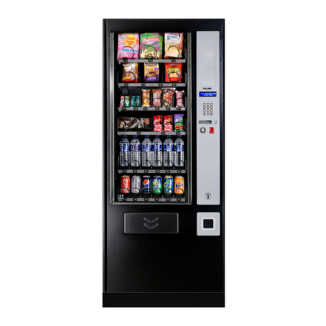
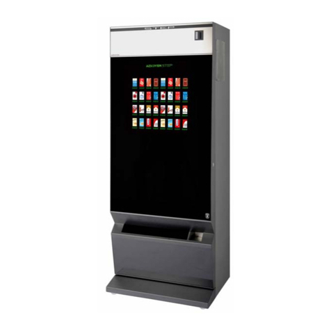
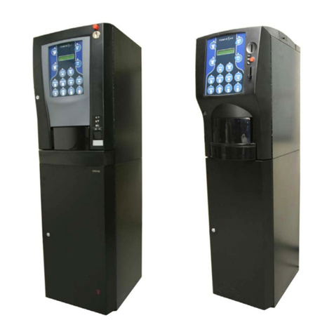
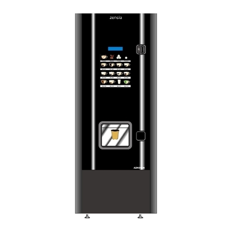
Azkoyen Zensia User manual

User’s Manual
Hot Drink Vending Machines
«Zensia»
MANUAL REFERENCIA: 81039340; EDICIÓN 09/2017

User Manual ZENSIA
- 2 -

User Manual ZENSIA
- 3 -
INDEX
CAUTIONS................................................................................................................................................................ 4
CHAPTER 1. GENERAL CHARACTERISTICS....................................................................................................... 7
1.1.-
D
ESCRIPTION OF THE
NOVARA
LINE
............................................................................................................... 7
1.2.-
M
AIN CHARACTERISTICS
................................................................................................................................... 7
1.3.-
D
ESCRIPTION OF THE MAIN COMPONENTS
......................................................................................................... 9
CHAPTER 2. INSTALLATION AND STARTING UP ............................................................................................. 13
2.1.-
E
LECTRICAL
I
NSTALLATION
............................................................................................................................. 13
2.2.-
W
ATER INLET
................................................................................................................................................ 13
2.3.-
L
EVELLING
.................................................................................................................................................... 13
2.4.-
S
TARTING UP
................................................................................................................................................. 13
2.5.-
I
NSTALLATION OF THE PAYMENT SYSTEMS
....................................................................................................... 13
2.6.-
C
HANGING THE PRODUCT AND PRICE SIGN
................................................................................................... 14
2.7.
I
NSTALLATION OF OPTIONAL KITS AT THE BASE OF THE MACHINE
........................................................................ 14
2.8.
-
L
OAD LEVEL LABELS OF THE HOPPERS
........................................................................................................... 14
CHAPTER 3. FILLING THE MACHINE.................................................................................................................. 15
3.1.-
I
NITIAL FILLING WITH SOLUBLE PRODUCT
......................................................................................................... 15
3.2.-
F
ILLING WITH COFFEE BEANS
.......................................................................................................................... 15
3.3.-
F
ILLING WITH CUPS
........................................................................................................................................ 16
3.4.-
F
ITTING THE HYGIENE PARTS
.......................................................................................................................... 17
3.5.-
F
ILLING THE RETURNER TUBES
....................................................................................................................... 17
3.6.-
I
NITIAL FILLING WITH WATER
........................................................................................................................... 17
3.7.-
I
NITIAL PROGRAMMING
................................................................................................................................... 18
CHAPTER 4. CONFIGURATION AND PROGRAMMING...................................................................................... 19
4.1.-
W
HAT IS PROGRAMMING
? .............................................................................................................................. 19
4.2.-
P
ROGRAMMING CONTROL UNIT
....................................................................................................................... 19
4.3.-
D
IRECT ACCESS TO A FUNCTION
..................................................................................................................... 20
4.4.-
L
IST OF FUNCTIONS
........................................................................................................................................ 20
4.5.-
S
ERVICE PROGRAMMING
................................................................................................................................ 22
CHAPTER 5. ANOMALY CONTROL AND MAINTENANCE................................................................................. 25
5.1.-
R
ESET
.......................................................................................................................................................... 25
5.2.-
P
OSSIBLE INCIDENTS DURING A SERVICE
......................................................................................................... 25
5.3.-
S
ERVICE
M
ETERS
.......................................................................................................................................... 25
5.4.-
D
ISASSEMBLY OF THE COFFEE BEAN UNIT
....................................................................................................... 25
5.4.2.-
A
DJUSTMENTS AND REGULATION
................................................................................................................. 26
CHAPTER 6. CLEANING THE MACHINE. ........................................................................................................... 29
6.1.-
C
OMPONENTS THAT REQUIRE REGULAR CLEANING
.......................................................................................... 30
6.2.-
C
LEANING OF THE SUGAR CHUTE
(
ESPRESSO MACHINES
)................................................................................. 31
6.3
-
C
LEAN THE SERVICE COMPARTMENT
............................................................................................................... 31
6.4.-
C
LEANING CYCLE FOR THE GROUP BREWING CHAMBER
................................................................................... 31
6.4.-
C
LEANING THE TEA BREWER
(
ON MACHINES THAT INCORPORATE IT
)................................................................. 32
6.5.-
R
EFITTING THE TEA BREWER
.......................................................................................................................... 33
6.6.-
F
ILTER BELT REMOVAL AND REPLACEMENT
...................................................................................................... 33
6.5.-
D
ETECTION OF WASTE LEVEL
.......................................................................................................................... 34
6.6.-
E
XTERIOR CLEANING
...................................................................................................................................... 34
6.7.-
C
LEANING THE PAYOUT UNIT
.......................................................................................................................... 34


User Manual ZENSIA
- 4 -
CAUTIONS
General
BEFORE USING THIS DISPENSER, THIS MANUAL MUST BE READ CAREFULLY. This manual is an
integral part of the machine, and as such, it must always remain inside the same so that it may be
consulted at any time.
This automatic dispenser has been designed and built in accordance with all safety legislation in force.
AZKOYEN hereby guarantees that these machines comply with the following directives:
CE Low Voltage Directive DBT 73/23/CEE and its amendments
CE Electromagnetic Compatibility Directive EMC 89/336/CEE and its amendments
CE Machinery Directive 2006/42/EC and its amendments
This document contains private property information protected by legislation on intellectual property. All
rights are hereby reserved. No part of this document may be photocopied, reproduced or translated
without the prior written consent of AZKOYEN.
AZKOYEN hereby declines all liability for damages caused to persons or things as a result of the
following:
oIncorrect installation.
oInadequate electrical and/or hydraulic installation.
oDeficient cleaning or maintenance.
oIncorrect use of the machine.
oUsing non-original replacement parts or making unauthorised modifications
AZKOYEN hereby reserves the right to introduce, without prior notice, all improvements to this model
derived from its constant research.
This appliance is not designed to be used by persons (including children) with reduced physical, sensory
or mental capabilities, lack of experience or knowledge, unless they are supervised or have been
instructed in its use by somebody responsible for their safety. Children should be supervised to ensure
that they do not play with the appliance. Section 7.12 of EN60335.
Given the characteristics of some food products, these may lead to incorrect operation of the machine if
used beyond the parameters of temperature and relative humidity recommended in this manual.
If it is necessary to move the machine avoid:
oTipping the machine
oDragging or lifting it with some kind of pulling system (rope, straps, etc.).
oShaking or striking the machine, no matter whether it is in protective wrapping or not.
Installation
These machines are designed EXCLUSIVELY FOR INDOOR USE. They must not be installed in places
that may be exposed to sprayed water, and they likewise must not be cleaned using sprayed water.
The machine should be installed in locations that meet the recommendations of temperature, electrical
and water installations, weights, etc., in this manual and performed by qualified personnel.
The plug of the machine has an earth connection. The outlet must be connected to a good earth
connection and must be located in an accessible position once the machine is installed.
THE INSTALLATION AND OPERATIONS REQUIRED FOR INITIAL START-UP OF THESE
MACHINES MUST BE PERFORMED BY QUALIFIED PERSONNEL.
Mantenaice
The user or person responsible for refilling and cleaning the device must follow the instructions set forth in
this manual.
For refilling, only use food products prepared specifically for these kinds of vending machines. Do not
touch the product with your hands, and prevent liquids from falling inside the product hoppers.

User Manual ZENSIA
- 5 -
All elements that require tools to be disassembled must only be handled by qualified technical personnel.
Water must be prevented from freezing in the interior of the machine. If any maintenance task is going to
performed and the machine is going to be disconnected for a long period of time, the boiler must be
emptied.
Electrical
THE MACHINE HAS COMPONENTS THAT OPERATE AT DANGEROUS VOLTAGES. DO NOT
DISCONNECT ANY COMPONENT. ONLY TECHNICAL SERVICE IS AUTHORISED
Ensure that the electrical installation, the outlet and the automatic circuit breaker have the appropriate
sizes for machine consumption.
Symbols used on the machine
This symbol on a label indicates if you need more information, you can be found in the User
Manual.
FOR ANY ADDITIONAL INFORMATION THAT IS NOT SPECIFIED HEREIN CONTACT
YOUR DISTRIBUTOR OR ACCESS THE TECHNICAL MANUAL FROM AZKOYEN'S
OFFICIAL WEBPAGE

User Manual ZENSIA
- 6 -

User Manual ZENSIA
- 7 -
Hot Drink Vending Machines
ZENSIA
Instant
&
Espresso
CHAPTER 1. GENERAL CHARACTERISTICS
1.1.- Description of the NOVARA line
The AZKOYEN ZENSIA range of machines are coffee and instant drinks dispensers which
have been specially designed for use in medium-to-high consumption areas such as waiting
rooms, offices, factories, etc...
All the machines can be the INSTANT versions that only use soluble products, or the
ESPRESSO versions, which are equipped with a brewer for preparing espresso coffee using
coffee beans.
Configurations of the ZENSIA range (plan view)
Instant Espresso Instant+Fresh brew
1.2.- Main characteristics
Dimensions (mm)
Depth 660
Height 1830
Width 600
Weight (kg) – Instant/Espresso 165/180
Technical specifications
Voltage See characteristics plate (+6%/-10%)
Maximum impedance (at the connec. point) Zmax = 0,28Ω
Maximum consumption Instant -> 2.300 W
Espresso -> 1100 – 1500

User Manual ZENSIA
- 8 -
Characteristics of the water supply system
Types of water service connections Water supply system, stand-alone
on stand or with an incorporated
tank.
Min. pressure of the water supply system min. 0,098 Mpa.; Max. 0,98 Mpa
Curb cock diameter ¾” M
Boiler capacity 2,8 l. (Instant) / 0,7 l. (Espresso)
Cups
Min./max. dimensions of the cups 70 or 73 mm in diameter
Cup capacity 700
Products and serving selection system
Max. number of soluble product hoppers 6 ÷ 8
Capacity per soluble product hopper 6 l.
Number of selections 15
Number of pre-selections 5
Cash collection and change return mechanisms
Coins payout unit or mechanism Coin validator (exact change) or EXECUTIVE
a compatible MDB/ICP.
Accepted coins Depending on the payout unit or validator
installed
Other characteristics
Maximum working inclination 2º (on any axis)
Sound level <80 dB(A)
Optimum exterior temper. Environment > 1ºC - <40ªC; <80% Rel. hum.

User Manual ZENSIA
- 9 -
1.3.- Description of the main components
Fig. 1 – General view
1 Cabinet
2 Coffee bean hopper (espresso model)
3 Soluble product hoppers
4 Espresso coffee unit (espresso model)
5 Gum collector
6 Coffee bean tanks (espresso model)
7 Liquid waste tank
8 Coin box
9 Sugar module door (espresso model or
instant option)
10 Blade extractor (espresso model or
instant option)
11 Coin system
12 Programmation module
13 Cup extractor/container module
14 Coin inlet slot
15 Coin return button
16 Coin return box
17 Information screen
18 Pre-Selection buttons
19 Selection button
20 Serving compartment
1
2
3
4
5
6
7
13
12
11
10
9
8
14
15
16
17
18
19
20

User Manual ZENSIA
- 10 -
1
2
3
4
5
Fig. 2 - Coffee unit
1 Hopper
2 Hopper flow gate
3 Dosage measure
4 Upper piston
5 Unit securing lever
6 Lower unit
7 Manual positioning andel
8 Doser
EL60 Grinder
M03 Grinder
Fig. 3 - Cup container
1 Cup container cover
2 Cup container
3 Positioner switch lever
4 Dispensing switch
1 Cup dispenser
1
2
3
4
5
6
7
2
3
8

User Manual ZENSIA
- 11 -
Fig. 4 - Soluble services mechanism
1. Product chute
2. Wipper
3. stainless steel cover
4. Gum collector
1
2
3
4

User Manual ZENSIA
- 12 -

User Manual ZENSIA
- 13 -
CHAPTER 2. INSTALLATION AND STARTING UP
2.1.- Electrical Installation
The electrical installation voltage must be the voltage indicated on the characteristics plate and
must not exceed the limits established in each country.
Maximum power consumed: in accordance with the characteristics plate.
2.2.- Water inlet
Prepare a water inlet in accordance with the indications of the general characteristics table,
in the place in which the machine is to be situated. The distance between this water inlet and
any electric socket must be at least 1 m. In any event, observe the European Directives.
2.3.- Levelling
Level the machine by screwing the legs and put the base of the
machine in place.
2.4.- Starting up
Once the water hose is connected to the supply and the machine
plugged in, turn on the power switch (1, Fig. 6).
2.5.- Installation of the payment systems
Fit the payment and return systems following the instructions
supplied with each part.
If the element to be installed uses the EXECUTIVE protocol,
connect it to the two points indicated in the photo (1). If the
protocol is MDB, use the No. 2connector.
Once properly connected, the machine will automatically detect
the coin box installed on it.
If you have fitted a banknote or card reader, or similar payment
element, then you must activate it in the machine programming.
1
Fig. 6
1
2
Fig. 7

User Manual ZENSIA
- 14 -
2.6.- Changing the product and price sign
Remove the cups container and remove the plastic nut that fastens the top of the buttons.
Pull back the cover to remove the selections menu. Press on the side of the label holder to
release the row of labels you want to change. Replace it with the desired label and press down
on the label holder until the selections menu is fastened in place.
Once the necessary operations have been made, restore the cover and the cups container
back to their correct position.
2.7. Installation of optional kits at the base of the machine.
Various optional kits may be installed at the base of the machine, kits such as autonomy
equipment (batteries), filters for softening water, coolers, etc. This equipment must not exceed
450 mm in height from the base.
2.8. - Load level labels of the hoppers
Some of the soluble products may require shorter reloading cycles in
order to prevent its expiry, or the loss of properties. The machine
incorporates "top-level labels" as an additional provision. These will
inform the person responsible for the loading the product what is the
maximum level of each hopper.
The image shows the maximum height they are to be placed on all the
hoppers.
Fig. 8

User Manual ZENSIA
- 15 -
CHAPTER 3. FILLING THE MACHINE
3.1.- Initial filling with soluble product.
Lift the cover of the hopper to be filled and fill with product. Be
careful that the product filled corresponds to product for that
hopper (each hopper has a label that indicates the product to
be filled).
Recommendation: The ramp on which the product falls
from the hopper should be turned upwards to prevent
unwanted product spillage.
When the product has been loaded, close the hopper
lid, position the ramp suitably and proceed to load the
next hopper.
Filling sugar in the door module
Lift the cover of the sugar hopper on the door as shown in the
photograph and fill with product.
3.2.- Filling with coffee beans
Remove the hopper cover and dump the content of the coffee package inside until the desired
measure is reached.
If you prefer to take the hopper out of the machine in order to fill it more comfortably,
remember that the hopper flow gate (2, Fig. 2) must be closed in order to prevent the content
of the hopper from spilling.
Fig. 9
Fig. 10

User Manual ZENSIA
- 16 -
T
3.3.- Filling with cups
Remove the cover of the container and (T) load a column of cups
through the top opening of the tube.
For a proper extraction of the cups, these must comply with the
following dimensions:
Cup type Øe Øi ØL e d g
70 70,3 ± 0,3 64
÷
64,5
≤55
4,2
÷
11,3 1,8
÷
2,4
≤3,8g
73 73 ± 0,3 67,5
÷
68
≤58
On your machine, on a label over the extractor, you will find identified the cup type that you
can fill.
Recommendations: Make sure that the diameter of the cups is suitable for the extractor
fitted on your machine.
Do not load the column directly above the cup release.

User Manual ZENSIA
- 17 -
Load stir sticks.
Do not remove the seal on the pack of stir sticks until they are in the
channel. Make sure that the stir sticks are the right size.
If loading for the first time, remove the transport seal from the extractor
mechanism.
The length of the stir sticks to extract depends on the type of extractor
installed (90 mm or 105 mm) and they should be between 1.25-mm and
1.35-mm thick.
3.4.- Fitting the hygiene parts
Place a plastic cup in the anti-drip support (V).
Fit a bin bag in the grounds bucket (only on espresso
machines).
3.5.- Filling the returner tubes.
See the start-up manual of the payout unit installed.
If your machine includes an MDB/ICP payout unit, place the machine in the programming
mode (see 5.1) and insert coins through the coin inlet slot.
If any of the coins introduced is not a change return coin, the machine will reject it.
3.6.- Initial filling with water
All of the machines automatically fill the boiler when the machine is started
BEFORE CONNECTING THE MACHINE, ENSURE THAT THE MACHINE HAS A WATER
SUPPLY FOR FILLING THE BOILER (check the connection to the water supply
system or verify that the water tank is filled)
V
Fig. 11
Fig. 12

User Manual ZENSIA
- 18 -
3.7.- Initial programming
The machine will be sent with the programming predefined by AZKOYEN. In order to modify
any of the values of the functions, enter the basic menu (see 5.6) and program the new
functions.
Recommendation: It is a good idea to identify each machine in order to record
accounting, consumption, incidents, etc. Function 470 is available to programme said
code.
ATTENTION: THE ACTIONS DESCRIBED IN POINTS 3.3, 3.4 AND 3.6 MUST BE
PERFORMED WITH THE MACHINE “ON” AND THE DOOR OPEN. THEY MAY ONLY BE
PERFORMED BY TECHNICAL PERSONNEL AUTHORISED BY AZKOYEN.

User Manual ZENSIA
- 19 -
CHAPTER 4. CONFIGURATION AND PROGRAMMING
4.1.- What is programming?
The machine is cable of performing a series of functions that you can
configure. The programming is the actions that you establish in order to
determine how the machine will operate in certain functions.
The machine has a portable keypad with four keys with which it is possible to
control the machine during both normal operation and while programming the
functions.
4.2.- Programming control unit
The keys of the programming control unit can be activated in two ways: by simply pressing the
key once and by holding the key down for more than 3 seconds.
Operation of the programming control unit in the normal sales mode.
SIN
GLE PRESS OF THE KEY
KEY HELD
Key A
One free sale Enters into the hierarchical programming
menu.
Key B
Blender wash Shows the temp. on the display
Key C
Enters into the basic programming
menu Runs a function directly.
Key D
Allows external programming Programming of the basic menu functions
The operation of the programming control unit in accessing the functions
Press the C key of the programming keypad. If there have been incidents during service
(breakdowns, empty hoppers, etc.), they will appear on-screen. Press the A key again to
access the Functions menu (if there have been no incidents, pressing the C key once will
suffice). The first function included in the function menus will appear.
SIMPLE PRESS
A Key Function goes forward
B Key Function goes backward
C Key Exits the programming
D Key Accesses the function that is displayed at that moment
Operation of the programming control unit in the programming mode.
There are four “editing modes” for communicating with the machine in order to program values
in the functions.

User Manual ZENSIA
- 20 -
Numerical (001)
PRESSING THE KEY
Key A Increases the digit being edited (if it is a sign, it changes)
Key B Decreases the digit being edited
Key C It returns to editing the previous
digit (if it is the first number, it
edits the sign, and if it is
the sign, it exits and validates).
Key D It advances to editing the next digit
Alfanumerical (AB1)
PRESSING THE KEY
Key A The digit being edited goes up one character in the table.
Key B The digit being edited goes down one character in the table.
Key C Erase the digit being edited, and it returns to editing the previous digit.
Key D
SINGLE PRESS OF THE KEY KEY HELD
The character is validated, and
it goes to editing the next digit. The character being edited is not
validated, and it exits from the editing
mode.
Options List (ABC)
PRESSING THE KEY
Key A The next option on the list is accessed (if it is the last option, it goes to
the first).
Key B The previous option on the list is accessed (if it is the first option, it goes
to the last)
Key C It goes up one execution level
4.3.- Direct access to a function.
By keeping C pressed, the screen displays FUNCTION 000. Choose a function following the
numerical editing method.
4.4.- List of functions
The following list details all of the programming functions of the machine in the order in which
they are displayed on the machine, thereby indicating the message that will be displayed on
the screen, a brief description of the function and a comment about how to operate with the
function, if necessary.
The symbol of the editing mode that is used with the function is displayed next to each
function. The symbols are the following:
EXE Direct execution function.
AB1 Alphanumeric editing mode.
000 Numerical editing mode.
-01 Negative number editing mode.
ABC Option list editing mode.
PROP Editing mode proper to the function
Other manuals for Zensia
1
Table of contents
Other Azkoyen Vending Machine manuals
Popular Vending Machine manuals by other brands

Pyramid
Pyramid APEX 5000 Series Installation & operation manual

Würth
Würth ORSY mat HX operating instructions

Seaga
Seaga OFFICE DELI User and service manual

Parkeon
Parkeon WAYFARER 6 Service manual

damian
damian LXS9 Series Installation and service

Dixie Narco
Dixie Narco 90 Series Installation and setup guide