AMS SENSIT II FROZEN FOOD VENDOR L0097 Rev. D
1-1
1.0 INTRODUCTION
Congratulations on the purchase of your new AMS
Sensit II vendor. All Sensit II models, including Snack, Visi-
Combo, Bottle and Food Combo, Visi-Diner and Milk, are
versatile, high-capacity vending machines. AMS machines
are designed, tested, and built to provide years of reliable,
low-maintenance service in an indoor environment. A fully
insulated cabinet, DEX data capability, and flexible product
configuration are just some of the many standard features
built into every AMS merchandiser.
See the table which follows for the capabilities of
your new vendor:
FV (FROZEN FOOD VENDOR)
CAPABILITY TEMPURATURE PROTECTION
SNACK 75°F TO 42°F
(24°C TO 5°C) NONE
REFRIGERATED
FOOD 41°F OR COLDER
(5°C) H&S
SLACKED
FOOD 25°F OR COLDER
(-4°C) H&S
FROZEN
FOOD 0°F OR COLDER
(-18°C) H&S
1.1 SENSIT II SYSTEM
Your vendor is equipped with the Sensit II system.
The Sensit II system is a patented vend-sensing system
that detects when products fall into the delivery bin.
Basically, a plane of infra-red light is created across the top
of the delivery bin, and the Sensit II system can detect
when the light has been blocked by a falling product. Using
this technology, the vendor “knows” when your customer
gets the product. The Sensit II system has several
important benefits:
1.1.1 Guaranteed Delivery
When a product is selected the sliding door will
open and the helix will turn. If, after one revolution, the
product hangs up or an opening was missed in loading, the
helix will rotate three additional half-revolutions to make
sure the product is delivered. The sliding door will then
close. No more hitting or shaking the vendor to get
products that did not fall!
1.1.2 Instant Refund
If the customer does not receive a product, he can
receive a full refund by pressing the coin return, or he can
select another product. No more refund requests!
1.1.3 Automatic Helix Adjustment
With the Sensit II system, the helix stops as soon
as the product falls. The sliding door will close. It is no
longer necessary to adjust the home position of the helix for
each different package. In fact, different packages can be
loaded in the same column. No more double vending!
1.1.4 Additional Benefits:
1. Opening the delivery bin door will not affect the Sensit II
system. The sensors are located above the delivery bin
and will not be blocked by the bin door. Product that
falls while the door is open will still pass through the
beam.
2. Opening the door of a cold vendor will cause some
condensation to form inside. The Sensit II system will
not allow vending until this fogging clears, normally
within a few minutes of closing the door.
1.2 HEALTH AND SAFETY
1.2.1 H&S Specifications
AMS vendors intended for vending perishable food
products meet NAMA requirements for frozen food vending
machines. The NAMA specifications for frozen food product
vendors require that the temperature in the vendor must
cool to 0°F for frozen and to 25°F for slack within 75
minutes of closing the vendor door or an error will be
generated and the vendor will not allow sales. (note that
Delayed Sales has no effect on this cool-down period). This
is to allow a recovery period following loading: however, all
products should be frozen prior to loading. After the cool-
down requirement has been met, if the temperature in the
vendor exceeds 0°F for more than 15 minutes an error will
be generated and the vendor will not allow sales.
1.2.2 H&S Software
To meet these requirements, all AMS refrigerated
food vendors have control software with a built-in Health &
Safety (H&S) function. The H&S function is activated
automatically when the temperature is set to 0°F or below.
Unless otherwise specified by regulatory agencies, AMS
recommends setting the temperature to -1°F when vending
frozen food products.
1.2.3 H&S Protection
In the event the temperature exceeds the NAMA
specifications following the recovery period or during
normal operation, an error will be generated and the vendor
will not allow sales. This protects the consumer from
purchasing spoiled food. H&S error codes are detailed in
Section 7.4.
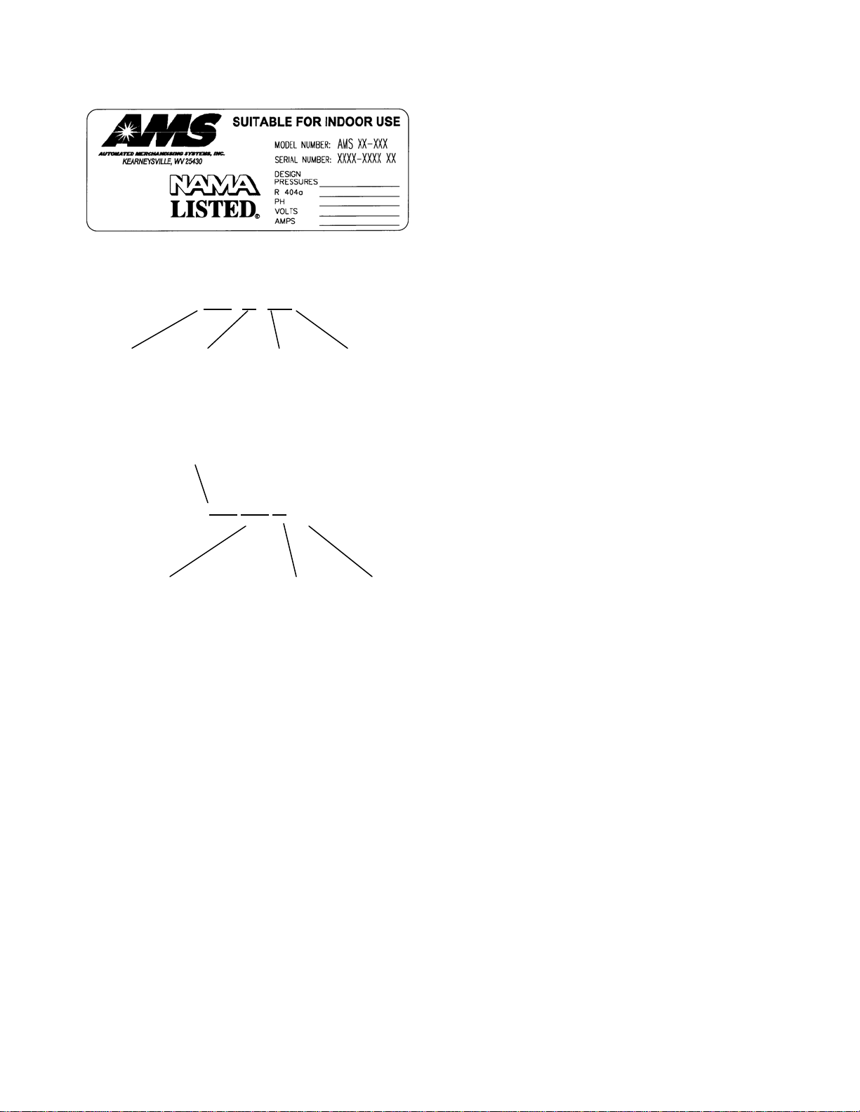
1.3 MODEL IDENTIFICATION
When requesting service, replacement parts or
technical assistance, please refer to the vendor Serial Plate
(refer to Figure 1.1). It is attached inside the door near the
upper right corner of the window and is visible from the
outside. The information contained on this plate is
necessary to determine what parts, kits, or maintenance
should be applied to your specific model.