manuals.online logo
Brands
  1. Home
  2. •
  3. Brands
  4. •
  5. B.E.G. LUXOMAT
  6. •
  7. Security Sensor
  8. •
  9. B.E.G. LUXOMAT PD4-M-1C-GH-SM User guide

B.E.G. LUXOMAT PD4-M-1C-GH-SM User guide

C
N L'L N L'L
N L'L
70
98
21
44
98
3.Puttingintooperation/Settings
Factory settings
The PD4-M-1C-GH is preset with time setting 5 min. and twilight switch
1000 Lux.
Attention:
Changes to the settings can only be made by remote control IR-PD4-GH.
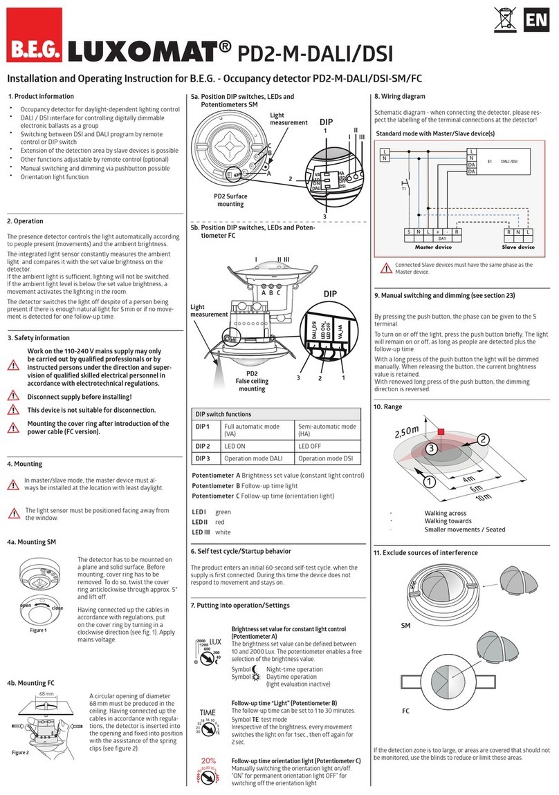
Installation and Operating Instruction for B.E.G. -Occupancy detectors PD4-M-1C/-S-GH-SM
2a.InstallationoftheLUXOMAT®
PD4-M-1C-GH-SM
4.PD4-M-1C-GH:Settingscarriedoutusingremote
control(optional)
Remote control LUXOMAT® IR-PD4-GH
1. Check Battery:
Open battery compartment by pressing the plastic
springs together and removing the battery-holder.
1.Mountingpreparations

Work on the 230V mains supply
may only be carried out by qualified
professionals or by instructed persons
under the direction and supervision of
qualified skilled electrical personnel in
accordance with electrical regulations.
Disconnect supply before installing!
The device is not suited for safe dis-
connection of the mains supply.

When in Master/Slave mode of
operation, the Master-appliance must
always be installed at the location
where there is least daylight.
Option:
Wallbracketforremotecontrol
IR-PD4-GH
2c.Selftestcycle
IR-PD4-GH
IR-PD-Mini
B.E.G. LUXOMAT®
PD4-M-1C/-S-GH-SM
The detector must be in stalled on a solid and
level surface.
The circular cover ring must be removed
prior to assembly. To do this, twist the lens (C) anti-
clockwise through approximately 5° and lift off.
Having connected up the wires in accordance with
regulations, secure the detector with 2 screws.
After installation replace the lens and lock (turn clock-
wise). Mains to be connected
.
ATTENTION:
Install the unit in such a manner that
both markings on the housing are positioned in the
longitudinal axis of the area to be monitored (e.g.
high-bay corridors)
5.PD4-M-1C-GH-SM-Dimensions
2b.Rangeindependencefromthemountingheight
Mounting
height
Range (circular detection) T=17°C
Walking across
2.00 m r = 7.50 m Ø = 15.00 m
2.50 m r = 9.00 m Ø = 18.00 m
3.00 m r = 11.00 m Ø = 22.00 m
3.50 m r = 13.00 m Ø = 26.00 m
4.00 m r = 15.00 m Ø = 30.00 m
4.50 m r = 17.00 m Ø = 34.00 m
5.00 m r = 18.50 m Ø = 37.00 m
6.00 m r = 18.50 m Ø = 37.00 m
7.00 m r = 18.50 m Ø = 37.00 m
8.00 m r = 22.00 m Ø = 44.00 m
9.00 m r = 22.00 m Ø = 44.00 m
10.00 m r = 22.00 m Ø = 44.00 m
r=radius / Ø=diameter
close
open
GB
The product enters an initial 60-second
self-test cycle, when the supply is first
connected. The occupancy detector is
ready for operation.
During the selftest cycle, the following
settings can be made:
Light stop active: (A)
Light off active: (B)
(see point 7)
Unlocking device
or or
or
or
Lock device
Settings for relay
Channel 1:








Settings for master with remote control
Reset when
open: Deletes
all values set
with the remote
control, loads
the default
settings
HA
OFF
Adjust the target value
for brightness
+
+
Target value for brightness
Automatic reading in of the current light value
as a new target light value
Sun button - specied twilight value
Daytime operation
Lag time
Pulse function, fully automatic mode active
Switch between fully automatic/semi-automatic mode
Semi-automatic mode active: Red + green LEDs ash 3x every
5 seconds
Adjust the target value for brightness
to reach the calculated target value, increase the light value by
approx. 50lux each time the button is pressed
Test mode when closed:
exited automatically after 3 minutes
Test mode when open:
not exited automatically
To deactivate: press reset
Reset when closed
The lighting relay is switched off, i.e. opened and the lag times
are reset.
Light on/off when closed
(A) The light remains on/off until movements are detected in
the detection area. After the last detected movement, the light
remains off for the duration of the set lag time. (B) If the “Light
stop” function was activated in the selftest cycle, the light is
switched off for 5 seconds (red and green LEDs flash). The device
then returns automatically to the selected operating mode (fully or
semi-automatic mode).




Explanation of button functions




HA
ON
HA
OFF
9s 2s
LED ON
LED OFF
Pulse spacing PD-Slave
2 or 9 seconds can be set for the pause between
2 pulses sent to the master. The setting can be made
with activated ( ) or deactivated ( ) LED indicator.
For devices with a separate slave input, 2 sec. can be
set.
Sensor and power supply in one
Power supply: 230 V~ ±10 %
Power consumption: < 1W
Ambient temperature: -25°C to +50°C
Degree of protection/class:
IP20 / II
Settings:
by remote control
Light values - IR-PD4-GH:
10 - 2000 Lux
Extension of the detection area:
with Slaves
Area of coverage:
circular 360°
Range of coverage Ø H 10m / T=17°C:
44 m tangential
Recommended height for mounting:
2 - 10 m
Light measurement:
daylight and artificial light
Lux values:
10 - 2000 Lux
• Relay/Channel 1 for light-connection
Type of contact:
NOC/with pretravel tungsten
contact
Contact load:
2300 W cos ϕ=1 /
1150 VA cos ϕ= 0.5, µ-Contact
Time-settings:
15 sec. - 30 min. / Test /
Impulse
Dimensions H x Ø [mm]:
98 x 65
TechnicaldataPD4-Slave-GH
Power supply: 230 V~ ±10 %
Impulse output: Optocoupler max. 2 W
Impulse duration: 2 sec. or 9sec.
Dimensions: see above
Declaration of Conformity:
The product complies with
the low voltage recommendation 2006/95/EC and the
EMV recommendation 2004/108/EC.
9.
Technicaldata
PD4-Master-1C-GH
Type SM
PD4-M-1C-GH (Master) 92245
PD4-S-GH (Slave) 92265
LUXOMAT® Remote control:
IR-PD4-GH (incl. wall bracket) 92215
IR-PD-Mini 92159
Accessory:
BSK Ball basket guard 92199
Wall bracket for remote control
as replacement 92100
IP54 Socket 92161
12.Article/Partnr./Accessory
MAN 6700 – 120911–3
13.LED-functionalindicators,fault-
finding
The functional indicators in the case of the
LUXOMAT® PD4-M-1C-GH (red and green LED‘s)
Red and green LEDs for display of the selftest cycle
(For 60 seconds after the power is switched on)
Red and green LEDs flash 1x per second
EEPROM/memory empty
Red and green LEDs flash 2x per second
EEPROM/memory written
Red LED as status display
Red LED flashes irregularly
Movements are detected in the detection area
Red LED flashes 2x per second
Detector detects brightness, light off
(depending on the operating mode)
Red LED does not light up
Detector detects darkness, light on
(depending on the operating mode)
Red LED as acknowledgement for commands
from the remote control
Red LED lights up for 1 second
Valid signal received
Red LED lights up for 0.25 seconds
Command not accepted, detector is locked
Red LED flashes extremely quickly
Command not accepted, for example if twilight value
is too light or too dark
Red and green LED as acknowledgement
for commands from the remote control
Red and green LEDs flash 3x briefly every 5 seconds
Indicates semi-automatic mode
Red and green LEDs light up alternately
Determining the light value for automatic shutdown
with sufficient daylight. (This is only indicated with a
set lag time of 30 minutes.)
8.
RangeofCoverage
11.PD4-M-1C-GH-Connections
6.Fully / Semiautomaticmode
(
for IR-PD functions see page 1
)
Fully automatic operation
In this operating mode, the lighting switches automati-
cally on and off for increased comfort, depending on
presence and brightness.
Semiautomatic operation
(Semiautomatic can only be activated via
the remote control!)
In this operating condition, in order to gain increased
savings, the lighting is energized only after being manu-
ally switched on. Switch-off takes place automatically.
The semiautomatic mode basically behaves like the fully
automatic one. However, the difference is that switching-
on must always be carried out manually!
After automatic shutdown, motion detection is active for
15 seconds in semi-automatic mode.
As many (closer-contact) buttons as desired can be wired
in parallel on the “S” button input (ON/OFF).
7.ManualSwitching
(A) To switch the light on and off, press the button
briefly. The light remains switched on or off for as long
as people are detected plus the set lag time.
(B) If the “Light stop” function was activated in the selftest
cycle, the light remains off for 5 seconds after shutdown
(red and green LEDs flash). Then the automatic function
is active again.
HA
ON
HA
OFF
44 m
360°
9.00 m
24 m
max
50
Lux
1500
Lux
ON
OFF
10.Wiringdiagrams
Standard mode with master 1-channel occupancy
detectors (NO) with R and S terminal




 




   





Optional
T1 = NO-button for semi automatic mode;
Extension of the detection area with Slave-devices
L
N
R
Slave
LL NO NO
S NR
T1
E1
This manual suits for next models

1

Other B.E.G. LUXOMAT Security Sensor manuals

B.E.G. LUXOMAT PD2-M-DALI User guide

B.E.G. LUXOMAT

B.E.G. LUXOMAT PD2-M-DALI User guide

B.E.G. LUXOMAT PD9-M-DALI/DSI-FC User guide

B.E.G. LUXOMAT

B.E.G. LUXOMAT PD9-M-DALI/DSI-FC User guide

B.E.G. LUXOMAT PD4-CAS-GH User manual

B.E.G. LUXOMAT

B.E.G. LUXOMAT PD4-CAS-GH User manual

B.E.G. LUXOMAT PICO-DALILINK 93908 User manual

B.E.G. LUXOMAT

B.E.G. LUXOMAT PICO-DALILINK 93908 User manual

B.E.G. LUXOMAT Indoor 180-R/2W UK Service manual

B.E.G. LUXOMAT

B.E.G. LUXOMAT Indoor 180-R/2W UK Service manual

B.E.G. LUXOMAT PD3-1C User guide

B.E.G. LUXOMAT

B.E.G. LUXOMAT PD3-1C User guide

B.E.G. LUXOMAT PD4-M-DIM-HVAC 16A User guide

B.E.G. LUXOMAT

B.E.G. LUXOMAT PD4-M-DIM-HVAC 16A User guide

B.E.G. LUXOMAT PD4N-KNX-DX User manual

B.E.G. LUXOMAT

B.E.G. LUXOMAT PD4N-KNX-DX User manual

B.E.G. LUXOMAT PD2N-KNX-ST-FT User manual

B.E.G. LUXOMAT

B.E.G. LUXOMAT PD2N-KNX-ST-FT User manual

B.E.G. LUXOMAT LC-Click-N 140 Owner's manual

B.E.G. LUXOMAT

B.E.G. LUXOMAT LC-Click-N 140 Owner's manual

B.E.G. LUXOMAT PD2N-KNX-DX User manual

B.E.G. LUXOMAT

B.E.G. LUXOMAT PD2N-KNX-DX User manual

B.E.G. LUXOMAT PD4-M-1C-GH-AP User manual

B.E.G. LUXOMAT

B.E.G. LUXOMAT PD4-M-1C-GH-AP User manual

B.E.G. LUXOMAT RC-plus Service manual

B.E.G. LUXOMAT

B.E.G. LUXOMAT RC-plus Service manual

B.E.G. LUXOMAT PD4-M-HCL-FC User guide

B.E.G. LUXOMAT

B.E.G. LUXOMAT PD4-M-HCL-FC User guide

B.E.G. LUXOMAT PD2N-KNX-ST User manual

B.E.G. LUXOMAT

B.E.G. LUXOMAT PD2N-KNX-ST User manual

B.E.G. LUXOMAT PD2N-KNX-BA-EM User manual

B.E.G. LUXOMAT

B.E.G. LUXOMAT PD2N-KNX-BA-EM User manual

B.E.G. LUXOMAT PD2-M-DALI/DSI-1C User guide

B.E.G. LUXOMAT

B.E.G. LUXOMAT PD2-M-DALI/DSI-1C User guide

B.E.G. LUXOMAT PD2N-KNX-ST-EM User manual

B.E.G. LUXOMAT

B.E.G. LUXOMAT PD2N-KNX-ST-EM User manual

B.E.G. LUXOMAT PD9-M-1C-FC User guide

B.E.G. LUXOMAT

B.E.G. LUXOMAT PD9-M-1C-FC User guide

B.E.G. LUXOMAT PD4-CAS-GH User manual

B.E.G. LUXOMAT

B.E.G. LUXOMAT PD4-CAS-GH User manual

B.E.G. LUXOMAT PD4N-DALILINK User manual

B.E.G. LUXOMAT

B.E.G. LUXOMAT PD4N-DALILINK User manual

B.E.G. LUXOMAT PD2N-KNX-BA User manual

B.E.G. LUXOMAT

B.E.G. LUXOMAT PD2N-KNX-BA User manual

B.E.G. LUXOMAT PD4N-DALILINK User manual

B.E.G. LUXOMAT

B.E.G. LUXOMAT PD4N-DALILINK User manual

Popular Security Sensor manuals by other brands

SMC Networks SMCDW01-Z quick start guide

SMC Networks

SMC Networks SMCDW01-Z quick start guide

SANJIANG JTF-GDM-936E Operation manual

SANJIANG

SANJIANG JTF-GDM-936E Operation manual

Powerfix Profi 271367 Operation and safety notes

Powerfix Profi

Powerfix Profi 271367 Operation and safety notes

F&F DRM-02 quick start guide

F&F

F&F DRM-02 quick start guide

Niko 351-25451 manual

Niko

Niko 351-25451 manual

IFM Electronic OPL2 Series operating instructions

IFM Electronic

IFM Electronic OPL2 Series operating instructions

MSA SOLARIS operating manual

MSA

MSA SOLARIS operating manual

PWNIE Express Pwn Plug R3 user manual

PWNIE Express

PWNIE Express Pwn Plug R3 user manual

schmersal EX-BNS 33 operating instructions

schmersal

schmersal EX-BNS 33 operating instructions

FrSky FLVS ADV instruction manual

FrSky

FrSky FLVS ADV instruction manual

Rielta STEKLO-3RK installation guide

Rielta

Rielta STEKLO-3RK installation guide

Mhouse MAD5 Instructions for installation

Mhouse

Mhouse MAD5 Instructions for installation

urmet domus sinthesi steel 1083/14 manual

urmet domus

urmet domus sinthesi steel 1083/14 manual

Hochiki RHD-E-AS instruction manual

Hochiki

Hochiki RHD-E-AS instruction manual

Hytronik HCD038+HIR17 Installation and instruction manual

Hytronik

Hytronik HCD038+HIR17 Installation and instruction manual

Honeywell PEHA LightSpot Mid Range Series Installation and commissioning instructions

Honeywell

Honeywell PEHA LightSpot Mid Range Series Installation and commissioning instructions

BST Flamonitec IFC 400 operating manual

BST

BST Flamonitec IFC 400 operating manual

GESTRA TURBISCOPE OR 52/5 datasheet

GESTRA

GESTRA TURBISCOPE OR 52/5 datasheet

manuals.online logo
manuals.online logoBrands
  • About & Mission
  • Contact us
  • Privacy Policy
  • Terms and Conditions

Copyright 2025 Manuals.Online. All Rights Reserved.