manuals.online logo
Brands
  1. Home
  2. •
  3. Brands
  4. •
  5. B.E.G. LUXOMAT
  6. •
  7. Security Sensor
  8. •
  9. B.E.G. LUXOMAT PD9-M-DALI/DSI-FC User guide

B.E.G. LUXOMAT PD9-M-DALI/DSI-FC User guide

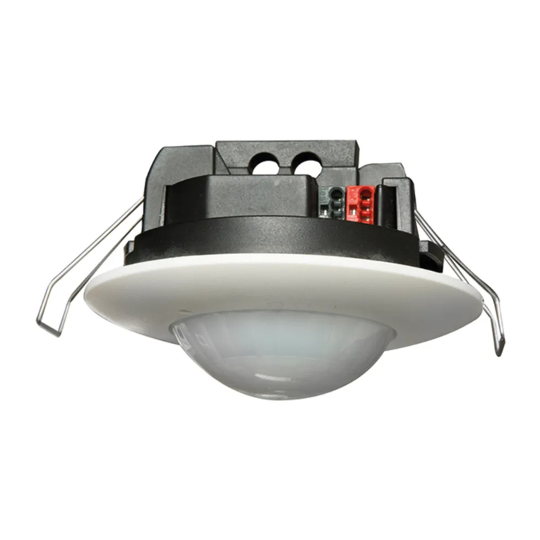
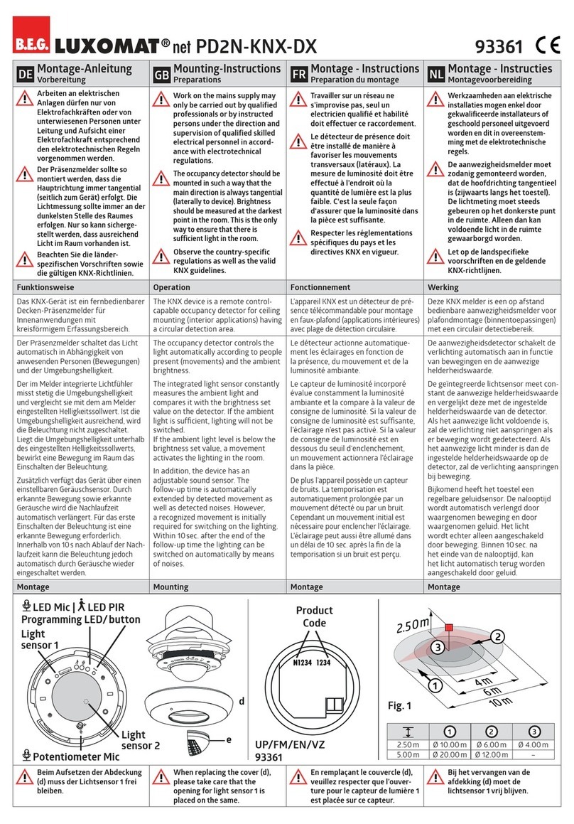
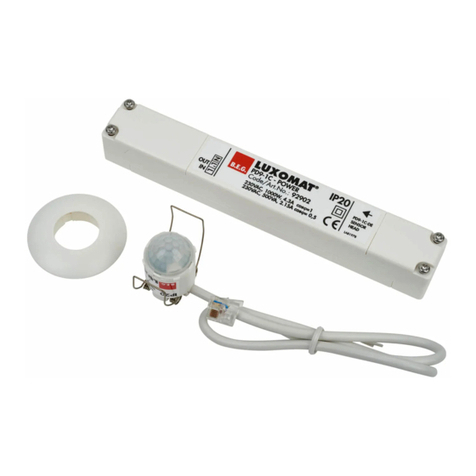
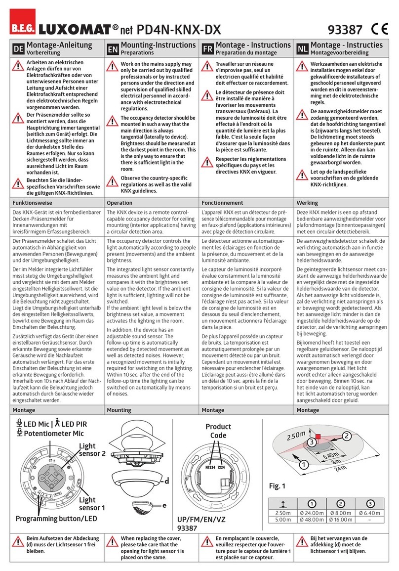
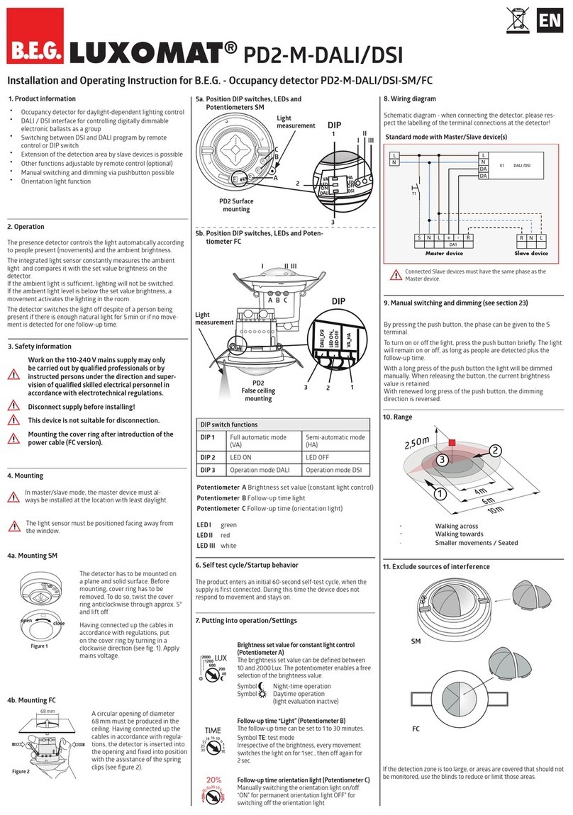
Installation and Operating Instruction for B.E.G. - Occupancy detectors PD9-M-DALI/DSI-FC und PD9-M-DALI/DSI-GH-FC
LUXOMAT®PD9-M-DALI/DSI(-GH)
1b. Mounting preparations
Work on the 230 V mains supply
may only be carried out by quali-
fied professionals or by instructed
persons under the direction and
supervision of qualified skilled elec-
trical personnel in accordance with
electrotechnical regulations.
Disconnect supply before installing!
When in Master/Slave mode of
operation, the Master-appliance
must always be installed at the
location where there is least
daylight.
Option:
Wall bracket for remote control
IR-PD-DALI
1a. Features
* For connection of up to 50 lamps
* Suitable for dimmable electronic
ballasts and control modules
* DALI/DSI output
* Constant light control
* Manual switching/dimming
* Semi or completely automatic
operation
* Luminance (brightness) set point,
switch-off delay time for LIGHT and
orientation-light adjustable
* Sensor and power sections in one
housing
* Infrared remote control
2a. Installation LUXOMAT®PD9-M-
DALI/DSI(-GH)-FC
The detector has
been designed and
developed specifi-
cally for installation in
suspended ceilings.
A circular opening of
diameter min. 34 mm
must be produced in
the ceiling.
Having connected the cables in accordance with the
regulations, connect the power supply via the RJ11
plug. Therefore, open the power supply with the help
of the screws and close it afterwards. After that, put
the power supply through the opening in the ceiling
and mount the sensor onto the ceiling according to
figure.
3.
Settings carried
out using remote
control (optional)
Remote control LUXOMAT®
IR-PD-DALI
Check Battery:
Open battery compartment
by pressing the plastic
springs together and remo-
ving the battery-holder.
The LUXOMAT®PD9-M-
DALI/DSI(-GH) enters an
initial 60-second self-test
cycle, when the supply is
first connected. The oc-
cupancy detector is ready
for operation.
2b. Self test cycle
Walking across
Walking towards
Seated
8. Range of Coverage
PD9-M-DALI/DSI
7. Dimensions
PD9-M-DALI/DSI PD9-M-DALI/DSI-GH
PD9-M-DALI/DSI-GH
6. Exclude sources of
interference
PD9-FC PD9-GH-FC
In case the sensing area of the
LUXOMAT®
PD9-M-DALI/DSI(-GH)
is
too large or areas are being covered
that should not be monitored, the range
can be reduced or limited through use
of the enclosed masking clips.
Overview range in dependence from the mounting
height
Mounting
height
Range (circular detection) T=18°C
walking across
5.00 m Ø=3.00 m
6.00 m Ø=3.50 m
7.00 m Ø=4.20 m
8.00 m Ø=4.80 m
9.00 m Ø=5.40 m
10.00 m Ø=6.00 m
GB
10 m
6 m
2.50 m
10 m
360°
2.50 m
32
1
4. Settings by remote control when open 5. Key functions in closed state
360°
5.40 m
5.40 m
RJ
9.00 m
quer zum Melder gehen
frontal zum Melder gehen
Unterkriechschutz
22 - 30 mm
min. 34 mm
165 mm
24 mm
24 mm
45
25
12 16
45
24
25
16
Unlocking device – Activation of
the programming mode
Locking device – Exit program-
ming mode
Resetting when
open
: Deletes
all values set
with the remote
control, light
OFF.
Follow-up time light
Orientation lighting on/off
Automatic reading in the
current light value as new
luminance set point
Permanent protection against
sabotage
LED ashes
or Dimming of the lighting on the
desired luminance value
Adjusting of the luminance set point
+ / – small steps
+/ –big steps
1
min to 30
min
max
50
Lux
1500
Lux
ON
OFF
max
50
Lux
1500
Lux
ON
OFF
DSI/
DALI
Switching between DSI and
DALI program
or
+–
Fully automatic/semi automatic
mode => (see page 2, point 9)
Preset/user mode
=> (see page 2, point 10)
max
50
Lux
1500
Lux
ON
OFF
Orientation lighting and its
follow-up time
to
1
min
10
min
max
50
Lux
1500
Lux
ON
OFF
t < 5 sec.
Lock device
Test mode
Reset to deactivate
Resetting when closed
The lighting relay is switched off, i.e. opened and the
follow-up times reset.
Permanent protection against sabotage
This function blocks the unit permanently (green LED is illumi-
nated). This operating mode can only be activated during the
period of 5 seconds after pressing the “lock“ button. This status
will only permit actuating the function “Light on/Light off”.
The procedure for leaving this mode is as follows:
1. Switch off the current
2. Apply current for 31 – 59 seconds
3. Switch of the current again
4. Apply current
5. Open detector
Light on/off when closed
=> (see page 2, point 9)
The light will remain switched on/off for as long as movements
are detected in the areas of coverage. Once the last movement
has been detected, the light will remain on for the duration of
the follow-up time as per setting.
The appliance will then return independently to the mode
selected (Fully or Semi-automatic).
max
50
Lux
1500
Lux
ON
OFF
t < 5 sec.
Power supply: 230 V~ ±10 %
Power consumption: < 1W
Ambient temperature: -25°C to +50°C
Degree of protection/class:
IP20 / II
Settings:
by remote control
Light values - IR-PD-DALI:
50 - 1500 Lux
Extension of the detection area:
with Slaves
Area of coverage:
circular 360°
Range of coverage Ø H 2.50 m / T = 18°C:
PD9-M-DALI/DSI
seated
2.50 m
/
tangential
10 m /
radial
6m
PD9-M-DALI/DSI-GH max. Ø
5.40 m
Recommended height for mounting:
PD9-M-DALI/DSI
2 - 3 m
PD9-M-DALI/DSI-GH 5 - 10 m
Light measurement:
mixed light, daylight and artificial light
• DALI-Output
digital BUS control wire, 2-core, no polarity
(broadcast only)
Max. no. of series-connected electronic ballasts:
up to 50
Time-settings:
1 - 30min. / Test
Dimensions H x Ø [mm]:
PD9-M-DALI/DSI
Ø 45 x H 28 mm
PD9-M-DALI/DSI-GH
Ø 45 x H 40 mm
Power supply L 165 x W 24 x H 24 mm
Declaration of Conformity:
The product complies with the
low voltage recommendation 2006/95/EC and the EMV
recommendation 2004/108/EC.
15.
Technical data
PD9-M-DALI/DSI(-GH)
13. Wiring diagram
14. PD9-M-DALI/DSI(-GH) – Connections
Circuit diagram
MAN 5976 – 270912–2
10. Manual Dimming – Preset / User
(for IR-PD-DALI functions see page 1)
You can dim manually by pressing the pushbutton for
a long time (> 2 sec). When the button is released,
the current dimming value is retained. Upon renewed
dimming, the dimming direction is reversed.
PRESET –the luminance set point is set during start-up
operation by the installer and remains unchanged.
The luminance set- point congured through manual
dimming is only applied for the time being.
Caution:
The constant light regulation is now deactivated!
The currently set articial light is retained independent
of the ambient/daylight brightness!
After switching off and then back on, the originally set
luminance set-point is reset = constant light regulation
is activated.
USER – can only be activated via the remote control!
The luminance set-point is changed upon each manual
dimming and re-adjusted by the user (Conformation
through relay clicking!)
The constant light regulation remains activated!
9. Fully / Semi automatic mode
(for IR-PD-DALI functions see page 1)
Fully automatic operation
In this operating mode, the lighting switches automati-
cally on and off for increased comfort, depending on
presence and brightness.
Semiautomatic operation
(Semiautomatic can only be activated via the remote
control!)
In this operating condition, in order to gain increased
savings, the lighting is energized only after being manu-
ally switched on.
Switch-off takes place automatically.
The semiautomatic mode basically behaves like the fully
automatic one. However, the difference is that switching-
on must always be carried out manually!
As many (closer-contact) buttons as desired can be wired
in parallel on the “S” button input (ON/OFF Dimm).
11. Manual Switching
You can switch the lighting on and off manually by
pressing the pushbutton for a short time. It will stay on or
off as long as people are detected plus the congured
follow up time.
L
N
S1 S2
up to 50 EBs
EB 1
EB 2
EB 50
For T5 and
T8 uorescent
lamps
SLAVE
20%
LUXOMAT®IR-PD-DALI
RESET TEST
30
min
15
min
10
min
5
min
1
min
OFF
60
min
30
min
10
min
1
min
ON
-
-
-
max
++
+
min
DSI/
DALI
PD9-M-DALI/DSI
WE RECOMMEND THAT BEFORE DIMMING OF THE CONNECTED
LIGHTS A 100 hBURN IN (T5 TUBES OR 80 HOURS FOR T8 TUBES)
FUNCTION TAKES PLACE. THIS CAN BE IGNORED BY USING THE
REMOTE CONTROL TO DEACTIVATE.
THE LIFESPAN OF THE LAMPS CAN BE REDUCED IF THE BURN IN
DOES NOT TAKE PLACE.
16. LED-functional indicators
max
50
Lux
1500
Lux
ON
OFF
max
50
Lux
1500
Lux
ON
OFF
max
50
Lux
1500
Lux
ON
OFF
S
R
NNL
S
T
L'NL
DALI
DSI
D D





 



 




   

 



Standard mode with master DALI occupancy detectors
Type FC
PD9-M-DALI/DSI – Master 92920
PD9-M-DALI/DSI-GH – Master 92938
PD9-S – Slave 92905
PD9-S-GH – Slave
92928
LUXOMAT®Remote control:
IR-PD-DALI (incl. wall bracket) 92094
Accessory:
Wall bracket for remote control as replacement
92100
Blind PD9-GH for 180° detection 33207
12. Article / Part nr. / Accessory
LED function indicators
Process Standard
mode Double-locked
Initialisation time
unprogrammed Red flashes Green
flashes
Initialisation time
programmed
Red flashes
quickly
Green flashes
quickly
Motion detection
Red flashes
on each
detected
movement
Green flashes
on each
detected
movement
Too bright detected
Red flashes
2x each
second
Green flashes
2x each
second
Too bright / too dark /
undefined in opened state
Red flashes
very quickly
Green flashes
very quickly
Switching DALI/DSI
DSI active
Red shines
3 sec.
Switching DALI/DSI
DALI active
Green shines
3 sec.
Switching HA/VA
VA active
Red shines
3 sec.
Switching HA/VA
HA active
Green shines
3 sec.
Switching Preset/User
Preset active
Red shines
3 sec.
Switching Preset/User
User active
Green shines
3 sec.
IR signal valid received Red shines
3 sec.
IR signal invalid received Red shines
0,5 sec.
This manual suits for next models

1

Other B.E.G. LUXOMAT Security Sensor manuals

B.E.G. LUXOMAT PD4N-DALILINK User manual

B.E.G. LUXOMAT

B.E.G. LUXOMAT PD4N-DALILINK User manual

B.E.G. LUXOMAT PD2-M-DALI/DSI-1C User guide

B.E.G. LUXOMAT

B.E.G. LUXOMAT PD2-M-DALI/DSI-1C User guide

B.E.G. LUXOMAT PD4-M-HCL-FC User guide

B.E.G. LUXOMAT

B.E.G. LUXOMAT PD4-M-HCL-FC User guide

B.E.G. LUXOMAT PD9-M-1C-FC User guide

B.E.G. LUXOMAT

B.E.G. LUXOMAT PD9-M-1C-FC User guide

B.E.G. LUXOMAT PD4-CAS-GH User manual

B.E.G. LUXOMAT

B.E.G. LUXOMAT PD4-CAS-GH User manual

B.E.G. LUXOMAT PD2N-KNX-ST-FT User manual

B.E.G. LUXOMAT

B.E.G. LUXOMAT PD2N-KNX-ST-FT User manual

B.E.G. LUXOMAT PD3-1C User guide

B.E.G. LUXOMAT

B.E.G. LUXOMAT PD3-1C User guide

B.E.G. LUXOMAT PD4-M-1C-GH-SM User guide

B.E.G. LUXOMAT

B.E.G. LUXOMAT PD4-M-1C-GH-SM User guide

B.E.G. LUXOMAT PD4-CAS-GH User manual

B.E.G. LUXOMAT

B.E.G. LUXOMAT PD4-CAS-GH User manual

B.E.G. LUXOMAT PICO-DALILINK 93908 User manual

B.E.G. LUXOMAT

B.E.G. LUXOMAT PICO-DALILINK 93908 User manual

B.E.G. LUXOMAT PD2N-KNX-BA User manual

B.E.G. LUXOMAT

B.E.G. LUXOMAT PD2N-KNX-BA User manual

B.E.G. LUXOMAT PD4N-DALILINK User manual

B.E.G. LUXOMAT

B.E.G. LUXOMAT PD4N-DALILINK User manual

B.E.G. LUXOMAT PD2N-KNX-BA-EM User manual

B.E.G. LUXOMAT

B.E.G. LUXOMAT PD2N-KNX-BA-EM User manual

B.E.G. LUXOMAT PD2N-KNX-ST User manual

B.E.G. LUXOMAT

B.E.G. LUXOMAT PD2N-KNX-ST User manual

B.E.G. LUXOMAT PD2N-KNX-ST-EM User manual

B.E.G. LUXOMAT

B.E.G. LUXOMAT PD2N-KNX-ST-EM User manual

B.E.G. LUXOMAT PD2N-KNX-DX User manual

B.E.G. LUXOMAT

B.E.G. LUXOMAT PD2N-KNX-DX User manual

B.E.G. LUXOMAT RC-plus Service manual

B.E.G. LUXOMAT

B.E.G. LUXOMAT RC-plus Service manual

B.E.G. LUXOMAT LC-Click-N 140 Owner's manual

B.E.G. LUXOMAT

B.E.G. LUXOMAT LC-Click-N 140 Owner's manual

B.E.G. LUXOMAT PD2-M-DALI User guide

B.E.G. LUXOMAT

B.E.G. LUXOMAT PD2-M-DALI User guide

B.E.G. LUXOMAT PD4-M-1C-GH-AP User manual

B.E.G. LUXOMAT

B.E.G. LUXOMAT PD4-M-1C-GH-AP User manual

B.E.G. LUXOMAT PD4N-KNX-DX User manual

B.E.G. LUXOMAT

B.E.G. LUXOMAT PD4N-KNX-DX User manual

B.E.G. LUXOMAT Indoor 180-R/2W UK Service manual

B.E.G. LUXOMAT

B.E.G. LUXOMAT Indoor 180-R/2W UK Service manual

B.E.G. LUXOMAT PD4-M-DIM-HVAC 16A User guide

B.E.G. LUXOMAT

B.E.G. LUXOMAT PD4-M-DIM-HVAC 16A User guide

Popular Security Sensor manuals by other brands

SIM SIM-120 installation manual

SIM

SIM SIM-120 installation manual

Scott Safety MultiFlame FV-40 Series user guide

Scott Safety

Scott Safety MultiFlame FV-40 Series user guide

Petzl ASCENSION manual

Petzl

Petzl ASCENSION manual

Commercial Electric CE-2701-WH Quick reference guide

Commercial Electric

Commercial Electric CE-2701-WH Quick reference guide

Reno AX2DL-XP operating instructions

Reno

Reno AX2DL-XP operating instructions

Siemens OH720 Technical manual

Siemens

Siemens OH720 Technical manual

Stahl YL60 Series operating instructions

Stahl

Stahl YL60 Series operating instructions

Comelit RFDT12CE Technical manual

Comelit

Comelit RFDT12CE Technical manual

Busch-Wachter 6847 220 MasterLINE operating instructions

Busch-Wachter

Busch-Wachter 6847 220 MasterLINE operating instructions

Essence CareHome ES700PIR user guide

Essence

Essence CareHome ES700PIR user guide

Stanley FATMAX FMHT77652 user manual

Stanley

Stanley FATMAX FMHT77652 user manual

Clas Ohlson ST-09 instruction manual

Clas Ohlson

Clas Ohlson ST-09 instruction manual

Olympia ZLD-28 manual

Olympia

Olympia ZLD-28 manual

RKI Instruments 35-3001-05 Series Operator's manual

RKI Instruments

RKI Instruments 35-3001-05 Series Operator's manual

Telefire TBD-8100 Technical manual

Telefire

Telefire TBD-8100 Technical manual

Intermatic IOS-DSR manual

Intermatic

Intermatic IOS-DSR manual

CST/BERGER LD400 Original instructions

CST/BERGER

CST/BERGER LD400 Original instructions

CT BE UP manual

CT

CT BE UP manual

manuals.online logo
manuals.online logoBrands
  • About & Mission
  • Contact us
  • Privacy Policy
  • Terms and Conditions

Copyright 2025 Manuals.Online. All Rights Reserved.