Badger Basket Liffey 22kW Twin User manual

Liffey 22kW Twin
Installation Manual
BADGER EV
Enterprise House, Manchester Science Park, Lloyd St N, Manchester M15 6SE
www.badger-ev.com
WWW.BADGER-EV.COM

Leading The Charge
CONTENTS
●
●
●
P-03
P-04
P-05
P-06
Important safety instructions
●P-01
●P-08
P-08
P-08
P-09
P-09
P-09
P-10
P-11
●
●
●
●
P-15
P-18
P-19
P-20
P-22
P-23
P-24
●
●
●
●
●
●
P-25
P-26
P-27
P-31
●
●
●
●
2. Product Introduction
1. Safety Information 01
03
07
15
P-25
25
●
●
●
●
●
●
2.1. Product Appearance
2.2. Parameter table
2.3. Product Features
2.4. Protection Functions
3. Installation Instructions
3.1. Installation Considerations
3.2. SIM Card Installation
3.3. Minimum Installation Requirements
3.4. Installation Position
3.5. Installation Height
3.6. Power Supply
3.7. Accessories List
3.8. Installation Step
4. Web configuration
4.1. Connection Configuration
4.2. OCPP Server Configuration
4.3. The Parameter Configuration
4.4. DLB Box Configuration
4.5. Enter the RFID configuration
4.6. Reset the Password
4.7. WPS Connection Method
4.8. Exit AP Mode
5. Operating instructions
5.1. Button Functions
5.2. Buzzer
5.3. LED Lights Display
5.4. Firmware Update via Bluetooth in BE Smart App

P-01
1. Safety Information
Important safety instructions: this document contains important instructions
and warnings that must be followed when installing and maintaining the Liffey
EV Charger.
Warning
Read this entire mandatory document before installing or using the Liffey EV Charger.
Unsupervised children should not be allowed near the EV Charger.
The Liffey EV Charger must be grounded through a permanent wiring system or an
equipment grounding conductor.
Do not install or use the EV Charger near flammable, explosive, harsh, or combustible
materials, chemicals, or vapors.
Use the EV Charger only within the specified operating parameters.
Never spray water or any other liquid directly onto the EV Charger. Never spray any liquid
into the Type 2 socket on the charger.
Do not use the EV Charger if it is defective, appears cracked, frayed, broken, or otherwise
damaged, or fails to operate, or continue operation.
Do not attempt to disassemble, repair, tamper with, or modify the EV Charger. The EV
Charger is not user serviceable, contact BPE for any repairs or modification.
Please take care while transporting the EV Charger. Do not subject it to drops or any impact,
crushing, tangle, dragging or water. This is important to prevent damage to it or any
components.
Do not touch the EV Charger’s Type 2 socket with any sharp metallic objects, such as wires,
tools, or needles.
Do not forcefully fold or apply pressure to any part of the EV Charger or damage it with sharp
objects.
Do not insert foreign objects into any part of the EV Charger.
Use of the EV Charger may affect or impair the operation of any medical or implantable
electronic devices, such as an implantable cardiac pacemaker or an implantable cardioverter
defibrillator. Check with your electronic device manufacturer concerning the effects that
charging may have on such electronic devices before using the EV Charger.
Cautions
Do not use private power generators as a power source for charging.
Incorrect installation and testing of the EV Charger could potentially damage either the
vehicle's Battery and/or the EV Charger itself. Any resulting damage is excluded from New
Vehicle Limited Warranty and the EV Charger Limited Warranty.
Do not operate the EV Charger in temperatures outside its operating range of -25℃ to +50℃
Type 2 to Type 1 adapter leads are not allowed to be used.
Notes
Ensure that the EV Charger's charging cable is positioned so it will not be stepped on, driven
over, tripped on, or subjected to damage or stress.
Do not use cleaning solvents to clean any of the EV Charger's components. The outside of
the EV Charger, the charging cable, and the connector end of the charging cable should be
periodically wiped with a clean dry cloth to remove any accumulation of dirt or dust.
Be careful when removing front fascia, do not use a screw driver as this will damage it. Use
the included Fascia Removal Tool in the box.
P-02
1. Safety Information
P-04P-03
2. Product Introduction
2.1. Product Appearance
2
1
3
4
5
6
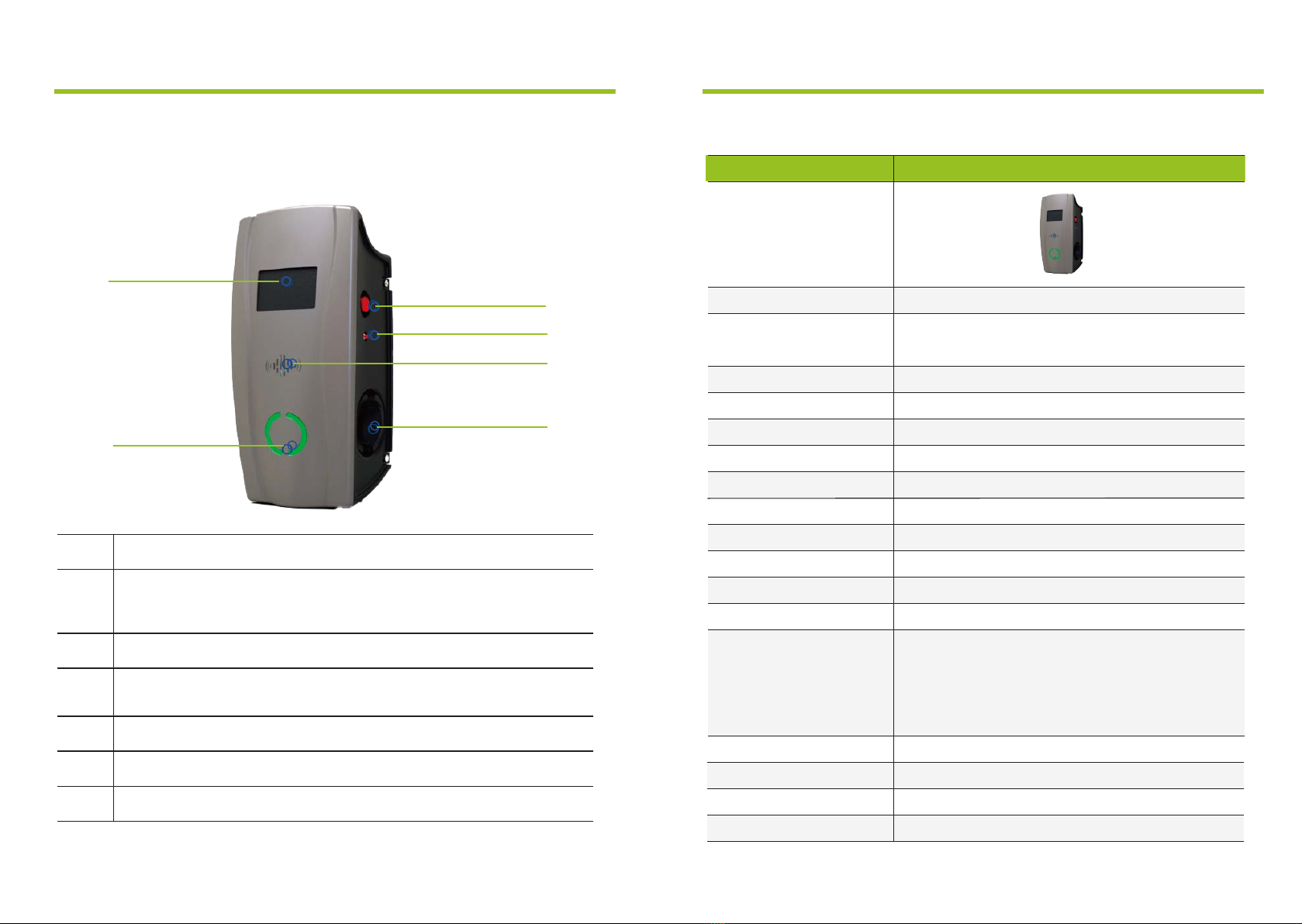
LCD Screen
Emergency Shutdown Button
(When the button is pressed, the EV Charger will stop charging,
then rotate the button to pop it up and reset it.)
DC Leakage Test Button
(For WPS connection and leakage test.)
RFID card reader
Type 2 socket
LED light
Number
1
2
3
4
5
6
2. Product Introduction
Description
2.2. Parameter table
Rate Charging Current
Standby Power Consumption
Operating Temperature
Operating Humidity
IP Protection
Safety Protection
Operating Altitude
Charger Dimension
Gross Weight
Leakage Detection
Maximum Power
Input voltage/Output voltage
Display
Tethered/Socket
Meter
Input frequency
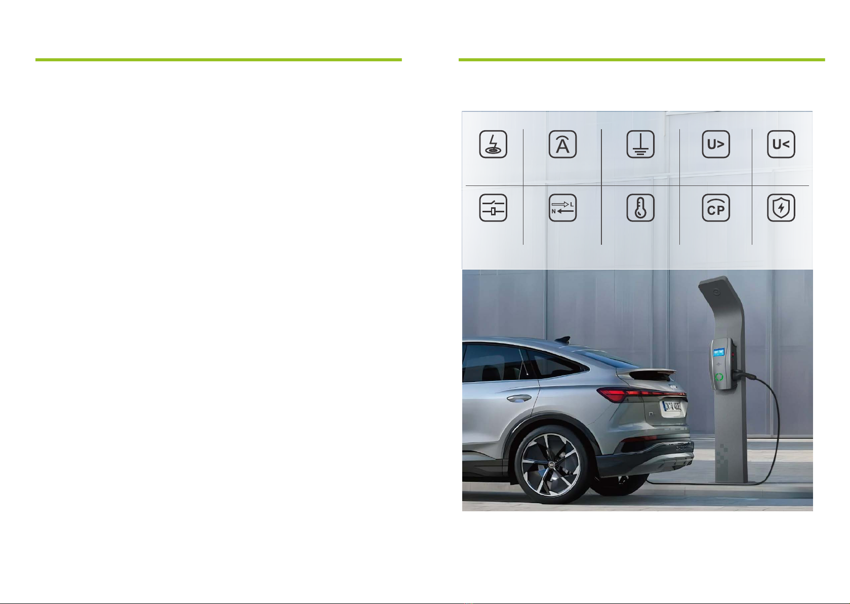
Leakage Protection、Over Current Protection、Ground
Protection、Over Voltage Protection、Under Voltage
Protection、Contactor Adhesion Protection、Neutral and
Live Wire Reverse Connection Protection、Over
Temperature Protection、CP Signal Abnormal
Protection、Lightning Protection
6-32A
4G:<8W Wi-Fi:<6W
-25℃~50℃
5%-95%
IP55
<2000M
Height:470mm Width:225.3mm Depth:177.3mm
9.8KG
TYPE A+DC6mA leakage sensor built-in
LCD Screen + LED Lights
50Hz/60Hz
2 x Socket
2 x MID Meter
400VAC
3-Phase
2 x 22kW
BPE Liffey Dual Socket BPE-LFY-Dual-22kW
2. Product Introduction
P-06P-05
2. Product Introduction
2.4. Protection Functions
UnderVoltage
Protection
Lightning
Protection
Over
Temperature
Protection
Ground
Protection
OverCurrent
Protection
Neutraland
LiveWireReverse
Connection
Protection
OverVoltage
Protection
CPSignal
Abnormal
Protection
Leakage
Protection
Contactor
Adhesion
Protection
2.3. Product Features
Open Cover Detection: If the cover is opened, the Charger will display red light alarm
and stop any charging session. A warning message will also appear in the App
LCD Display
Two built-in MID meters
Motion Detector: When a person is close to the Charger, the LCD screen will light up, this
can reduce the standby consumption and extend the service life
Double socket: Charge two EVs at the same time with up to 22kW per socket
OCPP 1.6: Able to connect to any OCPP software on the market.
Integrated PEN Fault Detection: No need for installing an Earth rod
IP55: Waterproof and ideal for outdoor installations
Leakage Protection: Built-in Type A RCD + 6mA DC leakage sensor
Over Temperature Detection: In the event that the temperature rises to unsafe levels, the
charger will cease operating
WPS Wi-Fi connection: Simplifies the Wi-Fi connection process
●
●
●
●
●
●
●
●
●
●
●

P-07 P-08
Warning
This BPE EV charger must be grounded via a permanent electrical system or equipment
grounding conductor.
3. Installation Instructions3. Installation Instructions
●
●
●
●
●
●
●
●
●
3.1. Installation Considerations
Note: Throughout the manual, "conduit" is used as the standard term for the protective tubing
that houses the service wiring. In regions where conduit is not used (Europe for example), a
cable comprised of service wiring enclosed in a protective jacket may be substituted for
conduit if allowed by local regulations.
Here are some additional guidelines:
Conduit needs to be metal and flame retardant.
Use an appropriate circuit breaker.
To keep the housing weatherproof, use cable glands.
3.2. SIM Card Installation
●Note: If you need to use 4G mode, please install a Micro SIM card into
the circuit board located inside of the charger.
3.3. Minimum Installation Requirements
Installation of the wall charger requires that you:
Calculate the existing electrical load to determine the maximum operating current available
for the EV charger.
Calculate the cable run distance to ensure minimal voltage drop.
Obtain any necessary permits from the local authority that has jurisdiction and confirm that
all regulations are adhered to throughout the installation.
Use only copper conductors.
Use copper wire that meets the specifications of local wiring regulations. The selected cable
must be capable of withstanding continuous loads of up to 40A at all times. The selected
circuit protection device must incorporate an appropriate wall-mounted residual current
device (RCD) and corresponding electrical load over current protection.

P-09 P-10
●
●
●
●
●
●
●
●
3.4. Installation Position
Ensure that the parking space is within reach of the charging cable.
Ensure there is enough clearance around the charger for the installation and maintenance
to be carried out.
For outdoor installations, weather protection is recommended but not mandatory.
Install in a well-ventilated space. Avoid installation in enclosed boxes or close to high
power appliances.
Do not select an installation site that is near explosive, flammable or any other hazardous
material.
3.5. Installation Height
Maximum height (indoor and outdoor): 1.5 m
Recommended height: ~1.2 m
3.6. Power Supply
400V three-phase power supply with neutral line
All three phases (L1, L2 and L3) and the neutral line should be
connected to the charger and the voltage of each phase to the neutral
should be 230V.
L1
L2
L3
230V
N
PE
400V
230V
230V
3. Installation Instructions 3. Installation Instructions
① ② ③ ④
⑤ ⑥ ⑦ ⑧
⑨
EV charger
X1
Mounting braket
X1
M32*1.5 cable gland
X1
M6*8 screws 8*40 socket head
screws and anchorings
X4 X8
Position template
X1
Fascia Removal
Tool
X1
Water-proof cover
X1
RFID card (optional)
X2
3.7. Accessories List

P-12P-11
3. Installation Instructions
Wall
≥0.5M
~1.2M
Floor Level
Drill
Side of wall
The 8 points
on the position
plate
Wall
Screwdriver
Mounting
Bracket
8*40
Expansion Bolts
Step 1
Positioning
Ensure the bottom of the positioning plate is 1.2 m
(recommended) off the ground.
Drilling pilot holes
Drill the holes according to the instructions on the
position template for different installation and
wiring types.
Step 2
Installing the Mounting Bracket
Insert the 8*40 Socket head screw anchors into the
holes and use the screw driver fix the Mounting
Bracket onto the wall.
3.8. Installation Step
3.8.1. Step-by-step Installation Instructions
(bottom entry wiring)
3. Installation Instructions
3.8.1. Step-by-step Installation Instructions
(bottom entry wiring)
Step 3
lnstall the EV Charger to the Mounting Bracket
Align the side holes of EV charger to the
bracket's side holes.
lnstallation
Use the 4pcs M6*8 screws to fix the EV charger
to the mounting bracket as shown in the
diagram (Screws torque 1.5NM-2.0NM).
Left hole position Right hole
position
M6*8 bolts
Step 4
Wiring
Note: lt is the installer's responsibility to identify
whether additional grounding is required to
ensure that local regulations are met. Grounding
must be installed at the power source and not
at the cable entry to the EV Charger.
Using a screwdriver, loosen the screws on the
EV charger cover and remove it. Wire the cable
into the terminal according to the diagram.
L1 L2 L3 N PE L1 L2 L3 N
(wiring from the left
to the right)
3 phase wiring
diagram
L1 L2 L3 N PE
Single Cable
(13 sq/mm to 16 sq/mm)
(6 sq/mm )
Dual Cables
P-13 P-14
3.8.2. Step-by-step Installation Instructions
(rear entry wiring)
Wall
≥0.5M
~1.2M
Floor Level
Drill
Side of wall
The 8 points
on the
position plate
Hole for rear entry
Screwdriver
8*40
Expansion Bolts
Mounting
Bracket
3. Installation Instructions 3. Installation Instructions
3.8.2. Step-by-step Installation Instructions
(rear entry wiring)
Step 3
lnstall the EV Charger to the mounting bracket
Find the knock-out hole on the back of the EV
charger and use a drill to remove it.
Use the 4pcs M6*8 screws to fix the EV charger
to the mounting plate as picture shows (Screws
torque 1.5NM-2.0NM).
Left hole position Right hole
position
Back of EV charger
perforating
as image
M6*8 bolts
Step 4
Wiring
Note: lt is the installer's responsibility to identify
whether additional grounding is required to
ensure that local regulations are met. Grounding
must be installed at the power source and not at
the cable entry to the EV Charger.
Using a screwdriver, loosen the screws on the
EV charger cover and remove it. Wire the cable
into the terminal according to the diagram.
Insert cable through hole and
connect to the wiring terminal
Step 1
Positioning
Ensure the bottom of the positioning plate is 1.2 m
(recommended) off the ground.
Drilling pilot holes
Drill the holes according to the instructions on the
position template for different installation and
wiring types.
Step 2
Installing the Mounting Bracket
Insert the 8*40 Socket head screw anchors into the
holes and use the screw driver fix the Mounting
Bracket onto the wall.
L1 L2 L3 N PE L1 L2 L3 N
(wiring from the left
to the right)
3 phase wiring
diagram
L1 L2 L3 N PE
Single Cable
(13 sq/mm to 16 sq/mm)
(6 sq/mm )
Dual Cables

P-16P-15
4. Web configuration
4.1. Connection Configuration
4.1.1. Enter the Configuration Mode
When the charger is powered on for the first time, it will automatically enter the
Configuration Mode. If you experience any issues during the setup, you can always
reset the charger by:
1) Power OFF the charger
2) Hold down the Emergency Stop Button and the small red button at the same time
3) Power ON the charger
4.1.2. Connect to the Wi-Fi Network
Connect to the Wi-Fi AP Network that is emitted from the charger through your computer or mobile phone
(The Wi-Fi SSID is "EVSEXXXXXXXXXXXX" and the default password is "12345678").
(You can reset the password to default: Power ON the charger; find the hard reset button on the PCB inside
of the EV charger. Press it and hold for 5s.)
EVSE-25555B69666C
No Internet, safe
Attributes
Disconnect
4. Web configuration
Open your browser and type 192.168.1.1 into the URL bar at the top. We recommend using Google
Chrome for better compatibility.
4.1.3. Accessing the Charger through a Browser
4.1.4. Enter the Configuration Page
Go to the configuration page, here you can change the charger's settings
Table of contents
Other Badger Basket Batteries Charger manuals


