BAK Thermoplastic Welding Technology AG 4
Safety:
The tool has a automatic restart safety system, which means that the tool will be
automatically turned off in case of a power failure. It has to be switched on man-
ually again.
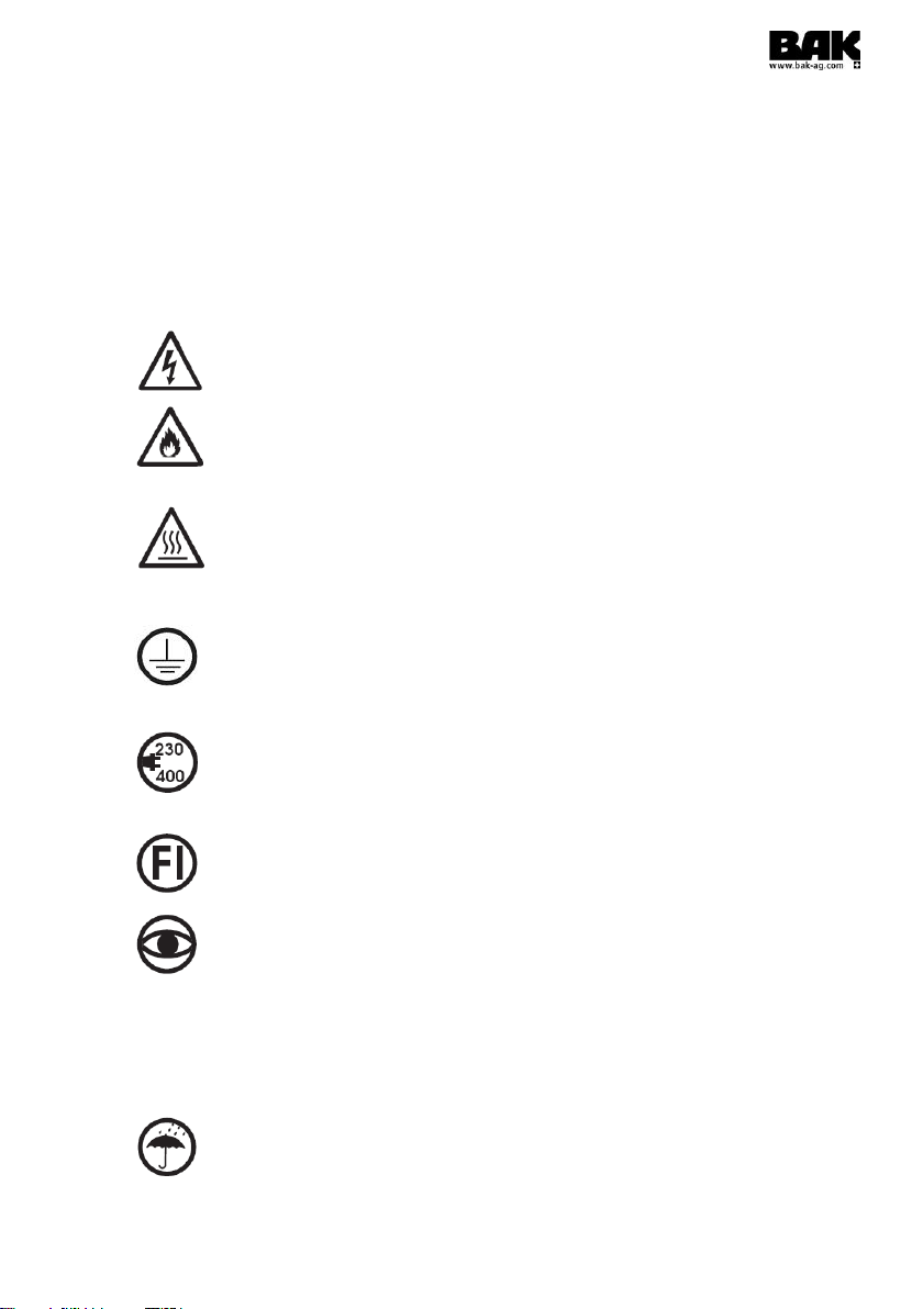
WARNING
If the power supply cable gets damaged, it has to be replaced by the manufactur-
er, its customer service or by a qualified person in order to avoid danger.
The device must not be used by personnel (including children) with limited phys-
ical, sensory or mental capabilities or lack of experience and/or knowledge, ex-
cept when supervised by a person who is responsible for their safety or when ad-
vised how to use the device by that person.
Children must be supervised in order to ensure that they do not play with the de-
vice.
Because of the enormous fire danger, the operating personnel must be specially
briefed and regularly instructed.
Fire can occur if the device is not used carefully.
Do not leave the device unobserved while it is in operation.
Demonstrate the necessary caution when operating the device near inflammable
materials. Do not operate on the same surface for longer periods of time.
A fire extinguisher must always be within reach in the work area.
The device must not be used in explosive atmospheres.
Heat may reach inflammable materials that are not visible.
There is a very significant risk of fire when the machine stops because of any dis-
turbance and the hot air device is still running (max. temperature of the air flow
650 °C). Therefore, special attention should be placed on the subsurface and the
material to be processed.
The welding machine must not be used on inflammable surfaces (e. g. wooden
roofs and floors)
The device bears the protection mark IP20 and must therefore be protected from
damp and rain.
When using the device on roofs and tables, it could fall down due to its automatic
drive system. In order to avoid a fall, necessary precautions must be taken.
The welding machine can be operated up to a maximum incline or slope of 30°.
Warning: Danger of poisoning! While processing thermoplastics or similar mate-
rial, gases occur which can be aggressive or poisonous. Avoid inhaling fumes
even if they seem to be harmless. Make sure the workplace is well ventilated or
wear respiratory protection.