Lumel P18D User manual

1
USER’S MANUAL
TEMPERATURE
AND HUMIDITY
TRANSDUCER
P18D TYPE

2

3
CONTENTS
1. APPLICATION . . . . . . . . . . . . . . . . . . . . . . . . . . . . . . . . . . . . . . . . . . . . . . . . . . . . . . . . . . . . . . . . . . . . . . . . . . . 5
2. TRANSDUCER SET . . . . . . . . . . . . . . . . . . . . . . . . . . . . . . . . . . . . . . . . . . . . . . . . . . . . . . . . . . . . . . . . . . 5
3. BASIC REQUIREMENTS, OPERATIONAL SAFETY. . . . . . . . . . . . . . . . 5
4. INSTALLATION .......................................................................... 6
4.1. Assembly ............................................................................................6
4.2. Electrical Connections ........................................................................7
5. SERVICING ................................................................................ 9
5.1. Messages after supply switching on ...................................................9
5.2. Description of P18D display ..............................................................10
5.3. Function of capacitive button ............................................................ 11
5.4. Function of the P18D transducer ...................................................... 11
5.4.1. Measured and calucated values ............................................. 12
5.4.2. Chosen of values for analog outputs.......................................13
5.4.3. Individual characteristic of analog outputs ..............................13
5.4.4. Default parameters..................................................................15
6. RS-485 interface...................................................................... 16
6.1. Serial interface connection................................................................16
6.2. Description of the Modbus Protocol Implementation.........................17
6.3. Description of the Modbus functions . . . . . . . . . . . . . . . . . . . . . . . . . . . . . . . . . . . . . . . . . . . . . . . . . 17
6.4. Register map.....................................................................................20
6.5. Register for write or readout..............................................................21
6.6. Register only for readout...................................................................24
6.7. Emergency restoration of default parameters ...................................26
7. ACCESSORIES . . . . . . . . . . . . . . . . . . . . . . . . . . . . . . . . . . . . . . . . . . . . . . . . . . . . . . . . . . . . . . . . . . . . . . . . 27
8. TECHNICAL DATA . . . . . . . . . . . . . . . . . . . . . . . . . . . . . . . . . . . . . . . . . . . . . . . . . . . . . . . . . . . . . . . . . . . 28
9. ORDERING CODES . . . . . . . . . . . . . . . . . . . . . . . . . . . . . . . . . . . . . . . . . . . . . . . . . . . . . . . . . . . . . . . . . 30
10. MAINTENANCE AND GUARANTEE ....................................... 31

4

5
1. APPLICATION
The P18D transducer is device destined for the continuous measure-
ment and conversion of relative humidity and ambient temperature into
a digital form and into a voltage or current standard signal. The trans-
ducer is fixed on a wall. The programming of the transducer is possible
by means of the RS-485 interface. The transducer configuration can
be carried out by the free LPCon program available on our website
www.lumel com.pl/en/.
Applied sensor shields enable the application of the P18D transducer in
various ambient conditions
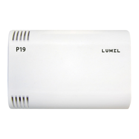
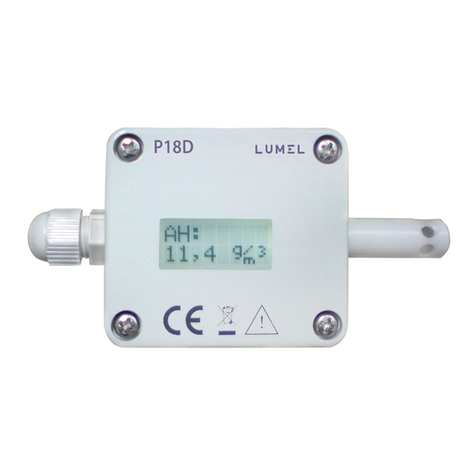
Fig.1. View of the P18D transducer.
2. TRANSDUCER SET
1. ransducer P18D..................... 1 pc
2. service manual........................ 1 pc
3. guarantee card........................ 1 pc
3. BASIC REQUIREMENTS, OPERATIONAL SAFETY
In the security scope, the transducer meets the requirements of the
EN 61010 -1 standard.
Remarks Concerning the Operator Safety:
1. General
· All operations concerning transport, installation, and commissioning as
well as maintenance must be carried out by qualified, skilled personnel

6
· Before switching the transducer on, one must check the correctness
ofconnections to the network.
· The device is destined to be installed and used in industrial electro-
magnetic environment conditions.
4. INSTALLATION
4.1. Assembly
The P18D transducer is designed to be mounted on a wall by means of
a screw connection or glue without the loss of IP65 tightness.
The transducer housing is made of a self-extinguishing plastics.
The transducer has screw connectors placed inside the transducer,
which enable the connection of external wires of 1 mm2cross-section.
Fig.2. Overall Dimensions of the P18D Transducer

7
Fig.3. Lay-out of Assembly Holes of the P18D Transducer
4.2. Electrical Connections
The P18D transducer has 8 connecting terminals to which there is
access after removing the cover of the transducer housing.
For electrical connections, one must use a round wire with external dia-
meter from 3.5 mm up to 6 mm.
Before the transducer assembly, one must remove the LCD display,
pass supplying wires through the packing. Twist the packing seal in
order to obtain the leaktightness. If the packing seal is not twisted,
we cannot ensure the required IP 65 leaktightness. After screwing the
wires to the terminal, the LCD dispaly should be put back.
Fig.4. Marking of Terminals for the Connection of External Signals

8
Transducer
without analog outputs
Transducer
with current outputs
Transducer
with voltage outputs
Fig. 5. Way of Electrical Signal Connection
To connect the input signals in an environment with high interference,
one must apply shielded wires. The shield must be connected to the
nearest PE point from the feeder side.
OUT1
( C)
OUT 2
(RH)
OUT 1
( C)
OUT 2
(RH)

9
5. SERVICING
The transmitter is equipped with a 8x2 characters display field with
backlight and one capacitive button located on the transmitter housing.
After connecting wires, closing and servicing the housing, and connecting
to the supply, the transducer is ready to work with manufacturer’s settings
(table 8).
The transducer can be programmed through the RS-485 interface.
One can program following parameters in the transducer:
-c o mmunication parameters
-a v eraging time of the measurement,
-i n dividual characteristics of analog outputs
(for executions with analog outputs).
There is the possibility to connect the transducer through another trans-
mission media, like: ETHERNET, USB, using LUMEL S.A.’s converters.
5.1. Messages after supply switching on
After connecting external signals and switching the supply on,
the transducer displays the type, the current software version, serial number
and set the communication parameters (address, baud rate and mode).
After about 5 seconds, the transducer automatically switches to the
mode in which it measures and converts into the analog output signal.
The transducer displays the measured value with the unit on the bottom
row of the display, on the top row of the display contains information about
the type of displayed value and pictograms: of transmission on RS-485
link, the mode of presentation of the measured value and the ratio of the
measured value read from the sensor.

10
Symbol Description
T: Type of displayed value in the lower line of LCD - temperature
RH: Type of displayed value in the lower line of LCD – relative humidity
DP: Type of displayed value in the lower line of LCD – dew point
AH: Type of displayed value in the lower line of LCD – absolute humidity
Readout ratio of measured value from the sensor
Automatic mode of measured values presentation – type of displayed
value is automatically switched every 3 seconds in following order:
temperature grealtive humidity gdew point gabsolute
humidity gtemperature ...
Indicator of data receive on the RS-485 interface
Indicator of data transmission on the RS-485 interface
5.2. Description of P18D display
Readout field in the transducer P18D is backlite character LCD. The
backlight is lit after turning on the power and the capacitive button is
pressed on the case. The backlight is turned off automatically after 30
seconds of inactivity time.
Fig.6 Description of P18D transducer readout field.
Indicator of measured value
readout from the sensor
Unit
Indicator of automatic presentation
of measured values
Indicator of transmission
on RS-485 interface
Measured value
Type
of measured value
The displayed symbols are shown in the table 1.
Tab le 1

11
5.4. Functions of the P18D transducer
l measurement of ambient temperature and relative humidity,
l calculation of chosen physical quantities (dew-point temperature,
absolute humidity),
l conversion of measured quantities into an output signal on the base
of the individual linear characteristic,
l memory storage of maximal and minimal values for each of the
measured and calculated value,
l programming of the measurement averaging time,
l RS-485 interface servicing in the MODBUS protocol, in RTU mode.
5.3. Functions of capacitive button
The P18D transducers have one capacitive button on the housing.
The position of the button is shown on the fig.7.
Fig.7 The position of the capacitive button of P18D transducer.
Functions of the capacitive button:
lswitch-on of the display backlight,
lchange of values presentation mode – hold down the button for about
2 seconds to switch from automatic to manual mode presentation
of the measurements or vice versa
lchange of measured value in the manual measurement presentation
mode - a brief touch of a button changes the displayed value.

12
where:
T gmeasured temperature [oC]
RH gmeasured relative humidity [%]
DP gtemperature of the dew-point [oC]
Pws gpressure of the satured water vapour
(water vapour pressure) [mbar]
AH gabsolute humidity [g/m3]
AH = 2.1668 ×Pws ×RH
100 ×(T+ 273.2)
DP = Tn
m- 1
log Pws ×RH
10000 ×A
)
Coefficients for the dew-point Table 2
T [oC] A m Tn
< 0 6.119866 7.926104 250.4138
0...50 6.1078 7.5 237.3
50...100 5.9987 7.3313 229.1
5.4.1. Measured and calculated values
Based on measured temperature and relative humidity the transducer
P18D calculates dew-point and absolute humidity from the following
relations.
DP g dew-point:
AH g absolute humidity:
(

13
5.4.3. Chosen of values for analog outputs
The P18D transducer in versions P18D-1XX and P18D-2XX has two
programmable analog outputs (current or voltage). By default, the first
analog output is set to present the value of the ambient temperature and
the second analog output is controlled by relative humidity value. Analog
outputs can respond to each of the measured or calculated value (T, RH,
DP, AH). The steering value of the analog outputs define the registers
respectively 4015 for the first output and 4016 for the second analog
output (Table 12).
5.4.4. Individual Characteristic of Analog Outputs
The P18D transducer in version with analog outputs enables the con-
version of measured quantities into an output signal on the strength of
individual linear characteristic of analog outputs. On the base of given
coordinates of two points by the user, the transducer determines (from
the system of equations) coefficients a and b of the individual charac-
teristic.
Y1Out = a ·X1In + b
Y2Out = a ·X2In + b
{
where:
X1 In and X2 In - measured value
Y1 Out i Y2 Out - expected value on the analog output.

14
The configuration of the individual characteristic of analog outputs
amounts to the introduction of suitable values X1, X2, Y1, Y2 in cor-
responding registers to them from the range 4007 – 4014 tab.3. Values
introduced in these registers must be integral values corresponding to
set point values multiplied by the value 100.
Example 1
Configuration of the individual characteristic of the first current analog
output (temperature):
The temperature conversion in the range -12.25oC÷ 77.75oCinto the
analogue current signal from the range 4.5 ÷ 18.5 mA is expected.
Table 3
Name Register address Value
X1temperature 4007 -1225
Y1current 4008 450
X2temperature 4009 7775
Y2current 4010 1850
Fig.8. Individual Characteristic of Analog outputs

15
5.4.5. Default parameters
Tab le 4 shows the default parameters of P18D transducer. These
settings can be restored using the RS-485 interface by writing into the
4020 register the value „1”.
Tab le 4
Parameter
description
Para-
meter
address
Default parameters
P18D-0XX P18D-1XX P18D-2XX
Address 4001 1
Baud rate 4002 9600
Mode 4003 RTU 8N2
Averaging time 4005 30 [s]
X1 for the first analog output 4007 0 -2000 -2000
Y1 for the first analog output 4008 0 400 0
X2 for the first analog output 4009 0 6000 6000
Y2 for the first analog output 4010 0 2000 1000
X1 for the second analog
output
4011 0 0 0
Y1 for the second analog
output
4012 0 400 0
X2 for the second analog
output
4013 0 10000 10000
Y2 for the second analog
output
4014 0 2000 1000
The first analog output
steering value
4015 0 0 0
The second analog output
steering value
4016 1 1 1
Special configuration 4019 8 8 8

16
6. RS-485 Interface
The P18D transducer has interface in RS-485 standard for communication
with computers and with other Master devices. On the interface has been
implemented MODBUS protocol.
6.1. Serial interface connection
Standard RS-485 port allows direct connection of up to 32 devices on a single
serial link with a length of 1200 m (at a baudrate of 9600 b/s). To connect more
devices it is necessary to use additional intermediate-separating devices
e.g. PD51 converterter/repeater of LUMEL S.A. production.
Derivation of the interface line is shown in the figure 3. To obtain a correct
transmission it is necessary to connect the A and B line parallel with their
counterparts in other devices. The connection of a shielded wires should
be performed. The wire shield should be connected to ground terminal
in the immediate vicinity of the transducer (one must connect the shield
to the terminal screen protection at one point).
To connect to the PC, the RS-485 interface card or the converter, e.g.
PD10 is required. How to connect your device is shown in figure 9.
Fig.9. Connection way of RS-485 interface.

17
6.2. Description of the MODBUS Protocol Implementation
The implemented protocol is in compliance with the PI-MBUS-300
Rev G Modicon Company specification. Following functions of the
MODBUS have been implemented in P18 transducers:
Set of parameters of the transducer serial link in the MODBUS
protocol:
- transducer address 1... 247
- baud rate 4800, 9600, 19200, 38400, 57600, 115200 bit/s
- work modes RTU: 8N2, 8E1, 8O1, 8N1
- information unit 8N2, 8E1, 8O1, 8N1
- maximal response time 500 ms
The configuration of serial link parameters consists on settlement
of baud rate, device address and protocoll.
Note: Each transducer connected to the communication network must have:
-unique address, different from other devices connected
to the network,
-the same baud rate and information unit type.
6.3. Description of Modbus functions
Functions of the Modbus protocol implemented in P18D transducer:
l03 (03h) – readout of register group
l 04 (04h) – readout of input register group
l 06 (06h) – write of an single register
l 16 (10h) – write of a register group
l 17 (11h) – identification of the slave device.

18
Reading-out n-registers (code 03h)
Example 1. Reading-out 2 registers starting with the register with the
float(32 bits) 1D4Dh (7501) address, (register values 25.68, 20.25.)
Request:
Device
address Function
Register address Number of registers Control sum
CRC
Hi Lo Hi Lo
01h 03h 1Dh 4Dh 00h 02h 52h 70h
Response:
Tab le 5
Device
ad-
dress
Fun-
ction
Num-
ber
bytes
Value from the register
1DB0 (7501)
Value from the register
1DB1 (7502) Control
sum
CRC
MSB LSB MSB LSB
01h 03h 08h 41h CDh 70h A4h 41h A2h 00h 00h 83h D0h
Tab le 6
Recording a single register (code 06h)
Example 2. Recording the value 78h (120) in the register FA1h (4001)
Request:
Device
address Function
Register address Register value Control sum
CRC
Hi Lo Hi Lo
01h 06h 0Fh A1h 00h 78h DBh 1Eh
Tab le 7
Response:
Device
address Function
Register address Register value Control sum
CRC
Hi Lo Hi Lo
01h 06h 0Fh A1h 00h 78h DBh 1Eh
Tab le 8

19
Tab le 7
Recording to n-registers (code 10h)
Example 3. Recording the value 78h (120) and value 4h (4) in the register
FA1h, FA2h (4001, 4002)
Request:
Response:
Tab le 9
De-
vice
ad-
dress
Fun-
ction
Register
address
Number of
register
Num-
ber of
bytes
Value for
the register
4001
Value
for the
register
4002
Control
sum
CRC
Hi Lo Hi Lo Hi Lo Hi Lo
01h 10h 0Fh A1h 00h 78h 04h 00h 78h 00 04 F8h 31h
Device
address Function
Register address Number of registers Control sum
CRC
Hi Lo Hi Lo
01h 10h 0Fh A1h 00h 02h 13h 3Eh
Tab le 10
Report identifying the device (code 11h)
Example 4. Device identification
Tab le 11
Device
address Function Control sum
CRC
01h 11h C0h 2Ch Tab le 12
Device
ad-
dress
Fun-
ction
Num-
ber of
bytes
Identi-
fier
De-
vice
status
Field depending on the
device software version
(e.g. 0.70)
Control
sum
CRC
01h 11h 0Eh CCh FFj
50h 31h 38h 44h 76h
2Eh 30h 2Eh 30h 34h
20h 00h
B1h 54h

20
6.4 Register Map
Table 13
Address
range
Value type Description
4000-4019 integer (16 bits) The value is located in the 16-bit register.
7000-7024 float (32 bits) The value is located i two successive 16-
bit registers. Registers contain the same
data as 32-bit registers from the area
7500-7512.
Registers are only for readout.
7500-7512 float (32 bits) The value is located in the 32-bit register.
Registers contain measured and
calculated data by the transducer.
Registers are only for readout.
In the P18D transducer the data is stored in 16- and 32-bit registers.
The process variables and parameters of the instrument are stored in
the address space of the registers in such way that they depend on the
variable type. The bits in the 16-bit registers are numbered from the least
significant to the most significant (b0 … b15). The 32-bit registers (4 Bytes)
contain floating-point numbers in IEEE-754 standard. Sequence of bytes:
B3 B2 B1 B0 – the most significant byte is sent as the first one.
Register map of the P30U transducer is presented below.
Note: All the addresses given are physical addresses. In some computer
programs logical addressing is applied, then the addresses should be
increased by 1.
Other manuals for P18D
1
Table of contents
Other Lumel Transducer manuals
Popular Transducer manuals by other brands

Phoenix Contact
Phoenix Contact MCR-F-UI-DC manual

S+S Regeltechnik
S+S Regeltechnik THERMASGARD ALTM 2-VA Operating Instructions, Mounting & Installation

Wassp
Wassp WMB-X230 installation manual

Humminbird
Humminbird ICE HELIX Series installation guide

CARLO GAVAZZI
CARLO GAVAZZI PQT-90 instruction manual

ADInstruments
ADInstruments MLT844 quick start guide