Baker ChemoSHIELD CS500 User manual

P. O. Drawer E / 161 Gatehouse Road / Sanford, Maine 04073 / USA
800-992-2537 / 207-324-8773 / Fax: 207-324-3869 / bakerco@bakerco.com / bakerco.com
OPERATOR'S MANUAL
Negative Pressure Isolator
MODEL
CS500
Revision
Date
Description
H 5/19/15 UPDATED BRANDING.
This manual includes information for installation, operation, maintenance and spare parts. We recommend that it be
kept near the cabinet for ready reference.
351D700 Rev H i

P. O. Drawer E / 161 Gatehouse Road / Sanford, Maine 04073 / USA
800-992-2537 / 207-324-8773 / Fax: 207-324-3869 / bakerco@bakerco.com / bakerco.com
INTRODUCTION AND WELCOME
It is a pleasure to welcome you to the growing number of customers who own and operate Baker
cabinets and glove boxes. As the inventors of the laminar flow biological safety cabinet and the
leaders in the field, Baker people take special pride in providing a cabinet that is designed for
maximum performance.
Your new ChemoSHIELD® cabinet includes many unique features which are included to give
you superior performance, simpler maintenance and lower life cycle cost. Your ChemoSHIELD®
cabinet operates under negative pressure and is designed for protection of product, personnel and
the environment. You will find your ChemoSHIELD® cabinet suitable for sterile compounding of
hazardous or potent pharmaceutical compounds, chemotherapy agents and IV admixtures that can
be harmful to laboratory personnel.
In addition to the high quality you expect from all Baker equipment, this model has been
ergonomically designed to provide the lab user with many exciting design features. The
ergonomic design will help prevent repetitive motion injury, reduce fatigue and lab accidents
and enhance productivity.
The adequacy of a cabinet for user safety should be determined on-site by an industrial
hygienist, safety officer or other qualified person. Remember that you, the owner and user, are
ultimately responsible and that you use your cabinet at your own risk.
We recommend that this manual, along with the factory test report, be kept near the cabinet for
convenient reference by operators and qualified maintenance personnel. If you have any
questions about the use or care of your new ChemoSHIELD® cabinet, please do not hesitate to
contact our Customer Service Department at 800-992-2537 for assistance or e-mail us at
bakerco@bakerco.com.
Sincerely,
David Eagleson
President
The Baker Company, Inc.
P.O. Drawer E, Sanford, Maine 04073 (207) 324-8773 1-800-992-2537 FAX (207) 324-3869
Visit our website at www.bakerco.com
351D700 Rev H ii

P. O. Drawer E / 161 Gatehouse Road / Sanford, Maine 04073 / USA
800-992-2537 / 207-324-8773 / Fax: 207-324-3869 / bakerco@bakerco.com / bakerco.com
TABLE OF CONTENTS
I - FUNCTION AND DESCRIPTION OF THE CHEMOSHIELD
.....................................................................1
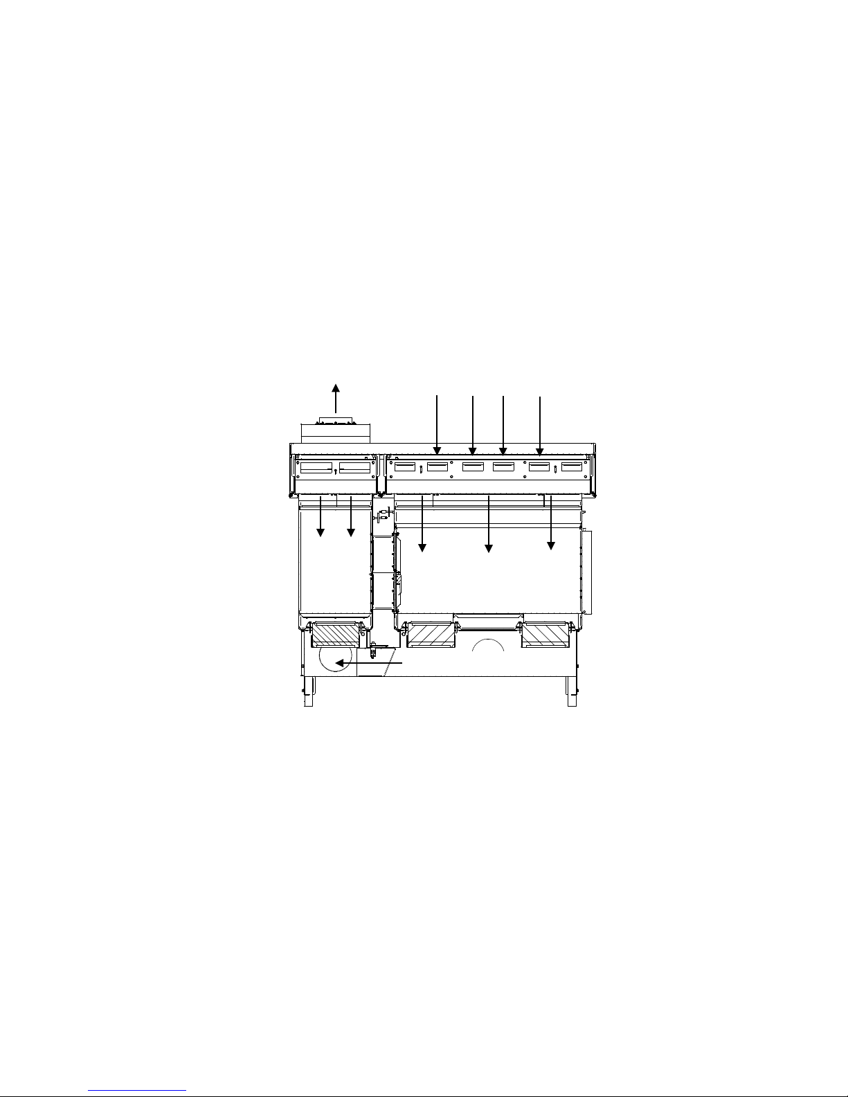
CHEMOSHIELD AIRFLOW AND BASE FEATURES .......................................................................................................1
Fig. 1: Airflow Inside Cabinet..............................................................................................................................1
CABINET PRESSURE AREAS ........................................................................................................................................2
ACCESS TO THE WORK CHAMBER ..............................................................................................................................2
DESIGN DETAILS.........................................................................................................................................................2
Performance assurance.........................................................................................................................................2
Building exhaust requirement................................................................................................................................3
Chamber walls and tunnel construction................................................................................................................3
All-metal plenums..................................................................................................................................................3
Stainless steel work surfaces..................................................................................................................................3
Cabinet exterior panels..........................................................................................................................................3
Tested HEPA filters ...............................................................................................................................................3
Viewscreens...........................................................................................................................................................3
Work chamber and pass-through lighting.............................................................................................................3
Chamber base pan construction and clean ability ................................................................................................3
Cabinet air balance adjustments...........................................................................................................................3
Easy filter access ...................................................................................................................................................4
Telescoping stand..................................................................................................................................................4
Mechanical interlock between pass-through door & inter-chamber door ............................................................4
Pressure monitoring of chambers..........................................................................................................................4
Airflow monitor – AFM .........................................................................................................................................4
Auxiliary switch (Optional) ...................................................................................................................................4
Electrical duplex....................................................................................................................................................5
Lift system (Optional) ............................................................................................................................................5
SPECIFICATIONS FOR CHEMOSHIELD®-MODEL CS500............................................................................................5
Weight....................................................................................................................................................................5
Electrical Specifications........................................................................................................................................5
Environmental Conditions.....................................................................................................................................6
Symbols and Terminology .....................................................................................................................................6
II - PREPARING THE CHEMOSHIELD® FOR USE.............................................................................................7
CHECKING THE CABINET UPON ARRIVAL...................................................................................................................7
THE USES OF A CHEMOSHIELD®CABINET................................................................................................................7
LOCATION WITHIN THE LABORATORY........................................................................................................................7
INSTALLING THE CABINET ..........................................................................................................................................7
FINAL CONNECTIONS AND TESTS................................................................................................................................8
III - PROPER CABINET USE...................................................................................................................................9
OPERATOR CONTROLS................................................................................................................................................9
START-UP PROCEDURE ...............................................................................................................................................9
LOADING MATERIALS AND EQUIPMENT....................................................................................................................10
RECOMMENDED WORK TECHNIQUES .......................................................................................................................10
UNLOADING AND WIPE DOWN ..................................................................................................................................10
REACTING TO SPILLS ................................................................................................................................................10
DECONTAMINATION..................................................................................................................................................10
CLEANING AND DISINFECTING STAINLESS STEEL......................................................................................................11
Simple Cleaning...................................................................................................................................................11
Disinfection..........................................................................................................................................................11
351D700 Rev H iii

P. O. Drawer E / 161 Gatehouse Road / Sanford, Maine 04073 / USA
800-992-2537 / 207-324-8773 / Fax: 207-324-3869 / bakerco@bakerco.com / bakerco.com
ABOUT THE HEPA FILTERS......................................................................................................................................12
REMINDERS ..............................................................................................................................................................12
APPENDIX.................................................................................................................................................................13
REPLACEMENT PARTS LIST.......................................................................................................................................14
AIRFLOW MONITOR OPERATION &CALIBRATION.....................................................................................................15
WARRANTY.............................................................................................................................................................16
! WARNING !
The agents used and/or work performed in this cabinet
may be hazardous to your health and to the health of
others. The cabinet must be used properly. You must read
the operator’s manual before using.
351D700 Rev H iv

I - FUNCTION AND DESCRIPTION OF THE ChemoSHIELD
The ChemoSHIELD® is a negative pressure isolator offering product, personnel & environment protection
from hazardous or potent pharmaceutical compounds and chemotherapy agents. It features vertical laminar
airflow and a closed front viewscreen. Other uses for the cabinet include formulation, mixing of hazardous
non-explosive chemical compounds and other applications that require Class 100 (ISO Class 5) air.
ChemoSHIELD Airflow and Base Features
The ChemoSHIELD®cabinet is designed to provide vertical laminar airflow within the work chamber
(See Fig. 1). The stainless steel metal diffuser just below the downflow HEPA filter creates gentle laminar
airflow over the work zone and an air curtain at the viewscreen. The air pressure is negative in the work
zone to insure maximum personnel protection while the sealed work chamber and HEPA filtered airflow
provides product protection.
Fig. 1: Airflow Inside Cabinet
(-) = Negative Pressure
The pass-through chamber allows operators to introduce or remove items from the main work chamber
while maintaining the internal aseptic conditions. The stainless steel metal diffuser just below the downflow
HEPA filter creates laminar airflow in the chamber and air curtains at the viewscreen and tunnel connecting
the two chambers. The air pressure is negative to insure maximum personnel protection.
Airflow within the tunnel connecting the two chambers is slightly turbulent due to the pass-through air
curtain. This helps purge the tunnel.
Airflow within the work and pass-through chambers is pulled through exhaust HEPA filters located under
the work surfaces into a common exhaust plenum. The air is then exhausted out of the cabinet through the
building exhaust system.
Exhaust Air
Room Air
Intake
(-) HEPA Filtered Exhaust Air
(-) HEPA
Filtered
Air
(-) HEPA Filtered Air
Work Chamber
351D700 Rev G 1

It is recommended that the pass-through chamber operate at a higher negative pressure than the work
chamber. This will provide the most favorable condition for both product and personnel protection.
The pass-through chamber has an external access door with gloveport. An inter-chamber door is located
inside the work chamber. These doors have a mechanical interlock system to keep both doors from being
open at the same time.
The work chamber viewscreen has key lock latches and two gloveports equipped with gloves to provide a
physical barrier between the technician and the product. The viewscreen is hinged along the top and may be
fully opened for loading or unloading.
! CAUTION !
The viewscreen should never be opened until after the work chamber has been properly
cleaned and decontaminated.
The Baker Company has included ergonomic enhancements into the design of the ChemoSHIELD®for
improved operator comfort and safety. A 10°sloped front feature and adjustable stand have been
incorporated into the design to improve ergonomics so the operator can use the cabinet comfortably either
standing or sitting without sacrificing safety.
Cabinet Pressure Areas
One of the many features that sets the ChemoSHIELD®unit apart from other cabinets is the interaction of
its pressure areas. The whole cabinet is under negative pressure when operating. The pass-through chamber
operates at a more negative pressure than the adjacent work chamber. This allows air to flow into the pass-
through chamber when the inter-chamber door is open to insure product protection in the work chamber.
When the pass-through access door is opened room air is pulled into the chamber thus helping personnel
protection.
The ChemoSHIELD®provides better than Class 100 (ISO Class 5) air cleanliness conditions within the
enclosure.
Access to the Work Chamber
For easy entry of apparatus into the work chamber, ChemoSHIELD®has a top hinged viewscreen. Its 3/8
-inch shatterproof polycarbonate viewscreen allows excellent visibility, and can be opened fully to permit
placement of large items in the work area.
! CAUTION !
The viewscreen should never be opened until after the work chamber has been properly
cleaned and decontaminated.
While in operation the pass-through is used to bring items in and out of the cabinet.
Design Details
Performance assurance
Meticulous care in manufacturing is followed by physical and performance tests prior to shipment of your
cabinet. In addition, a complete factory test report on your cabinet is included at the rear of this manual.
351D700 Rev G 2

Building exhaust requirement
Your ChemoSHIELD®cabinet has an 8” exhaust collar and requires the building exhaust connection to
handle 1.8” WC at 310 CFM.
Chamber walls and tunnel construction
The chamber walls and tunnel of your ChemoSHIELD®are constructed of 16 gauge, type 316 stainless
steel. The easy-to-clean 7/16-inch radiused (rounded) corners prevent buildup of contaminants and resist
corrosion. The chambers are designed to be leak tight to 2” WC.
All-metal plenums
The plenums of your ChemoSHIELD®unit have been constructed entirely of metal in order to provide
strength, durability, air-tightness and resistance to deterioration.
Stainless steel work surfaces
The work surfaces are constructed of corrosion-resistant 16-gauge, type 316 stainless steel. They have a #4
satin finish that diminishes light reflection.
The work chamber has a three (3) piece flat work surface and the pass-through chamber has a two (2)
piece flat work surface. The work surfaces are removable so that you can access the exhaust filters.
Cabinet exterior panels
External panel construction is of 16-gauge cold-rolled steel protected by a smooth white baked enamel
finish.
Tested HEPA filters
The filters in the ChemoSHIELD®are scan-tested HEPA filters. They are 99.99% effective on particles of
0.3 micron in size. Each filter is scan-tested after installation to assure that there are no leaks >.01% of
upstream concentration.
Viewscreens
Your ChemoSHIELD®has 3/8-inch shatterproof, clear polycarbonate in both the pass-through door and
the work chamber viewscreen.
Work chamber and pass-through lighting
The lighting system produces at the work surface of the work chamber an average of 50 foot-candles of
illumination and 45 foot-candles at the work surface of the pass-through chamber. Two fluorescent lamps
are externally mounted to minimize heat buildup. The cabinet uses one F39T5/HO fluorescent lamp for the
work chamber and one FT36W-2G11-41 fluorescent lamp for the pass-through chamber.
Chamber base pan construction and clean ability
The base pan is constructed of 16-gauge, type 316 stainless steel with 7/16” radius in all corners to
facilitate cleaning. The work surfaces can be repositioned for cleaning of the chamber pans.
Cabinet air balance adjustments
Only a technician with proper training and equipment should perform air balancing. (See Section IV, "On-
Site Checks and Maintenance Procedures.")
351D700 Rev G 3

•Each chamber has an inlet plenum with manual damper to control airflow and static pressure within the
chamber.
•A single damper located in the base of the cabinet is used to adjust the pressure balance between the two
chambers.
Easy filter access
For convenience and ease of service, the downflow HEPA filters are installed and removed through the top
front of the cabinet. The exhaust HEPA filters are designed for bagging inside of the cabinet and removal
through the pass through. Only a qualified technician should service the filters.
Telescoping stand
The cabinet stand provides the following range of heights:
Knee
Space
Height
Work
Surface
Height
Overall
Height
Minimum Setting
32”
36”
84”
Maximum Setting
41”
45”
93”
Mechanical interlock between pass-through door & inter-chamber door
A mechanical interlock is provided that prevents both doors being open at the same time.
Pressure monitoring of chambers
Two pressure gauges are provided to monitor the negative pressure levels inside the pass-through and
work chambers. The gauges are comparing chamber pressure to the room pressure.
Airflow monitor – AFM
The AFM is an audible and visual alarm system consisting of solid state flow measuring and alarm
circuitry in a small enclosure. The AFM has a hot wire anemometer probe that is installed in the cabinet
exhaust duct. The measuring circuit and probe can be replaced separately.
The AFM is equipped with two relays. The yellow “Warning” level, which can be connected to a remote
alarm device, and the red “Alarm” level that is connected to the cabinet Control Board to shut down the
cabinet blower if the exhaust airflow is not adequate (NCB / SG-TX ONLY). The AFM alarm set point is
established at our factory but will need to be confirmed after it is installed in the field. The AFM visual
indicators are Green (Power), Yellow (Warning), Blue (Mute), and Red (Alarm) LEDs. Further information
on AFM operation can be found in the Appendix of this manual
Auxiliary switch (Optional)
An auxiliary switch located on the electrical panel rated at 125-277 VAC, 15A is available for wiring to a
fan/blower for the building exhaust system so that it can be turned on/off from the cabinet, if required. Refer
to pages 32 and 33 for the junction box location and wiring schematic.
351D700 Rev G 4

Electrical duplex
Two GFI protected duplex outlets with weather-proof covers are located in the rear wall of the work
chamber. These outlets are protected by a self-resetting circuit breaker to allow 10A maximum total to all
outlets. A rocker switch rated at 125VAC, 15A is located on the electrical panel for turning the outlets
on/off.
Lift system (Optional)
An electric motor driven hydraulic lift system is available for adjusting the height of the cabinet. It is rated
at 115VAC, 2A (Intermittent Duty, Max 1.2 min. on/12 min off). The lift has a travel range of
approximately 11 3/8”.
Specifications for ChemoSHIELD® - Model CS500
Weight
Cabinet on Standard Tube Leg Stand: 570 pounds
Cabinet on Hydraulic Stand: 600 pounds
Shipping weight: Add 90 pounds to weights above
Electrical Specifications
All electrical wiring should comply with the National Electrical Code and any applicable
Local Electrical Code at the site of installation.
The cabinet is to be powered by a 115 V AC, 15A, 60 Hertz, Single Phase dedicated circuit. This circuit
should be protected by a 15A circuit breaker or fuse.
Typical Current for the Standard unit: 1.4A
Duplex receptacles: 10A
Optional Hydraulic Lift: 2A (Intermittent Duty, Max 1.2 min. on/12 min off)
The cabinet is furnished with one 9 FT power cord with 15A, NEMA 5-15P type plug.
The power cord is the Main Disconnect device for the cabinet. The cabinet should be
positioned in a manner that allows easy access to the power cord connection to the electrical
utility.
The cabinet is internally protected with a 250 VAC, 15A time delay fuse, Buss MDA-15 or equivalent.
The cabinet has 2 GFCI protected, 115V AC, Duplex outlets. The outlets are controlled using a rocker
switch mounted in the front panel. The outlets on this circuit are protected by a 10A self-resetting circuit
breaker.
The cabinet may be provided with an optional Auxiliary Switch that can be wired to control an external
building exhaust fan/blower or other device. The switch rating is 125V- 277V AC, 15A.
351D700 Rev G 5

The optional Auxiliary Switch circuit introduces a second power source to the cabinet. All
power sources must be disconnected before the cabinet is electrically safe. Use proper
Lockout/Tagout procedures.
The cabinet may be provided with an optional lift system rated at 115 VAC, 2A.
(Intermittent Duty, Max 1.2 min. on/12 min off).
Environmental Conditions
The cabinet is designed for use under the following conditions:
•Indoor use
•Altitudes up to 2000 meters
•Maximum relative humidity 80%for temperatures up to 31°C decreasing linearly to 50%relative humidity at
40°C.
•Main supply voltage 105 to 125Volts AC
•Transient overvoltages according to Installation Categories (OVERVOLTAGE CATAGORIES) II
per UL/IEC61010-1, 2nd Edition
•Pollution Degree 2
Symbols and Terminology
Protective Earth: Any terminal intended for connection to external protective conductor for
protection against electric shock in case of a fault.
General Caution: Refer to instruction manual for information regarding personnel and
environment protection.
!
351D700 Rev G 6

II - PREPARING THE ChemoSHIELD®FOR USE
Checking the Cabinet Upon Arrival
Upon receipt of your new ChemoSHIELD® cabinet, first inspect the exterior of the crate, box and/or skid.
If there is any visible damage, that fact should be noted on the receiving slip and immediately reported to the
delivering carrier.
Next, remove the packing material and inspect the cabinet itself. Remove the cabinet from the skid with a
forklift or other available equipment. If any concealed damage is found it should be reported to the
delivering carrier. A claim for restitution should be filed within 15 days.
The Uses of a ChemoSHIELD®Cabinet
The ChemoSHIELD® is a negative pressure isolator offering product, personnel & environment protection
from hazardous or potent pharmaceutical compounds and chemotherapy agents. It features vertical laminar
airflow and a closed front viewscreen. Other uses for the cabinet include formulation, mixing of hazardous
non-explosive chemical compounds and other applications that require Class 100 air (ISO Class 5).
! CAUTION !
Explosive or flammable substances should never be used in this cabinet.
Location Within the Laboratory
Position the ChemoSHIELD® so the pass- through chamber end is 15” away from any wall or obstruction.
This clearance is needed for the pass-through access door to swing open freely. The work chamber end and
rear of the cabinet requires minimal space. The front of the cabinet requires 28” of clearance for the work
chamber viewscreen to swing open freely.
The ChemoSHIELD® is a negative pressure isolator and requires a room exhaust system capable of
handling 1.8” WC at 310 CFM.
Installing the Cabinet
Installation of this cabinet should be carried out in accordance with appropriate OSHA regulations and
those of other regulatory agencies having jurisdiction.
1. Remove the protective container from around the cabinet.
2. Remove the strapping that holds the cabinet to the pallet. Lift the cabinet off the pallet, place it on a
dolly and move it to the intended location.
3. Lift the cabinet off the dolly and extend the legs to the desired position.
4. Slide the cabinet into its desired position within the room. Level the cabinet using the leg levelers.
5. Remove all tape used to secure cabinet components during shipping.
351D700 Rev G 7

Final Connections and Tests
1. A 15-amp power cord with a NEMA 5-15P plug is furnished with the ChemoSHIELD®. It should be
plugged into an appropriate 115 Volt AC, 15 Amp, 60 Hz utility outlet.
2. Turn on the fluorescent light and make sure the bulbs are lighted.
3. Check to see if the AFM is being powered.
4. Turn on the duplex power switch and confirm that power is going to each duplex.
5. Push the optional cabinet lift system control switch and run the lift up, then down.
NOTE: Make sure you have enough clearance between the top of the cabinet and the ceiling
before conducting the test.
6. Thoroughly clean the interior of the cabinet.
7. If required by the user, the cabinet can be given a pressure decay test per the American Glovebox Society
guidelines. (Reference the cabinet factory test report for information on the test criteria used)
NOTE: This test should be performed before the cabinet is connected to the building exhaust
system (See Fig. 4 in the appendix).
8. Connect the cabinet to the building exhaust system.
9. Although all cabinets are carefully tested at the factory, it is advisable that certain other checks are made
on-site by a qualified technician after installation. These include testing the filters for leaks, checking
the air balance of the cabinet and using a particle counter to verify air cleanliness inside the chambers. A
description of these tests can be found in Section IV, "On-site Checks and Maintenance."
10. It is recommended that all personnel who will be using the cabinet study this Operator's Manual to learn
how to use the cabinet most effectively. For additional start up and use procedures, please turn to
Section III, "Proper Cabinet Use."
351D700 Rev G 8

III - PROPER CABINET USE
Your ChemoSHIELD® is a valuable supplement to good aseptic technique, but is not a replacement for it.
If the cabinet is not understood and operated correctly as defined in this manual it will not
provide an adequate protective barrier for personnel or product.
All activities that are to be performed in your cabinet should first be approved by a competent
professional, such as an industrial hygienist or safety officer, to make sure that the cabinet is appropriate for
the work it will be required to do. This person should monitor the cabinet and its operating personnel at
regular intervals to see that it is being used correctly.
In order to keep the interior workspace clean and free of particulates, Your ChemoSHIELD® is designed
for continuous operation. Therefore it is recommended that the exhaust system be left on at all times.
Operator Controls
The operator controls and indicators are arranged on the front electrical panel of the cabinet.
1 - Light On/Off Switch
This switch controls operation of the fluorescent lights. The indicator light on the switch will
illuminate when the fluorescent lights are turned on.
2 - Auxiliary (“AUX”) Switch (Optional)
This switch is available for wiring to a building exhaust system fan/blower so that it can be turned
on/off from the cabinet, if required. The indicator light on the switch will illuminate when the auxiliary
switch is turned on.
3 - Duplex Outlet Switch
This switch is used for turning on/off the duplex outlets. The indicator light on the switch will
illuminate when the outlets are turned on.
4 - Hydraulic Lift (Optional)
The Hydraulic Lift has a momentary rocker switch to control the UP and DOWN motion of the lift.
The maximum and minimum limits of travel are controlled by limit switches on the lift system.
Start-up Procedure
1. If the cabinet has not been left running continuously turn on the building exhaust fan. Check the
readings on the mag gauges. They should be consistent with the last time the cabinet was on.
2. Turn on the fluorescent lights.
3. Verify that work area and pass through grills are free from any obstructions.
4. Inspect gloves & sleeves for holes.
5. Latch the work chamber viewscreen and pass-through access door in the closed position.
This cabinet should never be operated with the work chamber viewscreen open or unlatched
Note: The latches have key locks
351D700 Rev G 9

6. Allow the cabinet to run at least 3 minutes so that the chambers can purge with HEPA filtered air.
7. Wipe down the interior area of the cabinet with a surface disinfectant.
Note: Some disinfectants, such as bleach or iodine, may corrode or stain the steel surfaces. If this
happens, thoroughly clean the surfaces afterward with a detergent and rinse with sterile water to
prevent corrosion.
Loading Materials and Equipment
1. Place all materials and equipment needed in the cabinet via the pass-through door. After closing the door
wait 1 minute before opening the inter-chamber door. This will allow the pass-through chamber and
tunnel enough time to purge with HEPA filtered air. Important: Make sure to disinfect items before
moving them from the pass-through chamber to the work chamber.
2. Avoid blocking front and rear grills.
3. Arrange materials to minimize movement within the cabinet.
4. Leave the inter-chamber door closed while working in the work chamber.
Recommended Work Techniques
1. Perform all work on or over the solid work surface. Avoid working on the grills.
2. Keep the viewscreen closed and latches locked.
3. Limit opening of pass-through and inter-chamber doors when moving materials or equipment.
4. Make sure to wait 1 minute anytime the pass-through door has been open and closed to allow the
chamber and tunnel to purge with HEPA filtered air.
Unloading and Wipe down
1. Close the inter-chamber door before opening the pass-through door when unloading materials and
equipment.
2. Wipe down the work and pass-through chambers with disinfectant before opening the pass-through
door. Never use the cabinet to store supplies or laboratory equipment.
3. We recommend that the cabinet be left running continuously to ensure cleanliness. If the user elects to
turn the building exhaust fan off at the end of a work session, the work chamber viewscreen and pass-
through door should be closed completely and latched.
Reacting to Spills
Spills should be cleaned immediately to prevent cross contamination to the work and to avoid any damage
to the stainless steel surfaces.
It is recommended that the researcher, in coordination with their consulting safety professional, have a
written plan available in case of an accidental exposure or spill. The safety plan should include all of the
emergency procedures to be followed in the event of an accident. All employees who use the cabinet should
be familiar with the safety plan.
Decontamination
It is recommended that the researcher, in coordination with their consulting safety professional, have a
written decontamination plan available based on what the cabinet is being used for. All employees who use
the cabinet should be trained on how to perform the decontamination procedure.
351D700 Rev G 10

Cleaning and Disinfecting Stainless Steel
Simple Cleaning
IMPORTANT
Do not use steel wool or steel pads when cleaning stainless steel.
Dirt deposits on stainless steel (dust, dirt and finger marks) can easily be removed. Usually, warm water,
with or without detergent, is sufficient. If this does not remove the deposits, mild, non-abrasive household
cleaners can be used with warm water and bristle brushes, sponges or clean cloths.
Iron rust discoloration can be treated by rubbing the surface with a solution of 15% to 20% by volume of
Nitric Acid and water and letting it stand for one to two minutes to loosen the rust.
Disinfection
The purpose of disinfection is to destroy particular organisms that could pose a potential hazard to humans
or compromise the integrity of the experiment. It is important to use a suitable disinfectant in the
concentration appropriate to the organism being killed. Standard disinfectants include: Hypochloride
(chlorine bleach), Iodophor-Detergent, Ethanol, Phenol and Alcohol.
IMPORTANT
Disinfection and cleaning should always be followed by rinsing in sterile hot water and wiping the
surface completely dry.
Disinfect the work surface before and after every procedure.
1. Disinfect surfaces of all equipment used.
2. Remove all items from the inside of the cabinet.
3. Place all items that may have come in contact with the agent(s), such as used pipettes, in a plastic
bag or other suitable container.
4. Disinfect the entire inside surface of the cabinet.
For additional information on cleaning and disinfecting stainless steel, please refer to: “Decontamination,
Sterilization, Disinfection, and Antisepsis”, Vesley, Donald and Lauer, James L., Laboratory Safety
Principles and Practices, Second Edition, 1995, Fleming, D.O., Richardson, J.H., Tulis, J.J. and Vesley, D.,
editors, ASM Press, Washington, D.C., pp. 219-237; and Biosafety Reference Manual, Second Edition,
1995, Heinsohn, P.A., Jacobs, R.R. and Concoby, B.A., editors, AIHA Publications, pp.101-110.
351D700 Rev G 11

About the HEPA Filters
The High Efficiency Particulate Air (HEPA) filter is one of the essential components of a clean air cabinet.
It is the shield, which stands between the product and the environment.
The HEPA filter consists of a continuous sheet of glass fibers pleated and mounted in a rigid frame. It is
very delicate and the filter media should never be touched.
Proven efficiency in all HEPA filters used in Baker cabinets are 99.99% for particles 0.3 microns in
diameter. The 0.3 micron particle is used as the basis for filter definition because theoretical studies have
shown that filtration efficiency should be at a minimum for particles of this diameter, with efficiency
increasing for particles either larger or smaller. Experiments with various viruses and microbial agents have
proven the effectiveness of HEPA filters. (Contact The Baker Company for more information).
It must be pointed out that the HEPA filter is not intended to filter gasses or vapors, nor are they 100%
efficient on particulates.
The room and cabinet particulate levels along with the capacity of the building exhaust fan determines the
life of a filter. Under most laboratory conditions, you should expect a long filter life. However, misuse or a
heavy particulate load within the cabinet will shorten any filter's life.
Reminders
After many years of seeing our equipment used and misused, we have made up this list of suggestions:
•Store equipment and supplies outside of the cabinet.
•Always leave the building exhaust fan on.
•Keep the work chamber viewscreen closed and latches locked.
•Avoid using an open flame within the cabinet unless it has been specifically approved by a safety
professional.
•Always keep the air grilles clear and unobstructed.
•Toxic, explosive or flammable substances should not be used in the ChemoSHIELD®.
•Don’t operate the cabinet above the recommended manufacturer exhaust flow rate.
351D700 Rev G 12

Appendix
351D700 Rev G 13

Replacement Parts List
Mechanical Items Baker Part Number
Mag. Guage 20773
Electrical panel assembly 338A505
Gas Cylinder 41041
Ball socket for gas spring 40902
Inter-Chamber Door 338A604
Pass-Through Door Assembly 338A306
Work Chamber Viewscreen
Assembly 338A305
Connector, Gloveport Sleeve 39608
Filter, HEPA, 18” x 35” x 3” 351A103
Filter, HEPA, 18” x 20” x 3” 338A104
Filter, HEPA, 11.5” x 13” x 6” 39797
Filter, HEPA, 9” x 13” x 6” 40817
Replacement Filters kit for
complete cabinet 351G000
Latch, Inter-Chamber Door 40114
Latch, Pass-Through Door 40114
Latch, Work Chamber Viewscreen 40881
Nitrile Glove, SM/MED/L/EXL 40699 / 40700 / 40701 / 40703
Electrical Items Baker Part Number
Fluorescent Lamp – Work
Chamber 41387
Lamp Holder – Plunger End 41438
Lamp Holder – Fixed End 41439
Ballast 41385
Fluorescent Lamp – Pass through 38682
Lamp Holder – Pass through 35072
Rocker Switch - Lights 15826
Rocker Switch - Aux 15826
Rocker Switch – Duplex outlets 15826
Terminal Block 39195
351D700 Rev G 14

Airflow Monitor Operation & Calibration
Power up:
•When power is applied to the AFM, the Green (Power) LED will flash, until reset by the “Alarm
Reset” button. This acts as an indicator of an unattended power outage.
•The AFM will be in alarm state for 20 seconds at initial power turn-on
•The beeper is disabled at power turn-on, for 20 seconds
•The blue, red and yellow LEDS light solid, for 20 Seconds
Normal Operation:
•Yellow & Red LEDs are NOT ON, no alarm activated.
Warning:
•There is a 6 second delay to the “WARNING” condition, at which time the “FLOW” relay contact
will change, and the audible alarm and yellow LED will begin flashing. When normal airflow
resumes, the “FLOW” relay will return to normal and the beeper will stop. The yellow LED will
remain latched ON solid, until reset with the Alarm Reset button.
Alarm:
•The delay to the “ALARM” condition is limited by the probe response, typically 4 seconds. When
the “ALARM” condition is detected, the “BLOWER” relay will change to “ALARM” condition.
At this time, the audible alarm will pulse at a faster rate and the red LED will begin flashing. When
normal airflow is resumed, the “BLOWER” relay will change states and will have a slower single
audible alarm. The red LED will be latched ON solid, until reset with the Alarm Reset button.
No Probe:
•Red and Yellow LEDs flash and there will be an audible alarm.
Mute:
•The audible alarm can be muted (disabled) for a fixed time (5 minutes) by pressing the “MUTE”
button on the front panel. This button initiates a 5 minute timer. While the unit is muted the blue
LED will flash. If 4 minutes into the mute, the button is pressed again, the timer restarts at 5
minutes.
•A return to a no Warning/Alarm condition will reset the Mute and the blue LED will stop flashing.
•A new alarm will enable the beeper. If the beeper is muted for a “Warning” condition, it will be
enabled again if an “ALARM” occurs.
•A special Absolute Mute can be activated by pressing both the “MUTE” and “RESET” buttons.
During Absolute Mute the blue LED is ON solid. No transitions into or out of alarm will activate
beeper, or reset mute. Absolute mute lasts the full 5 minutes.
Reset:
•After “WARNING” and “ALARM” conditions occur and recover, LEDs are latched solid until the
unit is reset, with the RESET button.
•Resetting before conditions clear, will result in restarting of “WARNING/ALARM visual and
audible indications
351D700 Rev G 15

Warranty
The Baker Company, Inc., expressly represents and warrants all goods (a) to be as specified (and described)
in The Baker Company catalogues and literature, and (b) to be free under normal use, service and testing (all
as described in The Baker Company, Inc., catalogues and literature) from defects in material and
workmanship from a period of thirty-six (36) months from the invoice date [US/Canada only] and Twelve
(12) month warranty for international.
The exclusive remedy for any breach or violation of this warranty is as follows: The Baker Company, Inc.,
will F.O.B. Sanford, Maine, furnish without charge repairs to or replacement parts or equipment which
proved defective in material or workmanship. No claim may be made for any incidental or consequential
damages.
THIS WARRANTY IS IN LIEU OF ALL OTHER WARRANTIES, EXPRESSED OR IMPLIED,
INCLUDING ANY IMPLIED WARRANTY OF MERCHANTIBILITY OR FITNESS FOR A
PARTICULAR PURPOSE UNLESS OTHERWISE AGREED IN WRITING SIGNED BY THE BAKER
COMPANY. THE BAKER COMPANY SHALL NOT BE RESPONSIBLE FOR ANY IMPROPER USE,
INSTALLATION, SERVICE OR TESTING OF GOODS
The Baker Company, Inc.
P.O. Drawer E
Sanford, Maine 04073
Tel: (207) 324-8773 / (800) 992-2537
Fax: (207) 324-3869
www.bakerco.com
Patent pending – Air Bypass Armrest, Cable Port
351D700 Rev G 16
Table of contents
Other Baker Laboratory Equipment manuals

Baker
Baker SterilGARD III Advance User manual

Baker
Baker InvivO2 1000 User manual

Baker
Baker ChemGARD FH4 User manual

Baker
Baker EdgeGARD HF User manual

Baker
Baker SterilGARD SG404 User manual

Baker
Baker Bugbox Ax User manual

Baker
Baker Ruskinn PhO2xBox User manual

Baker
Baker SterilGARD e3 SG404 User manual

Baker
Baker SterilGARD SG303 User manual

Baker
Baker BD InoqulA User manual
Popular Laboratory Equipment manuals by other brands

Endress+Hauser
Endress+Hauser Analytik Jena CyBio SELMA user manual

Ivoclar digital
Ivoclar digital PrograPrint PR5 Short instructions

Littelfuse
Littelfuse PGR-6100 manual

Milestone
Milestone LOGOS One Operator's manual

Fluke
Fluke 7312 user guide

ThermoFisher Scientific
ThermoFisher Scientific QuantStudio 6 Pro user guide