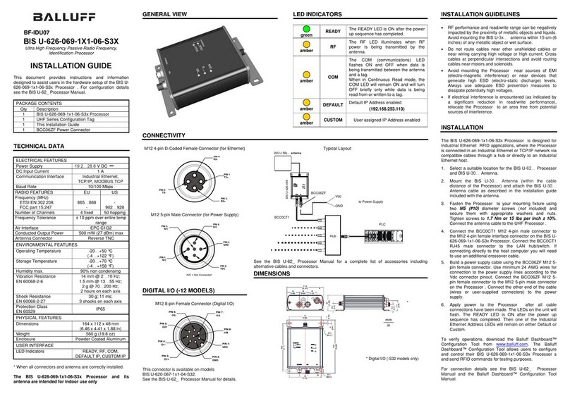
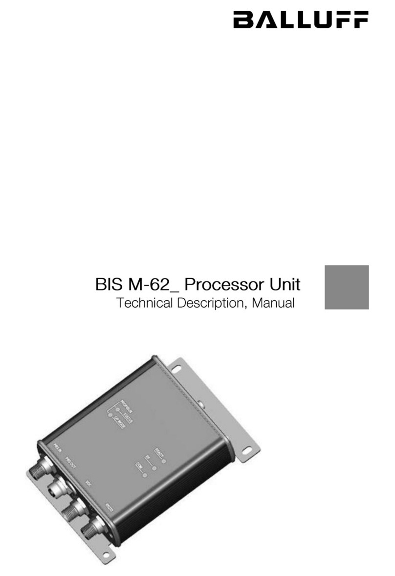
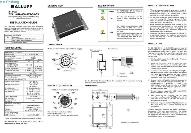
manuals.online logo
Brands
  1. Home
  2. •
  3. Brands
  4. •
  5. Balluff
  6. •
  7. Computer Hardware
  8. •
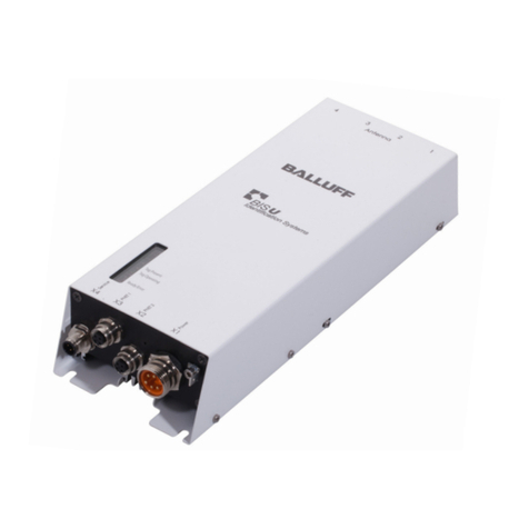
  9. Balluff BIS Series User manual

Balluff BIS Series User manual

Issue : October 12, 2005
No. T705802E
B
BALLUFF Identification System
Technical Manual for
BIS C-489-1_-KBT02Processor :
<>CC-Link interface
Safety instructions
()Read this section thoroughly before using the device
Before using the controller, read this manual carefully.
During installation and operation pay close attention to the safety aspect.
[]Planning the System
Design the system to work safety if the processor should be damaged or the power unit malfunction.
Do not exceed the specifications for supply voltage, conditions for use, etc. as indicated in this manual.
[]Handling the System
Observe the rated voltage that is indicated in the specifications.
Misuse may cause excessive heat leading to possible to fire.
Take care when connecting the system, as incorrect wiring may cause unexpected malfunction of
the machine.
Ensure the power is switched off during installation or maintenance operations.
Do not dismantle or modify the devices. This could cause malfunction or overheating.
[]Contents
1. Description
1.1 Description .......................................................................................1
1.2 Construction of the System.............................................................. 1
1.3 Construction of the components and applicable units..................... 2
2. Specifications
2.1 Specifications .................................................................................... 3
2.2 Efficiency............................................................................................ 3
2.3 Dimension ......................................................................................... 4
3. Function
3.1 List of Function.................................................................................. 5
3.1.1 Description of Function ............................................................ 6
3.2 Input-Output Signals for master unit ................................................ 7
3.2.1 List of Input-Output Signal ....................................................... 7
3.2.2 Details of Input-Output Signal ................................................... 8
3.3 Allocation of Remote Register .......................................................... 11
3.3.1 List of Remote Register ........................................................... 11
3.3.2 Details of Remote Register ........................................................ 12
3.4 Memory address of Code tag and Allocation of Block....................... 16
3.5 Data processing time ........................................................................ 20
4. Implementation and Installation
4.1 Installation ......................................................................................... 21
4.1.1 Mounting.................................................................................... 21
4.1.2 Positioning ..... .......................................................................... 21
4.2 Wiring ................................................................................................ 22
4.2.1 Cable for CC-Link .................................................................... 22
4.2.2 Wiring with each Unit ............................................................... 22
4.3 Each Part and Setting ....................................................................... 24
5. Instructions for Programming
5.1 Connecting the System and Processing Data..................................... 26
5.2 Construction of Data Processing unit ............................................ 26()
5.3 Memory of Code tag ........................................................................... 27
5.4 Interlock .............................................................................................. 28
5.5 Faulty Condition of Data Link ............................................................. 29
6. Communication with Code Tag
6.1 Instruction for Programming .................................................................. 30
6.2 List of Instructions and commands ....................................................... 32
6.3 Used System in this Chapter ................................................................ 33
6.4 Sequence Program for ACPU ............................................................... 34
6.5 Basic Format of Program ...................................................................... 35
6.5.1 Processing Program in Fault ........................................................ 37
6.6 Initial Setting .......................................................................................... 38
6.7 Reading Data Instruction ........................................................................ 43
6.7.1 Reading Instruction RD, CR ....................................................... 43()
6.7.2 Sequence Reading Instruction AR, SR .................................... 46()
6.8 Writing Data Instruction .......................................................................... 49
6.8.1 Writing Instruction WD, CW ........................................................ 49()
6.8.2 Sequence Writing Instruction AW, SW ..................................... 52()
6.8.3 Batch Writing Instruction FI ....................................................... 55()
6.9 Compare Instruction CM ..................................................................... 57()
6.10 Clear Instruction CL ......................................................................... 60()
6.11 Stop Command of Sequence Instruction ............................................... 62
6.12 Error Cancellation Instruction ................................................................. 63
6.13 Life Expectancy of Code Tag Information .............................................. 64
6.14.1 Reading Instruction of Life Expectancy of Code Tag Information....... 65
7. Trouble Shooting
7.1 List of Error Code ...................................................................................... 67
7.2 Trouble Shooting ....................................................................................... 68
7.2.1 Confirmation Procedure on LED indicator ............................................. 68
7.2.2 Procedure for Fault of Data Link ........................................................... 70
<>NOTE
1 The contents and the specification are subject to change without notice.()
2 Please inform us know if there is any mistake or notice in this manual.()
-1-
1. Description
1.1 Description
"Balluff Identification System / BIS series" is an identification system for factory automation that executes reading
and writing data by electromagnetic induction principle.
Processor BIS C-489 is connected to CC-Link as a remote device station, and it communicates with sequencer
CPU of master / local station .
There can be 2 read/write heads connected to the processor, and it executes read/write communication with code
tag per each channel separately.
It is possible to read or write data to code tag from sequencer CPU with programming an easy sequence program.
1.2 Construction of the System
CC-Link Master Local Station Processor Read/write Code
BIS C-489 Head tag
CH1
□Sequencer Master
CPU unit
CH2
□
CC-Link Cable for Head
()External power unit DC24V
Function of each Component
Component Function
Code tag A data medium that stores and retains information data .()
Read/write Head A Head that reads and writes information data in code tag without()
physical contact.
Supplies power for code tag.
Processor A Processor that executes reading or writing data to or from code tag when
it receives instructions from sequencer CPU.
It can be connected to 1 or 2 read/write head s .()
CC-Link A sequencer CPU unit that instructs for CC-link and a master unit station
Master/Local Station that controls CC-Link system.
[]Attention for Constructing of System
The occupied stations of Processor BIS C-489 are 4 stations.
Therefore, plural processors can be connected to a master unit if the number of processors
are not exceeding the connectable quantities.
Decide the number of processors to connect a master unit with regarding to following points.
1 Connectable station numbers for master unit. Maximum 16 stations .()()occupied 4 stations
2 Occupied station numbers of units input/output card etc. except processors,() ( )
and Input/Output occupied numbers.
3 Processing time or effect to tact time in programming ladder .() ( )
-2-
1.3 Construction of the Components and applicable units
The construction of components of CC-Link system that can be used by the processor BIS C-489 and applicable
units are indicated by the following.
The Processor cannot be connected to other units.
()CC-Link master / Local unit Sequencer CPU unit
Sequencer Type ACPU A1SHCPU, A1SJHCPU, A2SHCPU
CPU unit number A2UCPU, A2UCPU-S1, A3UCPU, A4UCPU
On and after software version Q. On and afer version K, available()only RRPA* function
A2USCPU, A2USCPU-S1
On and after software version E. On and afer version A, available()only RRPA* function
A2USHCPU-S1
On and after software version L. On and afer version G, available()only RRPA* function
QnACPU Q02CPU, Q2ACPU-S1, Q3ACPU, Q4ACPU, Q2ASCPU,
Q2ASCPU-S1, Q2ASHCPU, Q2ASHCPU-S1
()On and after function version B
QCPU A mode Q02CPU-A, Q02HCPU-A, Q06HCPU-A()
QCPU Q mode Q02CPU, Q02HCPU-A, Q06HCPU, Q12HCPU, Q25HCPU()
Master unit Type AJ61BT11,A1SJ61BT11,AJ61QBT11,A1SJ61QBT11
()Number On and after 9707B is indicated in DATE
QJ61BT11
()* Instruction RRPA Auto reflesh
CC-Link
Processor
External Power BIS C-489-1_-KBT02
()Unit DC24V
Read/write Head
BIS C-3**-**
Identification communication
Code tag
BIS C-1**-**
-3-
2. Specification
2.1 Specification
The followings are specifications of Processor BIS C-489.
()Operating temperature humidity 0...55 degree C, 10...90%RH without dew condensation
()Storage temperature humidity -20...75 degree C, 10...90%RH without dew condensation
Vibration rating Frequency Acceleration Amplitude Sweeping time
per JIS C 0911 10...57Hz - 0.075 10 timesmm
57...150Hz 1G - 1 octave/ 1min.*
()Shock rating per JIS C 0912 10G, 3 times to each axis XYZ
Noise durability Not to cause malfunction with noise simulator that has noise voltage 800V P-P,
noise width 1 micro S to external power unit DC24V noise frequency 25...60Hz.
Operating atmosphere Without corrosive gas, heavy dust
* 1 octave indicates increasing 2 times or decreasing 1/2 times of frequency.
ex. Each variation of frequency is indicated 1 octave such as,
from 10Hz to 20 Hz, from 20Hz to 40Hz, from 20Hz to 10Hz
2.2 Efficiency
Following are Efficiency of Processor BIS C-489.
Applicable read/write head BIS C-3**-**
Connecting procedure for head D-sub 9 pin connector
Connectable quantities of head 2 heads
Applicable code tag BIS C-1**-**
Using channel for r/w head Using only CH1 Using CH1, CH2
/()Number of RWr RWw each 16 words 8 words per each channel total 16
Communicating data
Communicating data 1...12 words 1...5 words
per 1 communicating
with master unit
Communicating data 1...512 words 1...512 words
per 1 communicating
withheadandcodetag
CC-Link version Ver. 1.10
Sort of CC-Link station Remote device station
()Occupied station 4 stations RX/RY each 128, RWr / RWw each 16
()Connecting terminal 7-screw terminal M3.5 x 7 screws
Suitable cable outer diameter mm 0.75...2.00()
2
()Suitable RAV1.25-3,RAV2-3.5 JIS C 2805
>( ・)Mounting screw for unit = M4 x 0.7mm x 16mm tightening torqe :78...118N cm
Supply voltage DC24V+-10%
Current consumption 0.8A
Cooling system Self cooling
Weight approx. 800g
() () ()Size 174W x100H x45D
-4-
2.3 Dimension
-5-
3. Functions
3.1 List of Function
The following function can be executed with the processor BIS C-489 .()
Instructions/ Instruction code Process ReferenceFunctions
Commands ASCII Hex.
Reading RD 4452H Reads data from code tag. 6.7.1Reading
CR 5243H Compares data to check.
Sequence AR 5241H Executes reading in sequence until code tag gets into 6.7.2
Reading SR 5253H communication area, and then executes reading.
After that, compares data to check.
Writing WD 4457H Writes data to code tag. 6.8.1Writing
CW 5743H Compares data to check.
Sequence AW 5741H Executes writing in sequence until code tag gets into 6.8.2
Writing SW 5753H communication area, and then executes writing .
After that, compares data to check.
Batch FI 4946H Writes specified data to specified area in code tag 6.8.3
writing simultaneously.
Check Comparing CM 4D43H Compares data of processor with data in code tag. 6.9
Clearance Clearing CL 4C43H Clears specified area in code tag with "0" 6.10
Command Sequence Cancels sequence instruction compulsively. 6.11
instruction
Cancellation
Error Executes error cancelling process. 6.12
cancellation Clearing error LED, resetting error detected signal,()Clearing executing result store area in remote resister
Life Reading Reads life "expectancy information" of code tag that written in
expectancy life expectancy LR 524CH code tag 6.13
of code tag
-6-
3.1.1 Description of Function
Description of the function of the processor BIS C-489 is explained in this chapter.()
Refer to "6. Communication procedure with Code tag" further details on function.
(1) Reading
Reads data in code tag.
<Reading Instruction (RD,CR)>
Reads data in code tag
<Sequence Reading Instruction (AR,SR)>
Reads data in code tag after waiting for the code tag to get into communication area of read/write head.
(2) Writing
Writes data to code tag.
<Writing Instruction (WD,CW)>
Writes data to code tag.
<Sequence Writing Instruction (AW,SW)>
Reads data in the code tag after waiting for code tag to get into communication area of read/write head.
<Batch Writing Instruction (FI)>
Writes specified 1-word data from specified address to specified area simultaneously.
(3) Check<Comparing (CM)>
Comparesdatainaprocessorwithreaddataincodetag.
(4) Clearance <Clearing (CL)>
Can be "0" data of specified area from specified address.
(5) Sequence Instruction Cancellation
Cancels sequence instruction (AR,SR,AW,SW) compulsively while instruction is executing.
(6) Error Cancellation
Cancels error condition after an error has occurred.
(7) Reading Life Expectancy of Code Tag <(LR)>
Reads "life expectancy of code tag information" that is written in code tag.
-7-
3.2 Input-Output Signals for Master Unit
Input-output signal RX, RY to the master unit is explained in this chapter.()
Device RX is the input signal from the processor to the master unit.[]
Device RY is the output signal from the master unit to the processor.[]
3.2.1 List of Input-Output Signal
Input-output signals of processor BIS C-489 are indicated in the following table.()
Signal direction : from processor to master unit Signal direction : from master unit to processor
Device No. (input) Device No. (output)
CH1 Signals SignalsCH2 CH1 CH2
RXn0 RXn8 RYn0 Selecting initial setting―――
RXn1 RXn9 Comparing result signal RYn1 Selecting processing unit
RXn2 RXnA Inzone RYn2 Selecting number of channel
―――RXn3 RXnB ID-BUSY RYn3 RYnB
RXn4 RXnC Finish identification instruction RYn4 RYnC Require executing
identification instruction
RXn5 RXnD Error detection RYn5 RYnD Unused
RXn6 RXnE Unused RYn6 RYnE Unused
RXn7 RXnF Require divided data RYn7 RYnF Finish divided data
RYn8...RYnA Unavailable
RX(n+1)0 RX(n+4)0
... ... Unused RY(n+1)0 RY(n+4)0
RX(n+3)F RX(n+6)F ... ... Unused
RY(n+3)F RY(n+6)F
RX(n+7)0...RX(n+7)7 Unavailable RY(n+7)0...RY(n+7)7 Unavailable
RX(n+7)8 Flag for requiring to RY(n+7)8 Flag for finishing to
process initial data process initial data
RX(n+7)9 Flag for finishing to RY(n+7)9 Flag for requiring to
set initial data set initial data
RX(n+7)A Unavailable
RX(n+7)B Remote READY RY(n+7)A...RY(n+7)F Unavailable
RX(n+7)C...RX(n+7)F Unavailable
n : Address that was allocated to the master station with setting station number.
<Attention>
The devices that indicated "Unavailable" should not be used by user because they are
used in the system.
If any "Unavailable" device is used by the user, normal operation would not be warranted.
-8-
3.2.2 Details of Input-Output Signal
Details of Input-Output signals of processor BIS C-489 are indicated in the following table.()
(1) Remote Input (RX)
Device No.
Signals ContentsCH1 CH2
Comparing result ON when comparing result is in agreement after reading, writingRXn1 RXn9 signal or comparing CR,SR,CW,SW,CM .()
It will be cleared with resetting of RYn4,RYnC, latch the other
setting with SET instruction when the comparing result is needed
to retain.
Inzone ON while inzone has been detected in executing sequenceRXn2 RXnA instruction (AR,SR,AW,SW).
ID-BUSY ON when instruction is executing, and OFF when the instructionRXn3 RXnB is finished excuting.
Finish identification ON after instruction is executed, and finished executing instructionRXn4 RXnC instruction normally.
It remains OFF when executing instruction is stopped with
sequence instruction cancellation while executing sequence
instruction (AR,SR,AW,SW). When error is occurred, it won't be
ON, and error detection signal (Xn5,XnD) will be ON.
Require executing
identification instruction
or special instruction
ID-BUSY
Finish identification
instruction
Error detection OFF when require executing identification instructionRXn5 RXnD RYn4,RYnC or special instruction RYn5,RYnD is OFF.() ()
Error cancel instruction
Require executing
identification instruction
or special instruction
Error detection
Executing error cancel
Error occur Executing error cancel
Unused UnusedRXn6 RXnE
Require divided data ON flag for requiring divided data to require next data whenRXn7 RXnF treating data exceeds certain quantity using 1 channel : 12(
words, 2 channel : 5 words . Executes reading or writing when)
require divided data flag is ON. ON finish divided data flag when
executing read or write data. After that, require divided data flag
will be OFF, then finish divided data flag.
Require divided
data
Executing read and write
Finish divided
data
-9-
Device No.
CH1 CH2 Signal Contents
RX(n+1)0 RX(n+4)0 Unused Unused
... ...
RX(n+3)F RX(n+6)F
RX(n+7)8 Flag for requiring ON, OFF timing of requiring to process initial data, finishing to
to process initial process, finishing to set, and requiring to set are indicated as
data follows.
Flag for requiring to process
initial data RX(n 7)8+
Flag for finishing to process
initial data RY(n 7)8+
Flag for finishing to set
RX(n+7)9 Flag for finishing initial data RX(n 7)9+
to set initial data Flag for requiring to set
initial data RY(n 7)9+
Execute initializing
Remote READY
RX(n 7)B+
Executed by sequence program
Executed by processor
RX(n+7)B Remote READY ON when processor finished setting of initial data and became
ready after power is on or resetting of hardware.
-10-
(2) Remote output (RY)
Device No.
CH1 CH2 Signals Contents
RYn0 Selecting initial Specify processing unit or number of channel to use with "user
setting setting" or "factory setting". By selecting "user setting", processing
unit, number of using channel could be selected by user.
OFF : User setting
ON : Factory setting
(Setting contents : word unit, both of CH1,CH2 are used)
RYn1 Selecting Specify processing unit of processing data. Setting is effective
processing when select initial setting (RYn0) is OFF (user setting).
unit It is only word unit setting.
OFF : word unit
ON : unused (to set ON, it will be word unit.)
RYn2 Selecting number Specify number of channel to use. Setting is effective when
of channel selecting initial setting (RYn0) is OFF (user setting).
OFF : both of CH1,CH2 are used
ON : only CH1 is used
RYn4 RYnC Require executing Executes instruction when require executing identification
ID instruction instruction is ON.
RYn5 RYnD Unused Unused
RYn6 RYnE Unused Unused
RYn7 RYnF Finish divided data Refer to RXn7, RXnF.
RY(n+1)0 Unused Unused
...
RY(n+6)F
RY(n+7)8 Flag for finishing to Refer to RX(n+7)8, RX(n+7)9.
process initial data
RY(n+7)9 Flag for requiring to
set initial data
-11-
3.3 Allocation of Remote Register
Allocation remote resistor of processor (BIS C-489) is explained in this chapter.
The remote resistor is set initial digit when power is supplied or sequencer CPU is reset.
3.3.1 List of Remote Resistor
Remote resistor of processor (BIS C-489) is indicated in the following table.
Using InitialDirection of Address
receiving Referencechannel Contents digitCH1 CH2
Writing area Specifying area for instruction 3.3.2 (1)RWwm RWwm+8 code ―――
master station Specifying area for first address 3.3.2 (2)RWwm+1 RWwm+9 ―――
3.3.2 (3)↓ RWwm+2 RWwm+A ―――Specifying area for processing number
Processor Specifying area for writing data 1Using both RWwm+3 RWwm+B
... 3.3.2 (4)... ... ―――
CH1&CH2 Specifying area for writing data 5RWwm+7 RWwm+F
3.3.2 (5)RWrn RWrn+8 ―――Storing area for instruction code result
Processor 3.3.2 (6)RWrn+1 RWrn+9 ―――Storing area for executing result
↓ RWrn+2 RWrn+A ――― ―――Unused
Reading area Storing area for reading data 1RWrn+3 RWrn+B
... ... 3.3.2 (7)... ―――
master station Storing area for reading data 5RWrn+7 RWrn+F
RWwm ――― ―――Unavailable
Writing area 3.3.2 (1)RWwm+1 ―――Specifying area for instruction code
master station Specifying area for first address 3.3.2 (2)RWwm+2 ―――
3.3.2 (3)↓ RWwm+3 ―――Specifying area for processing number
Processor Specifying area for writing data 1RWwm+4
... 3.3.2 (4)Using ... ―――
Specifying area for writing data 12RWwm+F
only CH1 RWrn ――― ―――Unavailable
Processor 3.3.2 (5)RWrn+1 ―――Storing area for instruction code result
3.3.2 (6)RWrn+2 ―――Storing area for executing result
↓RWrn+3 ――― ―――Unused
Reading area
Storing area for reading data 1RWrn+4
master station ... 3.3.2 (7)... ―――
Storing area for reading data 12RWrn+F
3.3.2 (8)RWwm ―――Specifying area for retry count
Writing area 3.3.2 (9)RWwm+1 ―――Specifying area for inzone detecting time
master station 3.3.2 (10)Initial Specifying area for interval ofRWwm+2 ―――
setting executing sequence instruction↓
RWwm+3 ―――Unavailable
Processor RWwm+4 ――― ―――... Unavailable
RWwm+F
m,n : Address that was allocated to master station with station number setting
<Attention>
The remote register that indicated "Unavailable" should not be used by the user because
they are used in the system.
If unavailable remote resistor is used by the user, normal operation would not be warranted.
-12-
3.3.2 Details of Remote Resistor
(1) Specifying area for instruction code
Specifies instruction to code tag.
[ex.] Specifying reading instruction (RD) (in using 2 channels)
Replaces upper byte and lower byte, and converts it to ASCII code then stores the code.
4452HInitial digit :
R D Instruction code
Replaces upper byte
and lower byte
DR
ASCII code 4 4 5 2
Specify ASCII code directly①
Specify 4452H(RD)
TOP Hn H4452 K1○
Store into specifying area for instruction code
Head I/O number of master unit
Change with ASC instruction②
Store 4452H
ASC RD D0
TOP Hn D0 K1○
Store into specifying area for instruction code
Head I/O number of master unit
Specifying area for the first address(2)
Specify the first address of code tag memory to read or write data.
:0...4095(0H...FFFH)Specifying range
:0Initial digit
[ex.] Specify address 120
First address
TOP Hn K120 K1○
Store into specifying area for first address
Head I/O number of master unit
<Attention>
Specify in the following range.
First address + Processing numbers =< 4096 (1000H)・
Specify in the range of memory capacity of the code tag.
-13-
(3) Specifying area for processing number
Specify processing number of data to be read or written.
:1...512(1H...200H)Specifying range
:1Initial digit
[ex.] Specify processing number to be 32 ()Processing number read/write
TOP Hn K32 K1○
Store into specifying area for processing number
Head I/O number of master unit
<Attention>
Specify in the following range.
First address + Processing numbers =< 4096 (1000H)・
Specify in the range of memory capacity of the code tag.
(4) Specifying area for writing data
Specify data to be written into code tag.
[ex.] Specify contents of D100...D104 to writing data (selected 2 channels).
First address of writing data
TOP Hn D100 K5○
Store into specifying area for writing data
Head I/O number of master unit
(5) Storing area for instruction code result
Stores instruction code that executed to processor BIS C-489 .()
(6) Storing area for executing result
Stores error code.
(7) Storing area for reading data
Stores reading data from code tag.
-14-
(8)Specifyingareaforretrycount(effectiveininitialsettingonly)
Specify retry time that processor BIS C-489 executes instruction when error occurs in data
communication.
: 0 ... 32767 (0 ... 32767 times) ... If the specified number is over 32767, the retrySpecifying range
time would be 32767 times.
:3Initial digit
[ex.]Specifyretrytimetobe5
Retry time
TOP Hn K5 K1○
Store into specifying area for retry time
Head I/O number of master unit
(9) Specifying area for inzone detecting time (valid in initial setting only)
Specifies standby time per 10ms when the code tag gets into communication area to inzone detection
starting communication in executing sequence instruction.()
: 0 ... 32767 (0 ... 327670 ms) ... if the specified number is over 32767, inzone detectionSpecifying range
time would be 327670ms
:0Initial digit
[ex.] Specify inzone detectingtimetobe2sec.
inzone detecting time
TOP Hn K200 K1○
Store specifying area for inzone detecting time
Head I/O number of master unit
Inzone detecting time is;
Standby time since code tag getting into communication area until starting communication.
By specifying this setting, it can communicate with avoiding unstable range.
-15-
(10) Specifying area for interval of executing sequence instruction (effective in initial setting only)
Specify executing instruction interval of sequence instruction per 100ms.
: 0 ... 32767 (0ms ... 3276700ms) ... if the specified number is over 32767, executingSpecifying range
interval would be 3276700ms
:0Initial digit
[ex.] Specify execution interval of sequence instruction to be 5 sec. (5000ms)
Set interval
TOP Hn ○ K50 K1
Store into specifying area for interval of executing sequence instruction
Head I/O number of master unit
Executing interval of sequence instruction
Read/write head
Executing sequence instruction !
(AR,SR,AW,SW)
Read/write head Code tag
Finish communicating with code tag !
This interval is executing interval.
Executes the next sequence instruction
after passing interval of executing sequence instruction.
Read/write head
Start executing next sequence instruction !
-16-
3.4 Memory Address of Code tag and Allocation of Block
Memory addressing of the code tag is per byte 8 bits , and there are "64 or 32 bytes" per page.()
Data communication identification communication between processor and code tag is executed per "page".()
Data process between sequencer and processor is executed per "word".
(1) Address construction of code tag "memory"
<>511 byte / code tag address
Processor : BIS C-489-13-KBT02
()Code tag address Hex.
Page byte address word address
START END START END
001F00F
1203F101F
2405F202F
3607F303F
4809F404F
5A0BF505F
6C0DF606F
7E0FF707F
8 100 11F 80 8F
9 120 13F 90 9F
A 140 15F A0 AF
B 160 17F B0 BF
C 180 19F C0 CF
D1A01BFD0DF
E1C01DFE0EF
F1E01FFF0FF
1 page = 32 bytes = 16 words※
<>Attention
Data process of the processor is executed per words.
The amount of communication data is up to 512 words.
-17-
<>1023 byte / code tag address
Processor : BIS C-489-14-KBT02
()Code tag address Hex.
page byte address word address
START END START END
001F00F
1203F101F
2405F202F
3607F303F
4809F404F
5A0BF505F
6C0DF606F
7E0FF707F
8 100 11F 80 8F
9 120 13F 90 9F
A 140 15F A0 AF
B 160 17F B0 BF
C 180 19F C0 CF
D1A01BFD0DF
E1C01DFE0EF
F1E01FFF0FF
10 200 21F 100 10F
11 220 23F 110 11F
12 240 25F 120 12F
13 260 27F 130 13F
14 280 29F 140 14F
15 2A0 2BF 150 15F
16 2C0 2DF 160 16F
17 2E0 2FF 170 17F
18 300 31F 180 18F
19 320 33F 190 19F
1A 340 35F 1A0 1AF
1B 360 37F 1B0 1BF
1C 380 39F 1C0 1CF
1D 3A0 3BF 1D0 1DF
1E 3C0 3DF 1E0 1EF
1F 3E0 3FF 1F0 1FF
1 page = 32 bytes = 16 words※
<>Attention
Data process of the processor is executed per words.
The amount of communication data is up to 512 bytes.

Other manuals for BIS Series

1

This manual suits for next models

1

Other Balluff Computer Hardware manuals

Balluff BIS C-6 0 Series User manual

Balluff

Balluff BIS C-6 0 Series User manual

Balluff U-626-069-1X1-06-S3X User manual

Balluff

Balluff U-626-069-1X1-06-S3X User manual

Balluff BIS M-620-068-A01-00-S Series User manual

Balluff

Balluff BIS M-620-068-A01-00-S Series User manual

Balluff ProfiNet BIS U-6028-048-104-06-ST28 User manual

Balluff

Balluff ProfiNet BIS U-6028-048-104-06-ST28 User manual

Balluff BIS M-62 Series User manual

Balluff

Balluff BIS M-62 Series User manual

Balluff BIS U-6026-034-104-06-ST35 User manual

Balluff

Balluff BIS U-6026-034-104-06-ST35 User manual

Balluff BIS L-405-037-00*-05-MU User manual

Balluff

Balluff BIS L-405-037-00*-05-MU User manual

Balluff BIS C-6002 User manual

Balluff

Balluff BIS C-6002 User manual

Balluff BIS U-620-068-1X1-00-SX User manual

Balluff

Balluff BIS U-620-068-1X1-00-SX User manual

Balluff BIS V-6106 Use and care manual

Balluff

Balluff BIS V-6106 Use and care manual

Balluff BIS C-6002 User manual

Balluff

Balluff BIS C-6002 User manual

Popular Computer Hardware manuals by other brands

Advantech USB-4750-AE user manual

Advantech

Advantech USB-4750-AE user manual

Linear Technology DC2012A Demo Manual

Linear Technology

Linear Technology DC2012A Demo Manual

Motorola 68HC12B32 user manual

Motorola

Motorola 68HC12B32 user manual

Nibe AMS 10-8 Service manual

Nibe

Nibe AMS 10-8 Service manual

NXP Semiconductors winbond MCX-N9 BRK Series quick start guide

NXP Semiconductors

NXP Semiconductors winbond MCX-N9 BRK Series quick start guide

Embedded Artists LPCXpresso DIAGRAMS

Embedded Artists

Embedded Artists LPCXpresso DIAGRAMS

Spectrum Digital XDS510USB installation guide

Spectrum Digital

Spectrum Digital XDS510USB installation guide

Linear Technology LT3740EDHC quick start guide

Linear Technology

Linear Technology LT3740EDHC quick start guide

Infineon CY8CPROTO-062S2-43439 user guide

Infineon

Infineon CY8CPROTO-062S2-43439 user guide

Nvidia Mellanox ConnectX-5 user manual

Nvidia

Nvidia Mellanox ConnectX-5 user manual

JETWAY NF835V Series user manual

JETWAY

JETWAY NF835V Series user manual

Primera Disc Publisher SE quick start guide

Primera

Primera Disc Publisher SE quick start guide

Miranda DENSITE series Guide to installation and operation

Miranda

Miranda DENSITE series Guide to installation and operation

Pasport PS-2142 instruction manual

Pasport

Pasport PS-2142 instruction manual

Cypress Semiconductor CY7C1012DV33 Specification sheet

Cypress Semiconductor

Cypress Semiconductor CY7C1012DV33 Specification sheet

Panasonic 2SA1309A Specification sheet

Panasonic

Panasonic 2SA1309A Specification sheet

Texas Instruments SimpleLink CC3200 Wi-Fi user guide

Texas Instruments

Texas Instruments SimpleLink CC3200 Wi-Fi user guide

Maxim Integrated MAX6340 Series manual

Maxim Integrated

Maxim Integrated MAX6340 Series manual

manuals.online logo
manuals.online logoBrands
  • About & Mission
  • Contact us
  • Privacy Policy
  • Terms and Conditions

Copyright 2025 Manuals.Online. All Rights Reserved.