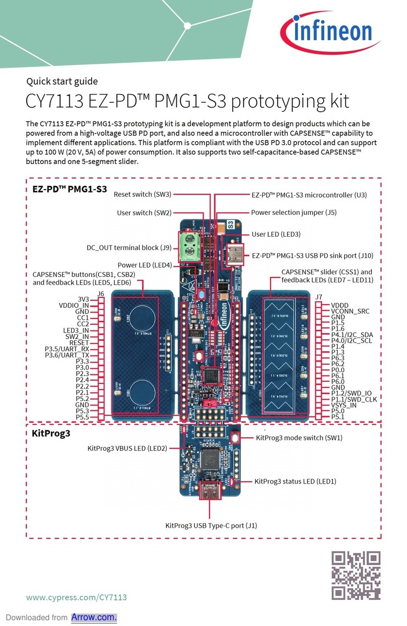
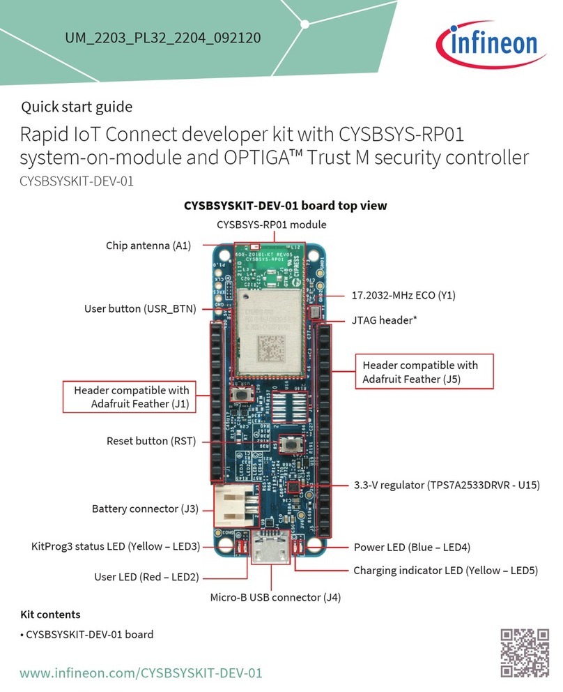
5. KitProg3 I/O headers (J6, J7): These headers bring out the USB-UART and USB-I2C interface pins of the
KitProg3. If the KitProg3 Section is broken away, it is also necessary to connect VTARG and GND as those are
used for voltage level translation. For more details on the KitProg3, see the KitProg3 user guide.
6. KitProg3 5-pin programming header (J4): This header brings out the SWD interface pins of the KitProg3.
This is used to program and debug the PSoC™6 MCU. If KitProg3 section is broken away, it can be used to
program any device over the 5-pin interface. Please note that VTARG is an input to KitProg3, and hence the
target must be powered externally in that case. The on-board regulators on the PSoC™6 MCU section
provide VTARG. For more details on the KitProg3, see the KitProg3 user guide.
7. PSoC™6 MCU I/O headers (J1, J2): These headers provide connectivity to PSoC™6 MCU GPIOs. Most of
these I/Os are also connected to on-board peripherals.
8. PSoC™6 MCU user LED (LED4): The user LED can operate at the entire operating voltage range of PSoC™6
MCU. The LED is active LOW, so the pins must be driven to ground to turn ON the LED.
9. PSoC™6 MCU: This kit is designed to highlight the features of the PSoC™6 MCU. For details on PSoC™6
MCU pin mapping, see Table 1.
10.Infineon PSoC™6 Wi-Fi BT Module (CY8CMOD-062S2-43439, U1): This kit is designed to highlight the
features of the PSoC™6 MCU on the CY8CMOD-062S2-43439. For details on see the module datasheet.
11.CYW43439 based Murata 1YN Module: The Type 1YN is a small and high-performance module which
supports Wi-Fi 802.11b/g/n + Bluetooth® 5.2 BR/EDR/LE up to 65Mbps PHY data rate on Wi-Fi and 3Mbps PHY
data rate on Bluetooth®. The WLAN section supports SDIO v2.0 interface and the Bluetooth® section
supports high-speed 4-wire UART interface and PCM for audio data. The CYW43439 implements highly
sophisticated enhanced collaborative coexistence hardware mechanisms and algorithms, which ensure
that WLAN and Bluetooth® collaboration is optimized for maximum performance. Type 1YN module is
packaged in an impressively small shielded form factor that facilitates integration into size- and power-
sensitive applications such as IoT applications, handheld wireless system, gateway.
12.Reset button (SW1): This button is used to reset the PSoC™6 MCU. This button connects the PSoC™6 MCU
reset (XRES) pin to ground.
13.On-board peripheral headers (J5, J11, J12 and J13): On-board peripherals are divided into sections. Each
section is independent and can be broken away from the PSoC™6 MCU section.
14.Digilent Pmod compatible SPI header (J16): This header can be used to connect Digilent Pmod 1 × 6 pin
SPI modules.
15.Digilent Pmod compatible I2S2 header (J15): This header can be used to connect Digilent Pmod 2 × 6 pin
I2S2 modules.
16.CAPSENSE™ buttons (BTN0 and BTN1): CAPSENSE™ touch-sensing buttons, capable of both self-
capacitance (CSD) and mutual-capacitance (CSX) operation, let you evaluate Infineon’ fourth-generation
CAPSENSE™ technology.
17.CAPSENSE™ slider: CAPSENSE™ touch-sensing slider capable of both self-capacitance (CSD) and mutual-
capacitance (CSX) operation. The slider and the buttons have a 1-mm acrylic overlay for smooth touch
sensing.
18.PSoC™6 MCU program and debug header (J14): This 10-pin header allows you to program and debug the
PSoC™6 MCU using an external programmer such as MiniProg4.Please note that this header is not loaded
by default.
19.PSoC™6 MCU user button (SW2): This button can be used to provide an input to the PSoC™ 6 MCU. Note
that by default the button connects the PSoC™ 6 MCU pin to ground when pressed, so you need to configure
the PSoC™ 6 MCU pin as a digital input with resistive pull-up for detecting the button press. This button also
provides a wake-up source from low-power modes of the device. In addition, this button can be used to
activate the PMIC control from PSoC™ 6 MCU.
20.System power selection jumper (J3): This jumper is used to select the PSoC™ 6 MCU’s supply voltage
(P6.VDD) between 1.8 V and 3.3 V.


