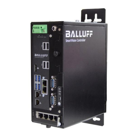
Balluff SmartVision BAE PD-VS-014-05 User manual

BAE PD-VS-014-05
SmartVision Controller
User’s manual

TABLE OF CONTENTS
1
BAE PD-VS-014-05
www.balluff.com
2USER INSTRUCTIONS ............................................................................................................3
2.1 Introduction............................................................................................................................................ 3
2.2 Typographical conventions.................................................................................................................. 3
2.2.1 Bulleted Lists..................................................................................................................................... 3
2.2.2 Actions............................................................................................................................................... 3
2.2.3 Numbers............................................................................................................................................ 3
2.2.4 Parameters........................................................................................................................................ 3
2.2.5 Directory paths .................................................................................................................................. 3
2.2.6 ASCII code ........................................................................................................................................ 3
2.2.7 Symbols............................................................................................................................................. 4
2.3 Abbreviations......................................................................................................................................... 5
2.4 Copyright................................................................................................................................................ 5
2.5 Legal requirements................................................................................................................................ 6
2.6 Updates and upgrades .......................................................................................................................... 6
2.7 Trademarks............................................................................................................................................. 6
3SAFETY....................................................................................................................................7
3.1 Intended use........................................................................................................................................... 7
3.2 General safety notes.............................................................................................................................. 7
3.2.1 General safety information ................................................................................................................ 7
3.2.2 Electrical safety notes ....................................................................................................................... 8
3.2.3 Safety notes for assembly................................................................................................................. 8
3.2.4 Safety notes for operation ................................................................................................................. 8
3.2.5 Conformity......................................................................................................................................... 8
3.2.6 Repairs.............................................................................................................................................. 8
3.2.7 Maintenance...................................................................................................................................... 9
3.3 Disposal................................................................................................................................................ 11
4PRODUCT DESCRIPTION.....................................................................................................12
4.1 Product variants................................................................................................................................... 12
4.2 Scope of delivery ................................................................................................................................. 13
4.2.1 Transport......................................................................................................................................... 14
4.2.2 Unpack and check supply unit......................................................................................................... 14
4.2.3 Identification data of the device....................................................................................................... 14
4.2.4 Ambient and environmental conditions ........................................................................................... 15
4.3 Wall mount............................................................................................................................................ 15
4.3.1 Mounting via mounting bracket ....................................................................................................... 16
4.3.2 Mounting via profile rail (only if the rail is pre-assembled).............................................................. 16
4.3.3 Installation of the device with wall-mounting kit .............................................................................. 18
4.4 Product specification .......................................................................................................................... 18
4.4.1 Mechanical data .............................................................................................................................. 18
4.4.2 Electrical data.................................................................................................................................. 19
4.4.3 Operating conditions ....................................................................................................................... 19
4.5 Connections and control elements.................................................................................................... 20
4.6 Display elements.................................................................................................................................. 21
4.6.1 Status LED ...................................................................................................................................... 21
4.6.2 Gigabit Ethernet Status LED........................................................................................................... 21
4.6.3 Cleaning .......................................................................................................................................... 22
5FIRST STEPS.........................................................................................................................23
5.1 Step 1: Establishing a network connection with the Balluff SmartVision Controller................... 23
5.2 Step 2: Switching on the Balluff SmartVision Controller ................................................................ 23
5.2.1 Connecting the DC power supply (19-28 V) via terminal clamp ..................................................... 24
5.3 Step 3: Opening the BVS Cockpit software ...................................................................................... 24
5.3.1 Setting up a camera ........................................................................................................................ 26

TABLE OF CONTENTS
2
BAE PD-VS-014-05
www.balluff.com
6STARTUP...............................................................................................................................27
6.1 Updating software................................................................................................................................ 27
6.2 Updating Balluff Camera firmware..................................................................................................... 28
6.3 Network topologies.............................................................................................................................. 29
6.4 System settings ................................................................................................................................... 30
6.4.1 Adapting the network settings ......................................................................................................... 31
6.4.2 Setting the system time................................................................................................................... 32
6.5 Selecting the communication interface for the process data ......................................................... 33
6.6 LAN Interface........................................................................................................................................ 35
6.6.1 LAN parameters in BVS Cockpit..................................................................................................... 35
6.7 Fieldbus interfaces .............................................................................................................................. 36
6.7.1 General fieldbus parameters in BVS Cockpit.................................................................................. 36
6.7.2 PROFINET fieldbus......................................................................................................................... 36
6.7.3 EtherNet/IP fieldbus ........................................................................................................................ 42
7APPENDIX..............................................................................................................................47
7.1 Troubleshooting Table ........................................................................................................................ 47
7.2 Type code ............................................................................................................................................. 47

2USER INSTRUCTIONS
3
BAE PD-VS-014-05
www.balluff.com
2.1 Introduction
These operating instructions describe the Balluff SmartVision Controller from the Balluff
Vision Solutions family BVS and the startup for an immediate operation.
The Balluff SmartVision Controller is a powerful inspection system, which runs BVS
Cockpit. BVS Cockpit is a browser-based software package that enables you to create
and configure inspection programs, without the need for any programmer or detailed
knowledge of image processing. As the "eye" for the inspection system, you can connect
both GigE Vision as well as USB3 Vision compliant industrial cameras like the Ball-
uff Camera BVS CA to the Balluff SmartVision Controller and operate them simultane-
ously.
The manuals for the BVS Cockpit and the Balluff Camera BVS CA are available in the
product download area on the Balluff product website via www.balluff.com
The Balluff SmartVision Controller is an inspection system for automated industrial envi-
ronments. Some outstanding properties are:
•Closed system based on an industrial PC
•Fieldbus connection (PROFINET, EtherNet/IP)
•Simultaneous operation of up to four industrial cameras and thus four inspections
programs
•Suitable for a cabinet installation
•Support of Industry 4.0
These operating instructions apply to the following variants of the Balluff SmartVision
Controller:
Ordering code
Product name
Description
BAE0103
BAE PD-VS-014-05
Balluff SmartVision Controller
2.2 Typographical conventions
The following conventions are used in this manual:
Enumerations are shown as a list with an en-dash.
•Entry1
•Entry 2
Action instructions are indicated by a preceding triangle. The result of an action is indi-
cated by an arrow.
1. Action instruction 1
a. Action result
2. Action instruction 2
•Decimal numbers are shown without additional indicators (e.g. 123).
•Fixed-point numbers are shown with a period (e.g. 0.123).
•Hexadecimal numbers are shown with the additional indicator hex (e.g. 00hex).
Parameters are shown in italics (e.g. CRC_16).
Path information for saving data is shown with fixed font width (e.g. Projekt:\Data
Types\Benutzerdefiniert).
Characters transmitted in ASCII code are set in apostrophes (e.g. 'L').
2.2.1 Bulleted Lists
2.2.2 Actions
2.2.3 Numbers
2.2.4 Parameters
2.2.5 Directory paths
2.2.6 ASCII code

2USER INSTRUCTIONS
4
BAE PD-VS-014-05
www.balluff.com
NOTE
A note indicates important information that helps you optimize us-
age of the products.
WARNING
A warning indicates how to avoid either potential damage to
hardware or loss of data.
ATTENTION
An attention indicates a potential for property damage, personal
injury, or death.
2.2.7 Symbols

2USER INSTRUCTIONS
5
BAE PD-VS-014-05
www.balluff.com
2.3 Abbreviations
ADC
Analog-to-digital converter
BVS
Balluff Vision Solutions
CA
Balluff Camera
CMOS
Complementary metal-oxide-semiconductor
DHCP
Dynamic Host Configuration Protocol
EEPROM
Electrical Erasable and Programmable ROM
EMC
Electromagnetic compatibility
FCC
Federal Communications Commission
FPGA
Field Programmable Gate Array
GenICam
Generic Interface for Cameras
GigE Vision
Image processing standard for Gigabit Ethernet interfaces
GND
Ground
HDMI
High Definition Multimedia Interface
I/O-Port
Digital input / output port
IO
Input / Output
IP
Internet Protocol
LAN
Local Area Network
LLA
Logical Link Address
MAC
Media Access Control
MTBF
Mean Time Between Failures
NC
Not connected
PC
Personal Computer
PLC
Programmable Logic Controller
RGB
Red Green Blue
RX
Receiver
SSD
Solid-State-Drive
TX
Transmitter
USB3 Vision
Image processing standard for USB 3.0 interfaces
2.4 Copyright
Copyright © Balluff GmbH, Neuhausen a.d.F., Germany, 2018. All rights reserved. In
particular: Right to duplication, modification, dissemination and translation into other
languages. Please note that all texts, graphics and images contained in these operating
instructions are protected by copyright and other protection laws. Commercial duplica-
tions, reproductions, modifications and disseminations of any type require the prior writ-
ten approval of Balluff GmbH. All information and notes in these operating instructions,
particularly the chapter Safety Instructions, must be observed.

2USER INSTRUCTIONS
6
BAE PD-VS-014-05
www.balluff.com
2.5 Legal requirements
The General Terms and Conditions of Balluff GmbH in their respective current version
and the conditions in these operating instructions exclusively apply to all deliveries of
products and to all other services of Balluff GmbH (henceforth referred to as “GTC”). The
provisioning of the software is exclusively subject to the respective current GTC, the
conditions in these operating instructions as well as the regulations of the “Balluff
Enduser Licensing Agreement”. You may use the software only in compliance with these
provisions. If they should not yet be available, Balluff GmbH will gladly provide the cur-
rent GTC upon request.
The driver of the Balluff Camera uses a variety of freely available tools which were pub-
lished under various open source licenses. Some licenses require that the source code
and modifications be published. These sources are published on the Product homepage.
The license texts for all software products used can be downloaded from the web inter-
face along with the manuals. They are available as ZIP files.
2.6 Updates and upgrades
Balluff GmbH is authorized –but not obligated –to make updates or upgrades of the
firmware available via the website of Balluff GmbH or in any other form. In such a case,
Balluff GmbH is authorized –but not obligated –to inform you about the updates or
upgrades. The use of such upgrades or updates assumes that you accepted the validity
of the current GTC as well as the additional conditions in the operating instructions.
2.7 Trademarks
The product, trade, company and technology designations used (e.g. Microsoft®, Win-
dows 7®, Internet Explorer®, Google Chrome®, Mozilla Firefox® and HALCON®) are
trademarks of the respective owners.

3SAFETY
7
BAE PD-VS-014-05
www.balluff.com
3.1 Intended use
The Balluff SmartVision Controller is an inspection system for creating inspection appli-
cations for different industrial areas. The insepction system provides a user interface for
connecting the camera via your web browser over network. Furthermore you create and
configure inspection programs with the user interface software "BVS Cockpit". You can
monitor and analyze the results of the inspection program.
The user interface is kept simple and understandable in order to enable a
fast learning process and to allow intuitive working. You will find more details in the "BVS
Cockpit Manual".
The intended use also includes that you have read these operating instructions in their
entirety and follow all the information –particularly the section “Safety”.
3.2 General safety notes
WARNING
Manufacturer's guarantee, warranty and liability are void for dam-
age caused by unauthorized tampering or unapproved use, instal-
lation or handling in violation of the specifications of this user's
guide. The operator must ensure that appropriate safety and acci-
dent prevention regulations are observed
When connecting the Balluff SmartVision Controller to an external
controller, observe proper selection and polarity of the connection
as well as the power supply (see “Connections and control ele-
ments”).
1. Please ensure secure standing when installing the Balluff SmartVision Controllers.
2. Please always let the inner components cool down before touching them to avoid
physical injury or property damage.
3. Ensure that the Balluff SmartVision Controller is supported correctly or fixed upright
before you install new accessories.
4. Ensure that no loose objects remain in the enclosure after maintenance work.
5. Set-up of the Balluff SmartVision Controller and maintenance work may only be
carried out by trained persons.
6. The Balluff SmartVision Controller is fitted with one replaceable battery. There is a
risk of explosion when replacing the battery improperly. Only replace the batteries
with the type recommended by the manufacturer or with an equivalent. Used batter-
ies have to be disposed of according to manufacturer’s directions.
3.2.1 General safety
information

3SAFETY
8
BAE PD-VS-014-05
www.balluff.com
1. Prior to connecting the device to the power supply, check if it complies to the values
stated on the equipment.
2. This device is designed for electricity from an earthed plug socket. The mains plug
with earthing device is an important safety feature. Do not switch off the earth to en-
sure protection against electric shock or property damage.
3. This system can be connected to an IT power supply. In any case, ensure that your
Balluff SmartVision Controller is also connected to the mass.
4. Please consider the positions of the power on/off button of the device and the safety
switch for the room to ensure fast switch off in case of an emergency.
5. Ensure that the device is always disconnected fully from the power supply before
opening the enclosure.
1. Increased operating ambient temperature - If the system is installed in an enclosed
module, then the operating temperature may be higher than the ambient tempera-
ture in the room. Therefore, you have to consider to install the Balluff SmartVision
Controller in an area which is compatible with the maximum ambient temperature
specified by the manufacturer.
2. Reduced airflow - The installation of the Balluff SmartVision Controller should be
completed in such a way that the air flow quantity which is required for equipment
operation is not impaired.
3. Mechanical load - The Balluff SmartVision Controller assembly should be carried out
in such a way that there are no hazardous operational conditions in the event of un-
even mechanical loads.
4. Circuit overload - The connection of the Balluff SmartVision Controller to the supply
current and the effect an overload of power circuits has on the overcurrent protec-
tion device and supply circuit cabling should be checked and considered carefully.
When dealing with this aspect, please carefully check specifically the load infor-
mation on the name plate of the device.
5. Reliable grounding - The Balluff SmartVision Controller has to be earthed reliably. It
is specifically important to consider the power connection cables and to a lesser de-
gree the direct connections to the sub-circuits (e.g. by using adapter strips).
1. Please shut down the operating system before disconnecting the Balluff SmartVision
Controller from the power supply in order to prevent any data loss.
2. Create free space in front of and behind the Balluff SmartVision Controller.
The Balluff SmartVision Controller conforms to therelevant safety regulations IEC, VDE,
and EN. If you have questions about the validity of the installation in the planned envi-
ronment, please contact your service representative.
Repair on the Balluff SmartVision Controller may only be carried out by authorised spe-
cialist personnel.
ATTENTION
Unauthorised opening and unprofessional repairs will cause fatal
shock hazard. Always disconnect device from power circuit (pull
power plug out) before touching components.
f_
•Always pull the mains plug before opening the Balluff SmartVision Controller.
•Only install system expansions which are intended for the Balluff SmartVision Con-
troller. Installation of additional expansions may damage the system or safety in-
structions and regulations for radio interference suppression may be violated. Infor-
mation as to which system expansions are suitable for installation can be obtained
from the technical customer service or from your outlet.
The warranty is void if you cause defects to the Balluff SmartVision Controller due to
installing or replacing system expansions.
3.2.2 Electrical safety
notes
3.2.3 Safety notes for
assembly
3.2.4 Safety notes for
operation
3.2.5 Conformity
3.2.6 Repairs

3SAFETY
9
BAE PD-VS-014-05
www.balluff.com
WARNING
Please observe ETUC information.
NOTE
In the interests of product improvement, Balluff GmbH reserves
the right to change the technical data of the product and the con-
tent of this manual at any time without notice.
Limitation of liability
All technical data and certifications are only valid for expansions.
No liability is accepted for functional losses when using third party equipment and com-
ponents.
Tools
You can carry out all assembly work on the equipment with a Phillips screwdriver type
PH1 and PH2.
Replace CMOS (CR2032) battery
Batteries are consumables and should be replaced every 3 years in order to ensure PC
functionality.
Please check the following prior to replacing
WARNING
Risk of explosion if battery is replaced by an incorrect type. Dis-
pose of used batteries according to the instructions.
ATTENTION
Risk of explosion and contaminant release! Therefore, do not
throw lithium batteries into fire, do not solder the cell body, do not
open, do not short circuit, do not switch poles, do not heat above
100°C, dispose off according to regulations and protect against di-
rect sunlight, humidity and condensation.
3.2.7 Maintenance

3SAFETY
10
BAE PD-VS-014-05
www.balluff.com
Preparation
BIOS settings, which deviate from optimised settings, will be lost. Date and time will have
to be set again after replacement.
1. Note down the current BIOS set-up settings.
2. Disconnect the equipment from the grid and pull off all connection cables from it.
ATTENTION
The battery replacement must not occur if the equipment is still
running. Disconnect the equipment from the mains voltage!
Work steps
1. Open the revision cover.
a. Loosen two screws (1)
using a
crosstip screwdriver.
2. Remove the battery from the
holder.
a. Press the latching
catch (2) downwards
using your finger.
3. Insert the new battery.
a. In reverse order.
4. Close the cover.
5. Adjust the BIOS set-up settings.
Replace the dust filter
The dust filter can be replaced as needed.
ATTENTION
The dust filter replacement must not occur if the equipment is still
running. Disconnect the equipment from the mains voltage!
Work steps
1. Loosen the side cover (knurled screw).
2. Open the side cover.
3. Remove the dust filter.
4. Insert a new dust filter.
5. Close the side cover.

3SAFETY
11
BAE PD-VS-014-05
www.balluff.com
3.3 Disposal
This product is covered by WEEE Directive 2012/19/EU on waste electrical
and electronic equipment.
Dispose of the product properly and not as a part of the regular waste
stream. The regulation of the respective country are to be observed. Infor-
mation is provided by the national authorities.

4PRODUCT DESCRIPTION
12
BAE PD-VS-014-05
www.balluff.com
The Balluff SmartVision Controller is an inspection system, which application areas are
optical identifications, inspections for quality assurance, and the measurement of ob-
jects. With the LAN interfaces you can integrate the Balluff SmartVision Controller into an
existing network. Additionally, the Balluff SmartVision Controller offers two fieldbus con-
nectors. Via USB 3.0 and Gigabit Ethernet ports you can connect USB3 Vision and GigE
Vision compliant industrial cameras.
The Balluff SmartVision Controller works with the he Balluff BVS Cockpit interface devel-
oped specifically for camera systems. Here, the Balluff SmartVision Controller makes it
possible to run Balluff BVS Cockpit and independent inspections simultaneously.
Figure 1 Balluff SmartVision Controller
4.1 Product variants
The Balluff SmartVision Controller is developed according to the latest industrial stand-
ards:
CPU
Intel® Core i7-6700TE
Chipset
Intel® Q170 Chipset
iAMT
11.0
Memory
16 GB DDR4
Graphics
Intel® HD graphics 530
Drives
1x 256GB 2,5“ SATA SSD (changeable via tray)
LAN
2x Gigabit Ethernet (Intel® i211AT / i219LM / i350)
For industrial cameras
4x Gigabit Ethernet (Intel® i211AT / i219LM / i350)
Fieldbus
Profinet

4PRODUCT DESCRIPTION
13
BAE PD-VS-014-05
www.balluff.com
Cooling
Active
Front I/O
4x USB 3.0 for industrial cameras
4x Gigabit Ethernet for industrial cameras
4x USB 2.0
1x Support port (DisplayPort)
2x Support port (RS232)
2x LAN RJ45
2x Fieldbus RJ45
1x SSD Tray
Switch / LED
DC in
Power supply
19 - 28V DC in (Phoenix plug)
Dust protection
1x dust filter
Mounting options
Wall and DIN Rail mounting
MTBF
@25°C 54515h, @45°C 48804h
4.2 Scope of delivery
Included in the scope of delivery
•Balluff SmartVision Controller
•HALCON dongle
•Wall mount and DIN Rail holder
•Quick Start Guide
•General Safety Notes
NOTE
Visit www.balluff.com for more information on available software
and accessories.

4PRODUCT DESCRIPTION
14
BAE PD-VS-014-05
www.balluff.com
Despite the solid design of the Balluff SmartVision Controller, the fitted components are
susceptible to strong vibrations and impacts. Therefore, protect the PC during transport
against great mechanical stresses.
Only use the original packaging when shipping and transporting the Balluff SmartVision
Controller.
WARNING
Risk of equipment damage!
For transports in cold weather, when the PC is subjected to ex-
treme temperature differences, you have to ensure that no humidi-
ty can deposit on the Balluff SmartVision Controller (condensa-
tion).
In case of condensation, the Balluff SmartVision Controller may
only be switched on after approx. 12 hours.
Please consider the following points during unpacking.
•We recommend that you keep the original packaging. Please keep it for possible
future transport.
•Please keep the accompanying documentation. You need this for initial commission-
ing and they are part of the Balluff SmartVision Controller.
•Please check the packaging and packaging content for any visible transport dam-
age.
•Check that the delivery and any extra accessories are complete.
If you notice any transport damage or any irregularities, then please inform us.
The Balluff SmartVision Controller can be identified clearly in case of necessary repairs
thanks to the identification data.
Figure 2 Name plate
Figure 3 Serial number
Furthermore, the MAC addresses of the LAN connectors are noted:
Figure 4 MAC-Adressen
4.2.1 Transport
4.2.2 Unpack and check
supply unit
4.2.3 Identification data
of the device

4PRODUCT DESCRIPTION
15
BAE PD-VS-014-05
www.balluff.com
Please observe the following points for operational planning:
•Consider the climate and mechanical environmental conditions in the system fea-
tures.
•The Balluff SmartVision Controller was designed for use in a normal industrial envi-
ronment. Without additional measures (supply of clean air), you cannot use the Pyr-
amid IPC in places with difficult operational conditions due to corrosive vapours or
gases.
•The free space in the area around the air vents has to be at least 10 cm to ensure
sufficient ventilation for the IPC.
•The air vents of the enclosure must not be covered.
•It is imperative to consider the permissible installation positions when assembling
the Balluff SmartVision Controller.
Permissible installation positions
The following installation positions have to be observed:
Vertical, fixing points on the front
Horizontal, fixing points on the front
4.3 Wall mount
The Balluff SmartVision Controller features suitable mounting possibilities for installation
in a control cabinet.
To mount the Balluff SmartVision Controller at a wall, there are two possibilities:
1. Mounting via mounting bracket
2. Mounting via profile rail (only if the rail is pre-assembled)
4.2.4 Ambient and en-
vironmental condi-
tions
WARNING
Be sure, that there is sufficient air circulation available at the fan
and the filter inlet for cooling of the device.

4PRODUCT DESCRIPTION
16
BAE PD-VS-014-05
www.balluff.com
Use the supplied mounting bracket (see gray area below).
1. First, fasten the bracket on the back of the Balluff SmartVision Controller using 4
supplied screws.
2. Use the additional 2 screws, to mount the Balluff SmartVision Controller at a wall.
Figure 5 Front view with assembled mounting bracket
Figure 6 Rear view with screwing points
Use the supplied profile rail (see image below) and assemble it on the back of the Balluff
SmartVision Controller. The profile rail can be assembled vertically or horizontally. After-
wards, you can mount the Balluff SmartVision Controller in a control cabinet.
Figure 7 Profile rail top view
4.3.1 Mounting via
mounting bracket
4.3.2 Mounting via pro-
file rail (only if the
rail is pre-
assembled)

4PRODUCT DESCRIPTION
17
BAE PD-VS-014-05
www.balluff.com
Figure 8 Profile rail side view
Figure 9 Rear view with vertical screwing points
Figure 10 Rear view with horizontal screwing points

4PRODUCT DESCRIPTION
18
BAE PD-VS-014-05
www.balluff.com
With the wall-mounting kit you have the possibility to realize a space saving assembly.
Material
Bore diameter
Mounting
Concrete
8 mm
Dowel 8M, 50 mm
Screws 5 mm x 60 mm
Gypsum
(min. 13 mm thick)
14 mm
Toggle bolts
Diameter 4 mm
Length min. 50 mm
Metal
(min. 3 mm thick)
5 mm thread
Metal screws
Diameter 5 mm
Washer ø 10 mm
Length min. 10 mm
WARNING
Ensure that the wall can hold at least 4 times the total weight of
the equipment (including mounting brackets and additional expan-
sion modules). The total weight is approx. 2.7kg.
4.4 Product specification
Housing material
Sheet steel galvanised; powder coated black
Degree of protection
IP20
Weight
approx. 2.7 kg
Dimensions (W × D × H)
216 x 191 x 88 mm
f_
Figure 11 Dimensional drawing back
4.3.3 Installation of the
device with wall-
mounting kit
4.4.1 Mechanical data

4PRODUCT DESCRIPTION
19
BAE PD-VS-014-05
www.balluff.com
Figure 12 Dimensional drawing top
Supply voltage
19V - 28V DC
Max. current consumption without external load
85 W
WARNING
The Balluff SmartVision Controller and accessories must be sup-
plied by Limited Power Source (LPS) according to UL/IEC 60950-1
or Class 2 source according to UL 1310.
f_
Ambient temperature
10 .. 50 °C / 10 .. 80 % relative humidity
Storage temperature
-10 .. 70 °C / 10 .. 95 % relative humidity
Operation
Internally
4.4.2 Electrical data
4.4.3 Operating conditi-
ons
Other manuals for SmartVision BAE PD-VS-014-05
2
This manual suits for next models
1
Table of contents
Other Balluff Controllers manuals
Popular Controllers manuals by other brands

GESTRA
GESTRA LRR 1-52 installation instructions

Drucegrove
Drucegrove IND055 user manual

Bodine
Bodine GTD20A installation instructions

14POINT7
14POINT7 Edge AFR manual

CD Automation
CD Automation Revo Revex RX3 Series user manual

EnvironmentalLights.com
EnvironmentalLights.com touch-panel-rgb quick start guide