CAREL保留不预先告知即修改产品的权力。
CAREL reserves the right to modify the features of its products without prior notice.
+05C002870 - rel. 1.3 - 17.11.2005
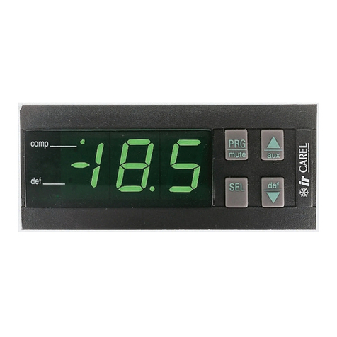
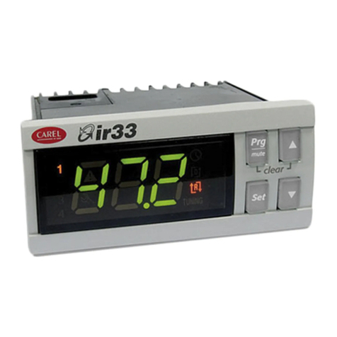
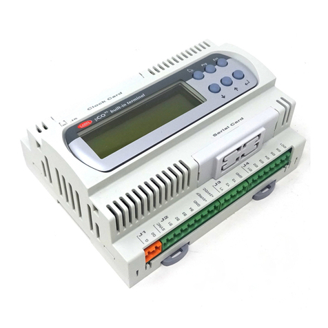
用户界面
三位数码显示(有正负号和小数点),黄色运行信号和红色报警信号。
图标 颜色 含义 参考回路
LED灯亮 LED闪烁
1,2 黄色 压缩机1和/或2开机 启动请求 1
3,4 黄色 压缩机3和/或4开机 启动请求 2
黄色 至少有一个压缩机开机 1和/或2
黄色 水泵/出风风机开启 1和/或2
黄色 冷凝风机开机 1和/或2
黄色 除霜动作 启动请求 1和/或2
黄色 电加热工作 1和/或2
红色 报警动作 1和/或2
黄色 热泵模式 (P6= 0) 1和2
黄色 制冷模式 (P6= 0) 1和2
按键功能
按键 机组状态 按键按压模式
上载默认值 机组上电时按压
可进入编程区域,直到退出(保存更改至E2PROM)按压一次
在报警事件中,蜂鸣器消音(如存在),取消报警继电器 按压一次
访问直接参数 按压5秒
选择编程项,显示直接参数的值/确认参数的更改 按压一次
+
输入口令后的编程参数 按压5秒
在编程区域选择高级项目 按压一次或一直按
增加数值 按压一次或一直按
从待机状态转成制冷状态(P6=0)和相反 按压5秒
在编程区域选择低级项目 按压一次或一直按
减少数值 按压一次或一直按
从待机状态转成热泵状态(P6=0)和相反 按压5秒
+
手动报警复位 按压5秒
立即复位小时计时器 按压5秒
+ 两个回路强制手动除霜 按压5秒
技术参数
“A组”在下面的技术参数中定义成如下输出组:阀,水泵,压缩机,电加热器。
电源 24 Vac, –15+10 %; 50/60 Hz
最大电流输出: 3 W
μC²回路上的所配保险丝为: 315 mAT
12针接头 每一个继电器输出的最大电流为2A;有一个输出可扩大为3A
继电器 在250Vac情况下:
EN60730:电阻:3A;电感: 2 A cos φ= 0.4 60000循环
UL:电阻:3A,1FLA , 6 LRA cos φ= 0.4 30000循环
对于更多信息参看图5特性图
开关循环间(每一个继电器)的最小间隔:12S
继电器的微型开关类型:1C
继电器A组的间的绝缘:基本型
继电器A组与低压绝缘部间的绝缘:增强型
继电器A组与信号继电器间的绝缘:初级
信号继电器与低压绝缘部间的绝缘:增强型
继电器与前面板间的绝缘:增强型
开关量输入 ID1...ID5, IDB4 电气标准:无源干触点
对地闭合电流:5mA
最大闭合电阻:50W
模拟量输入 B1,B2,B3,B4:卡乐NTC型温度传感器(25℃时10kW)
反应时间取决于所使用的元件,典型数值是90S
B4:NTC型传感器(25℃时10kW)或卡乐0-5V电源温度传感器或无源触点型公制压
力传感器
风机输出 卡乐MCHRTF****,CONVONOFF*和CONV0/10A*R的控制信号
脉冲信号调节(设置振幅)或值日循环调节,参看用户手册的配置参数部分
无负载电压:5V±10%
短路电流:30mA
最小输出负载:1KW
前面板防护等级 IP55
存储条件 -10-70 °C - 湿度 80% rH;无凝露
运行条件 -10T55 °C - 湿度 <90% rH;无凝露
污染等级 正常
阻燃特性 D (UL94 V0)
绝缘材料的PTI ≥ 250 V
软件结构和等级 A
绝缘部件抗电击周期 长
注意:所有继电器的公共端(C1/C2,C3/C4)必须连接在一起,参看图2。
功能方面技术参数
模拟量输入精度 温度传感器:范围 -40-80 °C, 0.1 °C
温度测量误差 范围 -20-20 °C, ±0.5 °C (不包括传感器)
范围 -40-80 °C, ±1.5 °C (不包括传感器)
压力测量误差 输入范围为0.5—4.5Vdc的电压误差为±2%(不包括传感器)。根据参数的设
置/9,/10,/11,/12,转换的数值可能有变化(参看用户手册)
用户界面/ User interface
Fig. 4
继电器触点电气特性
Electrical specications of the relay contacts
Fig. 5
User interface
Green 3 digit display (plus sign and decimal point), amber operating signals and red alarm signal.
Symbol Colour Meaning Reference refrigerant
circuit
with LED on with LED ashing
1,2 Amber Compressor 1 and/or 2 On Start request 1
3,4 Amber Compressor 3 and/or 4 On Start request 2
Amber At least one compressor on 1 and/or 2
Amber Pump/air outlet fan on 1 and/or 2
Amber Condenser fan on 1 and/or 2
Amber Defrost active Defrost request 1 and/or 2
Amber Heater on 1 and/or 2
Red Alarm active 1 and/or 2
Amber Heat pump mode (P6=0) 1 and 2
Amber Chiller mode (P6=0) 1 and 2
Functions of the buttons
Button Unit status Button press mode
Loading default values Press at power on
Go up a sub-group inside the programming area, until exiting (saving
changes to E2PROM)
Press once
In the event of alarms, mute the buzzer (if present) and deactivate the
alarm relay
Press once
Access the direct parameters Press for 5 s
Select item inside the programming area and display value of direct
parameters / conrm the changes to the parameter
Press once
+
Program parameters after entering password Press for 5 s
Select top item inside the programming area Press once or press and hold
Increase value Press once or press and hold
Switch from standby to chiller mode (P6=0) and vice-versa Press for 5 s
Select bottom item inside the programming area Press once or press and hold
Decrease value Press once or press and hold
Switch from standby to heat pump mode (P6=0) and vice-versa Press for 5 s
+
Manual alarm reset Press for 5 s
Immediately reset the hour counter (inside the programming area) Press for 5 s
+ Force manual defrost on both circuits Press for 5 s
Technical specications
“Group A” is dened in the following specications as the grouping of the following outputs: valve, pump,
compressor, heater.
Power supply 24 Vac, range –15% ~ +10%; 50/60 Hz
Maximum current output: 3 W
Fuse to be tted in series with the power supply of the μC2: 315 mAT
12-pin connector Max current 2 A for each relay output, extendable to 3 A for one output
Relays Max current at 250 Vac:
EN60730: Resistive: 3 A, Inductive: 2 A cosφ= 0.4 60000 cycles
UL: Resistive 3 A, 1 FLA , 6 LRA cos φ= 0.4 30000 cycles
For further information, refer to the characteristic shown in Fig. 5
Minimum interval between switching cycles (each relay): 12 s (the manufacturer of
the unit that the device is built into must ensure the correct conguration to respond
to this specication)
Type of micro-switching of the relay: 1 C
Insulation between relays in group A: functional
Insulation between relays in group A and the very low voltage parts: reinforced
Insulation between relays in group A and the signal relay: primary
Insulation between the signal relay and the very low voltage parts: reinforced
Insulation between relays and the front panel: reinforced
Digital inputs ID1 to ID5, IDB4 Electrical standard: voltage-free contact
Closing current to ground: 5 mA
Maximum closing resistance: 50 W
Analogue inputs B1, B2, B3, B4: CAREL NTC temperature probes (10 kW at 25 °C)
The response time depends on the component used, typical value 90 s
B4: NTC temp. probes (10 kW at 25 °C) or CAREL 0 to 5 V or free contact ratiome-
tric pressure probes
Fan output Control signal for CAREL MCHRTF****, CONVONOFF* and CONV0/10A* modules
Modulation of impulse position (set amplitude) or modulation of the duty-cycle. Refer
to the user manual for the conguration of the parameters
Loadless voltage: 5V ± 10%
Short-circuit current: 30 mA
Minimum output load: 1 kW
Front panel index of protection IP55
Storage conditions -10T70°C -- humidity 80% r.H., non-condensing
Operating conditions -10T50°C - humidity <90% r.H., non-condensing
Degree of pollution normal
Cat. of resist. to heat and re D (UL94 V0)
PTI of the insulating materials ≥ 250 V
Class and structure of the software A
Period of electrical stress across
the insulating parts
long
Note: All the relays must have the commons (C1/2, C3/4) connected together, as shown in Fig. 1.
Functional specications
Resolution of analogue inputs Temperature probes: range -40T80°C, 0.1 °C
Temperature measurement
error
Range -20T20 °C, ±0.5 °C (excluding probe)
Range -40T80 °C, ±1.5 °C (excluding probe)
Pressure measurement error The voltage % error in the input range of 0.5 to 4.5 Vdc is ± 2% (excluding probe). The er-
ror in the converted value may vary according to the setting of the parameters /9, /10, /11,
/12 (see user manual)
CAREL S.p.A.
Via dell’Industria, 11 - 35020 Brugine - Padova (Italy)
Tel. (+39) 0499716611 – Fax (+39) 0499716600
