BANLAW 800 Series Operational manual

PRODUCT DATA SHEET
Dry-Break Diesel Refuelling Nozzles
Banlaw ReFuelling™
Doc ID: PRH-REF-70 Version: 7.0 Page 1of 32
Please ensure you have the latest version of this document.
Thank you for purchasing this high quality Banlaw product. Please read through and
understand the information in this Product Data Sheet (PDS) BEFORE installation or operation
of the product to avoid accidental personal injury or property damage.
1PRODUCT DESCRIPTION
Banlaw Dry-Break Diesel Refuelling Nozzles are fluid (e.g. diesel fuel) dispensing couplings which
incorporate both calibrated (automatic) pressure shut-off, and “dry break”functions.
Banlaw introduced their first dry-break diesel refuelling nozzles into the market in the 1980’s in
response to a requirement for a more ergonomic and robust “industry standard” nozzle rated for higher
diesel flowrates.
800 Series
1000 Series
Figure 1 - Examples of Banlaw Nozzles
Figure 1 shows examples of current Banlaw 800 and 1000 series Nozzles. The “800” refers to the
maximum rated diesel flowrate of 800LPM (211GPM) of the 800 series, and likewise the “1000” refers
to the maximum rated diesel flowrate of 1000LPM (264GPM) of the 1000 series.
Banlaw Nozzles are available in a variety of models (variants) within each series, including the Banlaw
FuelTrack™Nozzles incorporating the Banlaw proprietary automatic (vehicle) identification –i.e. “auto
ID” – feature. Banlaw Nozzles also incorporate other features including the patented#means of
adjusting the automatic shut-off setting (#US 6,622,760).
The 800 series “Mining” Nozzles are compatible with the industry standard refuelling “receivers”,
commonly used as the means of refuelling plant equipment and smaller bulk diesel storage tanks in the
mining and construction industries. Other 800 series models –e.g. “Rail” – and Banlaw 1000 series
Nozzles are only compatible with the matching Banlaw receiver.
This document specifically covers the principal specifications, installation, commissioning, operation,
maintenance and servicing requirements and guidelines of Banlaw 2” (DN50) Diesel Refuelling and Fluid
Transfer Nozzles. End-users requiring additional information should refer to the Banlaw website,
contact Banlaw or your nearest authorised Banlaw distributor. Similarly, persons wanting information
other Banlaw refuelling products and Nozzle accessories should also refer to the website or same
contacts.

BANLAW PRODUCT DATA SHEET DRY-BREAK DIESEL REFUELLING NOZZLES
Doc ID: PRH-REF-70 Version: 7.0 Page 2of 32
Please ensure you have the latest version of this document.
CAUTION
The content of this document is not meant to override or substitute any
applicable Statutory, Regulatory, Customer/Site, etc. Health Safety &
Environment (HS&E) requirements.
All works should only be performed by trained, qualified and competent
personnel who are aware of the hazards associated with the constituent
components of this installation in addition to the “system” as a whole. Failure to
comply with these practices may result in death, serious bodily injury, loss of
equipment and environmental damage.
A risk assessment (job hazard analysis - JHA) should be conducted PRIOR to the
start of any works or actions within this document. Whilst every effort has been
made to ensure the execution of this document represents no HS&E hazard,
Banlaw takes neither responsibility nor liability for the consequences and
damages that may occur in the execution of works within this document.
Persons conducting or otherwise involved with the execution of the works within
this document and project have an obligation to ensure that all HS&E
requirements are known and understood, and subsequently followed at all times.
Contents
1PRODUCT DESCRIPTION..............................................................................................................................................................................1
1.1 Glossary of Terms ....................................................................................................................................................................................3
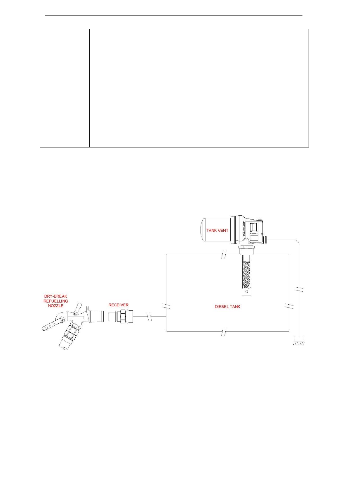
1.2 System Overview .....................................................................................................................................................................................4
1.3 Key Features.............................................................................................................................................................................................5
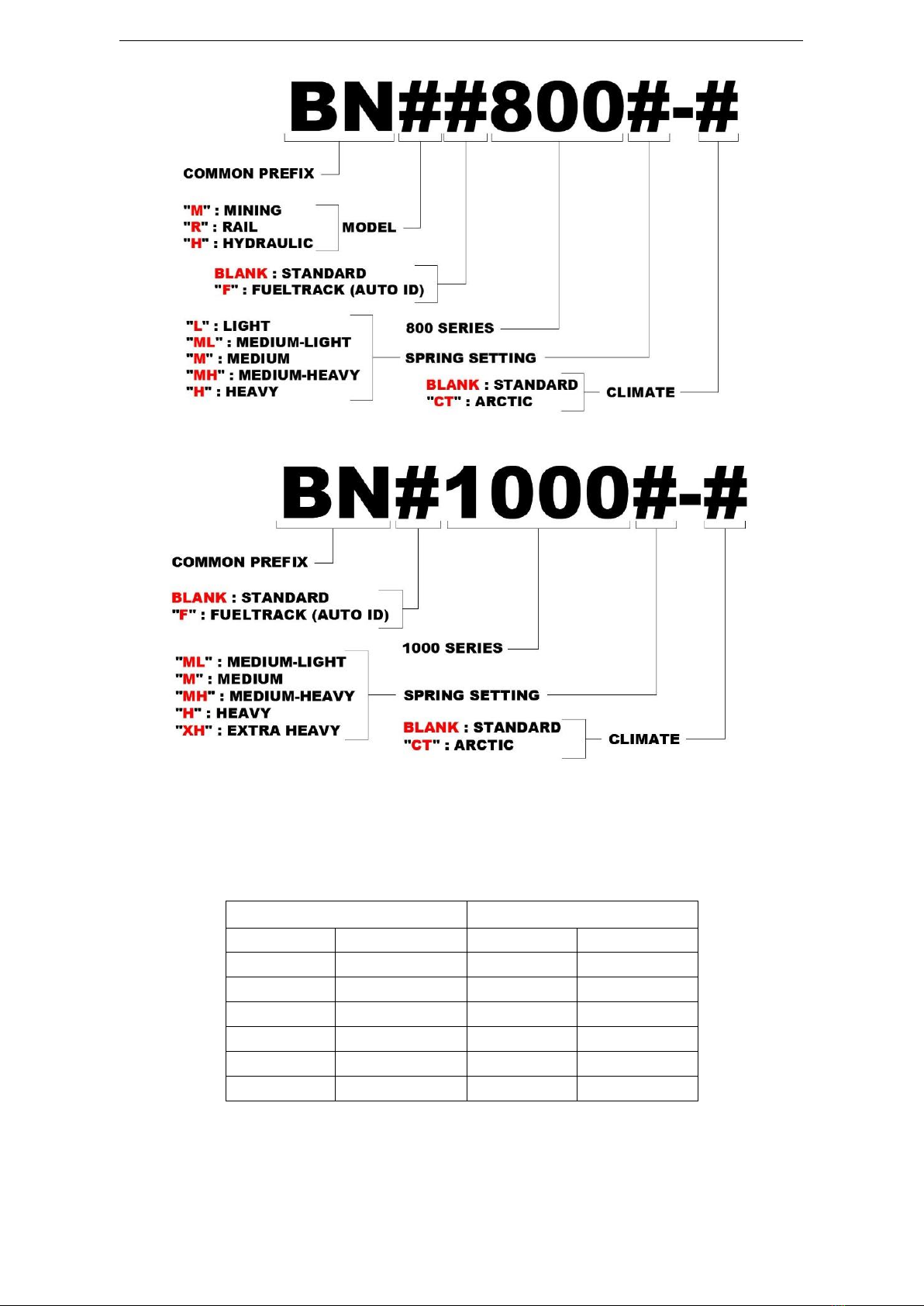
1.4 Part Numbering........................................................................................................................................................................................ 6
1.5 Available Nozzle Models.......................................................................................................................................................................... 7
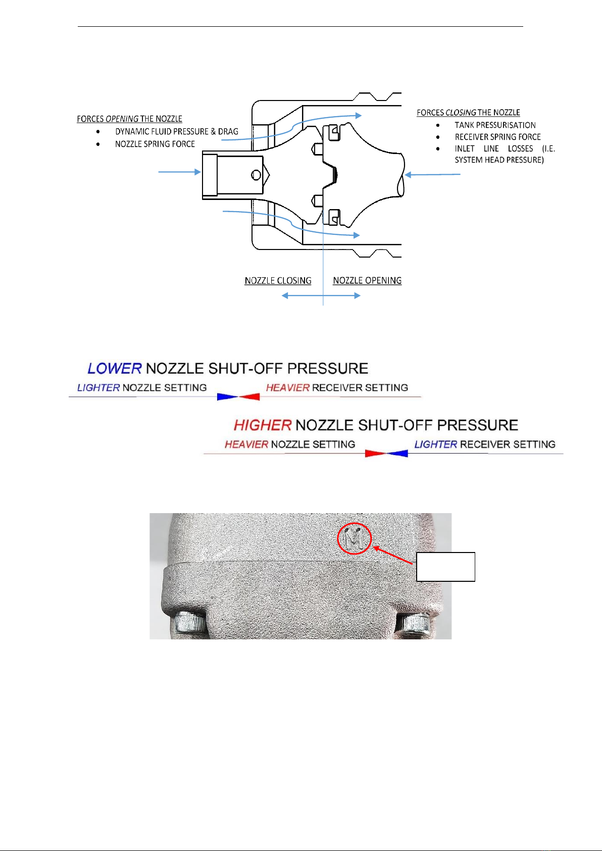
1.6 Nozzle Spring Settings.............................................................................................................................................................................. 8
1.7 FuelTrack Nozzle Variants...................................................................................................................................................................... 10
1.8 Nozzle and Receiver Compatibility ........................................................................................................................................................ 11
2IMPORTANT RESTRICTIONS ON THE USE OF THIS PRODUCT...................................................................................................................12
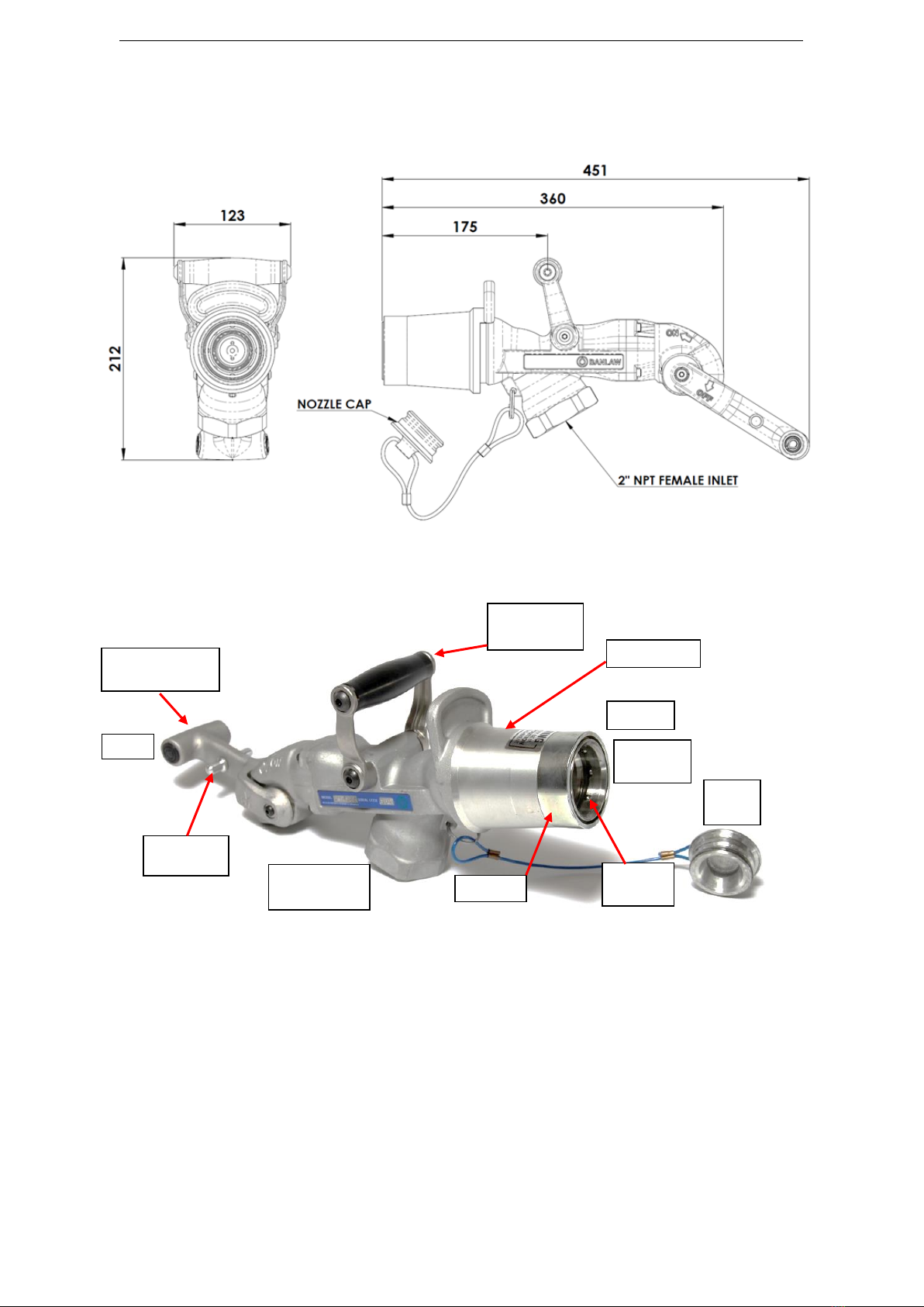
3PRODUCT SPECIFICATIONS .......................................................................................................................................................................13
3.1 Nozzle Flow Performance...................................................................................................................................................................... 14
4INSTALLATION & COMMISSIONING GUIDELINES .....................................................................................................................................15
4.1 Pre-Installation Guidelines..................................................................................................................................................................... 15
4.1.1 Nozzle –Ergonomics....................................................................................................................................................................16
4.1.2 Nozzle –Storage..........................................................................................................................................................................18
4.2 Installation Guidelines ........................................................................................................................................................................... 19
4.2.1 Banlaw FuelTrack Nozzles ...........................................................................................................................................................20
4.3 Commissioning Guidelines..................................................................................................................................................................... 21
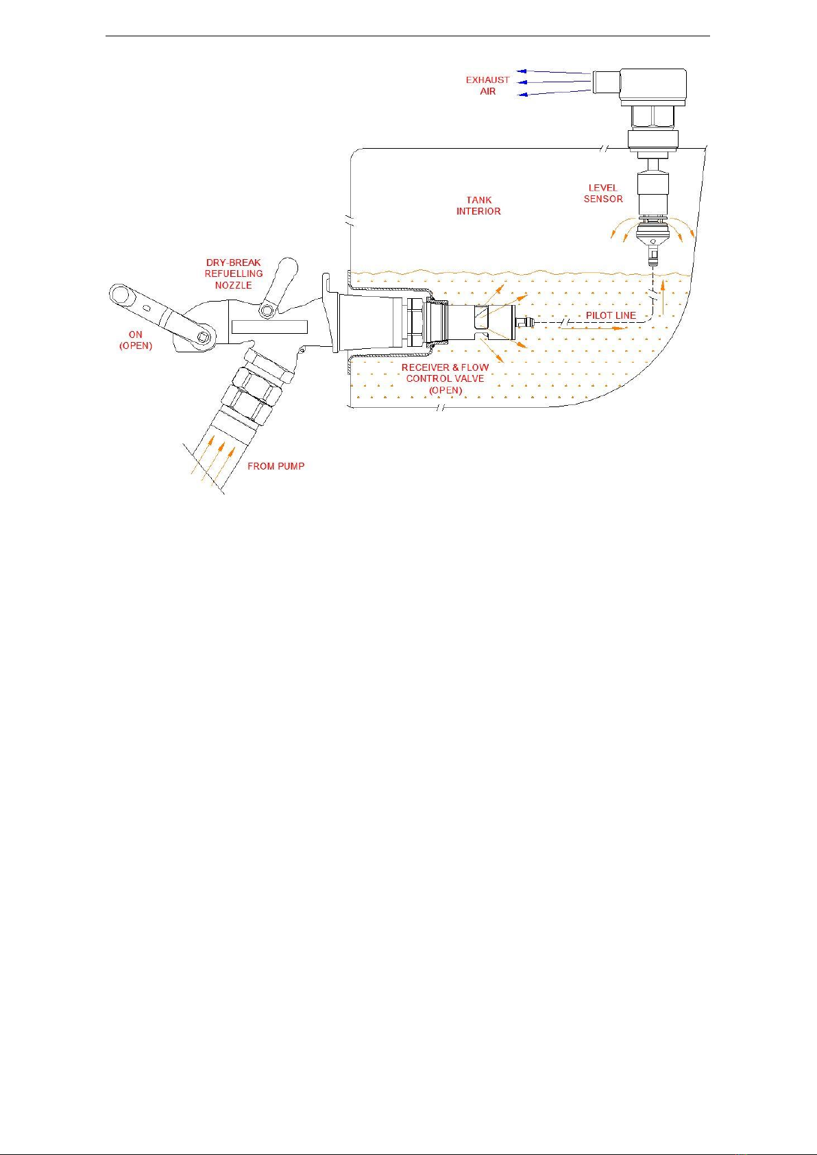
5PRINCIPLES OF OPERATION ......................................................................................................................................................................21
6MAINTENANCE & SPARE PARTS................................................................................................................................................................26
6.1 Preventative Maintenance .................................................................................................................................................................... 26
6.2 Banlaw Onsite Maintenance..................................................................................................................................................................28
7TROUBLESHOOTING..................................................................................................................................................................................29
8PRODUCT RECYCLING & DISPOSAL...........................................................................................................................................................31
9PRODUCT WARRANTY...............................................................................................................................................................................31

BANLAW PRODUCT DATA SHEET DRY-BREAK DIESEL REFUELLING NOZZLES
Doc ID: PRH-REF-70 Version: 7.0 Page 3of 32
Please ensure you have the latest version of this document.
1.1 Glossary of Terms
The following glossary defines key terms used within this document.
Dry-Break
An industry term used to describe a fluid coupling which is of the “normally closed”
or liquid tight state whilst ever this coupling remains disconnected from its mating
coupling. Fluid (fuel) pressure may exist within the coupling, although no fluid
discharge may occur whilst the coupling remains in the normally closed (dry-break)
state.
Nozzle
A female refuelling coupling (coupler) –sometimes referred to as a “fuel gun” -
normally attached to the end of the dispensing (supply) line (e.g. dispensing hose).
A Nozzle engages with a Receiver to form a sealed (liquid-tight) connection for the
pressurised transfer of a liquid (e.g. diesel).
Receiver
A male refuelling coupling (coupler), normally attached to the inlet of the vessel to
be filled via the Nozzle.
Tank Vent
For the purposes (scope) of this document, a Tank Vent (or Vent) shall refer to a
Banlaw Vent (or Vent of same kind) specifically designed to be compatible with the
Banlaw quick-fill refuelling system.
Quick-Fill
An industry term used to describe a complete dry-break diesel refuelling system,
consisting of a Nozzle, Receiver and Tank Vent(s). This system is the same kind as
the Banlaw refuelling system, specifically a system which relies on the closure of
the Tank Vent(s) once the Tank(s) is refilled, the short-term pressurisation of the
Tank(s), and the automatic shut-off (i.e. closure) of the Nozzle.
Overfill
Protection
(OFP)
Refers to a system designed to supplement (complement) a Quick-Fill System, but
where the OFP system acts as the primary (first) means of terminating the inflow
of liquid into the tank without the need for pressurisation of the tank(s).
Flash Point (FP)
“The lowest temperature, corrected to a barometric pressure of 101.3kPa(a) (i.e.
1 atm), at which application of a test flame causes the vapour of the test portion
to ignite under the specified conditions of the test.” [AS1940-2004].
Combustible
Substance
(Liquid)
“Any liquid, other than a Flammable Liquid, that has a Flash Point, and has a Fire
Point that is less than its Boiling Point.” [AS1940-2004]. Other definitions denote a
combustible liquid as having a Flash Point of >60.5°C (>140.9°F). In addition;
“Combustible liquids that are stored, handled or processed at a temperature T ≥
(FP−6°C) should be considered as flammable liquids. Zonal (hazardous area)
distances for such liquids should be determined accordingly in accordance with
this Standard unless a detailed classification indicates otherwise.” [AS/NZS
60079.10.1-2009 ZA.5].
Flammable
Substance
(Liquid)
“Liquids, or mixtures of liquids, or liquids containing solids in solution or
suspension which give off a flammable vapour at temperatures of not more than
60.5°C (140.9°F), closed cup test, or not more than 65.6°C (150.1°F), open cup test,
normally referred to as the Flash Point.” [AS1940-2004]. In addition; “Combustible
liquids that are stored, handled or processed at a temperature T ≥ (FP−6°C)
should be considered as flammable liquids.
Diesel Fuel
Clean (filtered) automotive grade diesel fuels, including summer and winter
blends. Excludes heavy distillates, e.g. bunker oils, heavy fuel oils (HFO), etc.
Explosive
Atmosphere
“Mixture with air, under atmospheric conditions, of flammable substances in the
form of gas, vapour, dust, fibres, or flyings which, after ignition, permits self-
sustaining flame propagation.” [AS/NZS 60079.10.1-2009].

BANLAW PRODUCT DATA SHEET DRY-BREAK DIESEL REFUELLING NOZZLES
Doc ID: PRH-REF-70 Version: 7.0 Page 4of 32
Please ensure you have the latest version of this document.
Hazardous Zone
“An area in which an Explosive Atmosphere is or may expected to be present, in
quantities such as to require special precautions for the construction, installation
and use of equipment.” [AS/NZS 60079.10.1-2009]. The classification of a
Hazardous Zone is conducted in accordance with the governing Standards –
typically specific to regions/countries, in the absence of universal (harmonised)
Standards.
Spring Setting
Within this document “spring setting” applies to the setting of the automatic shut-
off (closure) feature of a Nozzle. This feature is responsive to liquid (i.e. diesel)
pressure within the Nozzle and can be adjusted by changing the specification of
the Piston Spring within the Nozzle and/or the specification of the Poppet Spring
within the Receiver. In simple terms, increasing the spring setting will increase the
liquid pressure at which the Nozzle will automatically shut-off, and decreasing the
spring setting will decrease the pressure required for shut-off.
1.2 System Overview
Banlaw Dry-Break Diesel Refuelling Nozzles are a key component used in “quick-fill” refuelling systems.
Banlaw Nozzles provide a means of fuel shut-off and are often used in systems incorporating storage
tank Overfill Protection (e.g. Banlaw FillSafe™Zero, FillSafe Power) and fluid asset management systems
(i.e. Banlaw FuelTrack™ Banlaw ResTrack™).
Figure 2 –Example of a “Pressurised Tank”Refuelling System
The example shown in Figure 2 is a basic “quick-fill” tank refuelling system incorporating Banlaw Nozzle,
Receiver, and Tank Vent. The means of fuel flow shut-off in such systems is by closure of the Vent,
(internal) pressurisation of the tank, and automatic shut-off (closure) of the Nozzle. Incorporating a
Banlaw FuelTrack Receiver provides a means of identifying the unique asset “tag” (code) of the tank
within the FuelTrack or ResTrack system.
The example shown in Figure 3 is a refuelling system using a separate means of tank OFP –specifically
a Banlaw FillSafe™Zero system. In this example, the Banlaw “pressurised tank” system acts as a backup
in the unlikely event the primary OFP fails.

BANLAW PRODUCT DATA SHEET DRY-BREAK DIESEL REFUELLING NOZZLES
Doc ID: PRH-REF-70 Version: 7.0 Page 5of 32
Please ensure you have the latest version of this document.
Figure 3 –Example of a “Pressurised Tank” Refuelling System with Separate OFP
1.3 Key Features
Since their inception, Banlaw refuelling nozzles have evolved as a key part of Banlaw’s commitment to
innovation and continuous improvement. Considered a market leader, Banlaw nozzles provide industry-
leading standards of safety, reliability, durability and serviceability. Designed to provide an extended
service life, some of the earliest generation of Banlaw nozzles are still being serviced and returned into
operation!
Key advantages of Banlaw nozzles include;
•Patented means of adjusting the automatic shut-off (closure) setting, accommodating a wider
variety of refuelling applications.
•Banlaw 800 model “Mining” series Nozzles (e.g. BNM800M) suit all industry standard Receivers,
e.g. Wiggins ZN2 & JNX series, Caterpillar, FloMAX FR series, etc.
•Industry-proven ball lock latching mechanism, providing superior safety and durability.
•Wearing and structural parts manufactured from metals, not plastic.
•Parts manufactured from stainless steel for superior durability.
•Serviceable by accredited (trained) Nozzle Repair Agents in most regions and countries.
•“Arctic” (cold temperature) models available for safe and reliable operation in extreme cold
climates.
•High quality OEM fluid seals used in all dynamic sealing applications, not inexpensive O’Rings.
•Manufactured, assembled and factory tested in accordance with Banlaw’s ISO9001 certification.
Every nozzle is traceable by its serial code.
•Banlaw FuelTrack™ models available to support the automatic identification (auto ID)
functionality of a Banlaw FuelTrack or ResTrack system –arguably the most secure fuels and
resource management system of its kind available in the market.

BANLAW PRODUCT DATA SHEET DRY-BREAK DIESEL REFUELLING NOZZLES
Doc ID: PRH-REF-70 Version: 7.0 Page 6of 32
Please ensure you have the latest version of this document.
Figure 4 illustrates the overall dimensions (millimetres, mm) of a Banlaw refuelling nozzle;
Conversion; 1mm ≈ 0.039”, i.e. 25.4mm = 1”.
Figure 4 - Overall Dimensions of an 800 Series Banlaw Refuelling Nozzle
Figure 5 illustrates the key external features of a Banlaw refuelling nozzle.
Figure 5 - Key External Features of Banlaw Nozzle
1.4 Part Numbering
Figure 6 and Figure 7 denotes the part numbering system used for Banlaw nozzles currently available.
Earlier (superseded) Banlaw nozzles were assigned a different part number –if required, please contact
Banlaw for details. Refer to section 1.6 for important information on Nozzle Spring Settings.
OPERATING “T”
HANDLE
CARRY “D”
HANDLE
ACTUATOR
DUST
PLUG
HANDLE
CATCH
NOZZLE INLET
2” NPT (F)
NOZZLE
OUTLET
FRONT
REAR
BUMPER
BALL
LOCKS

BANLAW PRODUCT DATA SHEET DRY-BREAK DIESEL REFUELLING NOZZLES
Doc ID: PRH-REF-70 Version: 7.0 Page 7of 32
Please ensure you have the latest version of this document.
Figure 6 - 800 Series Nozzle Part Numbering
Figure 7 - 1000 Series Nozzle Part Numbering
1.5 Available Nozzle Models
The 800 Nozzle series currently consists of 12 different models, whilst the 1000 Nozzle series consists
of 4 models –as per Table 1. Please refer to Banlaw Sales & Marketing material for further details.
800 Series
1000 Series
Standard
FuelTrack
Standard
FuelTrack
BNM800
BNMF800
BN1000
BNF1000
BNM800-CT
BNMF800-CT
BN1000-CT
BNF1000-CT
BNR800
BNRF800
BNR800-CT
BNRF800-CT
BNH800
BNHF800
BNH800-CT
BNHF800-CT
Table 1 - Nozzle Models

BANLAW PRODUCT DATA SHEET DRY-BREAK DIESEL REFUELLING NOZZLES
Doc ID: PRH-REF-70 Version: 7.0 Page 8of 32
Please ensure you have the latest version of this document.
NOTES: 1. Not all Models are available ex-stock and are made to order.
2. Each Model is available with select spring (i.e. shut-off pressure) settings. Not every spring
setting is available in each Model.
3. Nozzle availability is subject to change –please refer to the Banlaw website or contact Banlaw
or your nearest authorised Banlaw distributor for the most up to date details.
Figure 8 illustrates the location on a Nozzle where the model and unique serial code details are marked.
Figure 8 –Example of Model and Serial Details on Right Side of Nozzle
1.6 Nozzle Spring Settings
Each Nozzle is available with a pre-set spring setting, specifically the setting (specification) of the piston
spring. Banlaw document EBL-33 provides further important information on spring settings.
Selection of the required Spring Setting should be performed prior to purchase of a
Nozzle. Any adjustment of the Spring Setting within a Nozzle must only be
conducted by Banlaw or a Banlaw authorised Nozzle Repair Agent. The use of a
Nozzle with an inappropriate Spring Setting is potentially unsafe, and likely to
increase the risk level of hazards such as:
•Overfilling of the tank(s).
•Internal over-pressurisation of the tank(s).
•Fuel spillage.
•Personal injury, fire, or explosion.
Please conduct Banlaw for information on Nozzle Spring Settings.
“IF IN DOUBT, ASK!”
Available spring settings are detailed within Table 2.
Shut-Off (Spring) Setting
Nozzle Series
Setting
Code/Marking
800 Series
1000 Series
Light
L
Medium-Light
ML
Medium
M
Medium-Heavy
MH
Heavy
H
Extra-Heavy
XH
Table 2 - Available Nozzle Shut-Off (Spring) Settings
Table 2 Legend: Yes (available) No (unavailable)

BANLAW PRODUCT DATA SHEET DRY-BREAK DIESEL REFUELLING NOZZLES
Doc ID: PRH-REF-70 Version: 7.0 Page 9of 32
Please ensure you have the latest version of this document.
Figure 9 is a simplified diagram illustrating the interface between the nozzle and receiver during
refuelling and the forces involved in opening or closing the nozzle.
Figure 9 - Simplified General Arrangement of Nozzle and Receiver Interface
Figure 10 provides a basic illustration of the relationship between Nozzle and Receiver spring settings.
Figure 10 - Relationship Between Nozzle and Receiver Spring Settings
Figure 11 illustrates the location on a Nozzle where the Spring Setting is marked.
Figure 11 - Example of Spring Setting Marking on Top of Nozzle
For a given Nozzle spring setting, the effective (actual) liquid pressure at which the automatic shut-off
mechanism of a Nozzle is activated is dependent on several factors, including;
•Spring setting of the Receiver onto which the Nozzle is connected.
•Make (OEM) of Receiver.
•Liquid flowrate.
•The working condition of the Nozzle, i.e. whether the Nozzle is operating within the applicable
specifications for an “as new” (i.e. compliant) Nozzle.
“M”
(MEDIUM)

BANLAW PRODUCT DATA SHEET DRY-BREAK DIESEL REFUELLING NOZZLES
Doc ID: PRH-REF-70 Version: 7.0 Page 10 of 32
Please ensure you have the latest version of this document.
Table 3 details the relationship between the various Nozzle settings, specifically with respect to the
“Medium” (M) setting. I.e. the “offset” refers to the change in nozzle shut-off pressure from a Medium
setting. This data only applies when the Banlaw Nozzle is used with a Banlaw Receiver and the Receiver
spring setting remains unchanged. The data may be subject to change when a nozzle is used with a non-
Banlaw (third party) receiver.
Nozzle Spring Setting
Code/Marking
Nozzle Shut-Off Pressure Offset (± 5 kPa)
Light
L
-40 kPa (5.8psi)
Medium-Light
ML
-20kPa (2.9psi)
Medium (Standard)
M
0 kPa
Medium-Heavy
MH
+10 kPa (1.5psi)
Heavy
H
+25 kPa (3.6psi)
Table 3 - Nozzle (Piston Spring) Shut-Off Settings
Examples;
•Adjusting the Nozzle spring setting from a Medium (M) to a Light (L) setting will decrease the
shut-off pressure by 40 ± 5 kPa.
•Adjusting the Nozzle spring setting from a Medium (M) to a Heavy (H) setting will increase the
shut-off pressure by 25 ± 5 kPa.
Please refer to the Product Data Sheet (PRH-REF-72) for information on Receiver spring settings.
1.7 FuelTrack Nozzle Variants
Figure 12 illustrates the basic architecture of the Banlaw FuelTrack dry-break auto ID system, specifically
the Nozzle and Receiver in the 2 operating states;
•Nozzle disconnected from Receiver;
o4.6 to 5Vdc at the centre contact of the Nozzle.
oReceiver is passive.
oNo auto ID circuit.
•Nozzle connected to Receiver;
oAuto ID circuit energised between Nozzle and Receiver.
oCircuit “reads” unique ID tag (code) of Receiver. The Signal from the auto ID circuit is
transmitted through the active data cable and is Received and processed by the Local
Controller (i.e. “Depot”).
Most refuelling applications utilising a Banlaw or similar Nozzle are accommodated
using a “Medium” (M) spring setting, however growing use of larger plant equipment
and higher refuelling flowrates is creating a requirement for heavier (higher) Nozzle
spring settings. In addition, the use of non-metal (i.e. plastic, resin) fuel tanks are often
best refilled using a lighter Nozzle spring setting. Please refer document EBL-33.
To provide the highest practicable level of protection, Banlaw recommends a suitable
zero pressure overfill protection (OFP) system –e.g. Banlaw FillSafe™ is considered
for all tanks.

BANLAW PRODUCT DATA SHEET DRY-BREAK DIESEL REFUELLING NOZZLES
Doc ID: PRH-REF-70 Version: 7.0 Page 11 of 32
Please ensure you have the latest version of this document.
Figure 12 - Basic Operation of the Banlaw Dry-Break Auto ID System
1.8 Nozzle and Receiver Compatibility
Table 4 details the cross-compatibility of Banlaw Nozzles and the various Receivers available.
BANLAW NOZZLE & RECEIVER COMPATIBILITY
Nozzles Series
Receivers Series
Banlaw 800 “Mining”
Banlaw 23 “Mining”
Wiggins ZN2, JNC2, JNX, etc.
Caterpillar
FloMAX International FR, FRA, FRS, etc.
Fast Fill Systems R150, R150CV, etc.
# See also Note 1 (below)
Banlaw FuelTrack 800 “Mining”
Banlaw FuelTrack 23 “Mining”
# See also Note 2 (below)
Banlaw 800 “Rail”
Banlaw 23 “Rail”
Banlaw FuelTrack 800 “Rail”
Banlaw FuelTrack 23 “Rail”
Banlaw 800 “Hydraulic”
Banlaw 23 “Hydraulic”
Banlaw FuelTrack 800 “Hydraulic”
Banlaw FuelTrack 23 “Hydraulic”
Banlaw 1000
Banlaw 43
Banlaw FuelTrack 1000
Banlaw FuelTrack 43
Table 4 - Banlaw Nozzle and Receiver Compatibility

BANLAW PRODUCT DATA SHEET DRY-BREAK DIESEL REFUELLING NOZZLES
Doc ID: PRH-REF-70 Version: 7.0 Page 12 of 32
Please ensure you have the latest version of this document.
NOTES: 1. Receiver OEM’s and Part Numbers subject to change. Banlaw 800 “Mining” series Nozzles will
also suit Receivers of the same type (basic design) manufactured by OEM’s not listed.
2. Banlaw FuelTrack 800 “Mining” series Nozzles will suit Receivers compatible with the Banlaw
800 “Mining” series Nozzles, however the automatic identification (auto ID) feature of the
FuelTrack (or Banlaw ResTrack) system will be inoperable.
3. The use of a Nozzle and Receiver combination deemed as incompatible is not condoned by
Banlaw and will create potentially serious safety and environmental hazards.
4. Applications where a Banlaw Nozzle is used with a non-Banlaw (i.e. third party) Receiver will
be subject to (i.e. governed by) specifications contrary to those of the Banlaw Nozzle –as per
section 3. In all such cases;
a. Minimum specification (lower threshold or limit); the highest specification nominated
by Banlaw or the Receiver OEM shall apply.
b. Maximum specification (upper threshold or limit); the lowest specification nominated
by Banlaw or the Receiver OEM shall apply.
2IMPORTANT RESTRICTIONS ON THE USE OF THIS PRODUCT
1. The safe installation and subsequent operation of a Banlaw product relies on the
completion of all necessary “due diligences” for the assessment of the Banlaw
product(s) being suitable for the intended application(s). Such an assessment is
best achieved through the cooperation of the supplier/OEM (Banlaw) and the
customer or end-user. Once such an assessment deems the Banlaw product(s)
to be suitable, the customer or end-user shall ensure effective “change
management” applies should any prominent or influential aspect of the
application (upon which the initial assessment was based) be subject to change
and may affect the ongoing suitability (i.e. safety and proper function) of the
Banlaw product.
2. These Banlaw Dry-Break Refuelling Nozzles incorporate external and internal
components manufactured from aluminium. Products containing external
(exposed) aluminium are typically unsuitable for use within an underground
coal mine, or otherwise within an area where the use of external aluminium
components (or other materials within the product) are prohibited for use in
such areas in accordance with applicable governances.
1. During October 2010 Banlaw conducted a self-assessment (Banlaw document
EBL-19) of the Banlaw dry-break diesel refuelling Nozzles (and mating Banlaw
Receivers) under the requirements of the European Union (EU) Pressure
Equipment Directive (PED) 97/23/EC. The outcome of this assessment was that
these products do not require the CE mark when used in accordance with the
Banlaw product specifications. Unless noted otherwise by Banlaw, this product
has not been assessed under any other Regulatory or Industry Standard, Code,
Directive, Guideline or other governance which may apply to the use of this
product in applications where a governance applies. Please consult Banlaw prior
to installation if in doubt.
2. Please refer to Table 4 for details of compatibility of Banlaw Nozzles with Banlaw
and non-Banlaw Receivers. The use of a Nozzle and Receiver combination

BANLAW PRODUCT DATA SHEET DRY-BREAK DIESEL REFUELLING NOZZLES
Doc ID: PRH-REF-70 Version: 7.0 Page 13 of 32
Please ensure you have the latest version of this document.
deemed as incompatible is not condoned by Banlaw and will create potentially
serious safety and environmental hazards.
3. Banlaw Dry-Break Refuelling Nozzles are designed and tested for use with clean
(i.e. filtered) automotive grade diesel fuels, including commercial bio-diesel
blends. This Banlaw product is not recommended for use with waste diesel fuel,
or with diesel fuel containing contamination levels beyond those stipulated by
governances and guidelines such as the current Worldwide Fuel Charter (WWFC)
and fuel quality requirements of modern diesel engine manufacturers. The use
of this product with fuel of higher contamination levels may cause the improper
operation (failure) of the product and other detrimental effects. Banlaw
recommends adequate fuel contamination controls (e.g. filtration) for all fuels
passing through a Banlaw Nozzle;
a. The use of a Banlaw Nozzle with an alternate liquid type –e.g. a light oil
–may be conditionally acceptable after consultation with Banlaw.
b. Banlaw “Hydraulic” Nozzles (i.e. BNH800 series) have traditionally been
used with solcenic oils without incident.
4. Banlaw Nozzles are not recommended for use with AdBlue, corrosive, oxidizing,
acids, alkaline, solvents, flammable, explosive or gaseous (compressible) fluids or
with an alternative fluid (or substance) whose properties may affect the safety,
function or reliability of the product.
5. Specifically, for “Arctic” series Nozzles, noticeable physical changes (e.g.
clouding, additive drop-out, agglomeration, thickening, etc.) in the diesel fuel
passing through a Nozzle may cause reduced functionality of the Nozzle (and
associated Refuelling system).
3PRODUCT SPECIFICATIONS
BANLAW 800 MODEL NOZZLES
Max. Diesel Flow Rate LPM
(GPM)
800LPM (211GPM)
Min. Flow Rate LPM (GPM)
90LPM (24GPM)
Operating Temp. Range °C (°F)
-10°C (14 °F) to 55°C (131°F)
“Arctic” (-CT) series; -51°C (-60°F) to 55°C (131°F)
Max. Internal SWP kPa (psi)
Non-FuelTrack Nozzles: 2,000kPa (290psi)
FuelTrack Nozzles: 1,000kPa (145psi)
Compatible Fluid Types
Clean (filtered) Automotive Diesel Fuels, incl. Bio-Diesel
Blends. Refer also section 2.
Principal Material Composition
Aluminium, Brass, Stainless Steel, Zinc Plated Steel, Viton®,
Nitrile (NBR), Acetal, Fluorosilicone, Nylon
Process Connection (Inlet)
2” NPT (F)
Mass of Nozzle (approx.)
3.9kg (8.6lb)

BANLAW PRODUCT DATA SHEET DRY-BREAK DIESEL REFUELLING NOZZLES
Doc ID: PRH-REF-70 Version: 7.0 Page 14 of 32
Please ensure you have the latest version of this document.
BANLAW 1000 MODEL NOZZLES
Max. Diesel Flow Rate LPM (GPM)
1,000LPM (264GPM)
Min. Flow Rate LPM (GPM)
400LPM (106GPM)
Operating Temp. Range °C (°F)
-10°C (14 °F) to 55°C (131°F)
“Arctic” (-CT) series; -51°C (-60°F) to 55°C (131°F)
Max. Internal SWP kPa (psi)
Non-FuelTrack Nozzles: 2,000kPa (290psi)
FuelTrack Nozzles: 1,000kPa (145psi)
Compatible Fluid Types
Clean (filtered) Automotive Diesel Fuels, incl. Bio-
Diesel Blends
Refer also section 2.
Principal Material Composition
Aluminium, Brass, Stainless Steel, Zinc Plated Steel,
Viton®, Nitrile (NBR), Acetal, Fluorosilicone, Nylon
Process Connection (Inlet)
2” NPT (F)
Mass of Nozzle (approx.)
4.2kg (9.3lb)
Legend: “SWP”; Maximum recommended Safe Working Pressure
“LPM”; Litres per minute (volumetric flowrate)
“GPM”; US Gallons per minute (volumetric flowrate)
“Max.”; Maximum (upper limit)
“Min.”; Minimum (lower limit)
Notes: 1. All pressure data refers to the internal fluid pressure, where each product is in “as new”
condition.
2. The core function of “Arctic” (CT) series Nozzles (and Banlaw Receivers) has been tested in an
independent laboratory at -51°C (-60°F) under the guidelines of MIL-STD-810G. These Nozzles
are fitted with fluid seals rated for operation below -60°C (-76°F).
3.1 Nozzle Flow Performance
Figure 13 illustrates the dynamic pressure drop (i.e. fluid head loss) through a Banlaw 800 model Nozzle
and Banlaw 23 model Receiver –refer also Notes below.

BANLAW PRODUCT DATA SHEET DRY-BREAK DIESEL REFUELLING NOZZLES
Doc ID: PRH-REF-70 Version: 7.0 Page 15 of 32
Please ensure you have the latest version of this document.
Figure 13 - Pressure Drop Through 800 Nozzle and 23 Receiver
Figure 14 illustrates the dynamic pressure drop (i.e. fluid head loss) through a Banlaw 1000 model Nozzle
and Banlaw 43 model Receiver –refer also Notes below.
Figure 14 - Pressure Drop Through 1000 Nozzle and 43 Receiver
Notes: 1. All pressure drop data refers to the dynamic head loss through the Banlaw Nozzle and Banlaw
Receiver combination. This data will vary when a Banlaw Nozzle is used with a non-Banlaw
Receiver.
2. All data obtained using automotive grade diesel fuel at approx. 25°C (77°F). If comparing this
Banlaw data with other Nozzle OEM pressure drop data, ensure the fluid properties (density
and viscosity) are comparable with diesel fuel.
3. Data measured by flowrate and pressure measurement equipment calibrated in accordance
with Banlaw’s ISO 9001 certification.

BANLAW PRODUCT DATA SHEET DRY-BREAK DIESEL REFUELLING NOZZLES
Doc ID: PRH-REF-70 Version: 7.0 Page 16 of 32
Please ensure you have the latest version of this document.
4INSTALLATION & COMMISSIONING GUIDELINES
This Installation & Commissioning Guide is general and is not meant to replace or override installation
guidelines that arise out of a due diligence assessment of a Banlaw product for a specific (intended)
application.
The scope of this section applies to this Nozzle, e.g. BNM800M, etc. Where other products are
mentioned –e.g. Receivers, Swivels, Break-Away Valves –end-users must refer to separate Banlaw
documentation covering each product prior to their installation.
4.1 Pre-Installation Guidelines
•Any proposed installation/application/operation of the Banlaw Nozzle shall
satisfy the Specifications detailed in section 3, and other requirements within
this document. As diesel refuelling is typically conducted at elevated pressure
and flowrates, the specifications for any other parts & equipment included
within this install must also comply with the parameters (e.g. pressure,
temperature, flowrate, etc.) of the application. Failure to ensure the Nozzle
and other equipment are used strictly in accordance with their applicable
specifications will introduce potentially serious safety hazards.
•Ensure a Nozzle with the correct Shut-Off Setting (refer section 1.6) is being
installed. Failure to select the proper nozzle setting will increase the risk of
hazards such as;
oOverfilling and the likely internal over-pressurisation of the tank(s).
oSpillage of fuel, environmental damage, or fire.
oPremature shut-off of the Nozzle, i.e. automatic shut-off of the Nozzle
before the tank is filled.
•This Product shall only be used by competent persons, trained and/or directly
supervised in their safe and proper operation.
•The Nozzle and all other diesel dispensing and refuelling system pressure
equipment shall be rated for the process conditions, i.e. pressure, flowrate
and temperature. In the event of a “drive-away” all components –i.e. the
Nozzle, Receiver, tank inlet and diesel dispensing system - shall be subjected
to abnormally high structural load (forces) which may cause catastrophic
failure of equipment within the system and potentially serious health, safety
and environmental hazards. The consequences of a drive-away can be
reduced using a sacrificial mechanical link within the system, e.g. a Banlaw
Break-Away Valve.
4.1.1 Nozzle –Ergonomics
When designing the refuelling system, the ergonomics of the nozzle operation must
be considered to avoid potentially serious work health & safety (WHS) hazards. An
assessment of the physical handling of the Nozzle for each intended application must
be part of a pre-installation due diligence assessment. Key manual handling tasks
include;
•Carrying the Nozzle and attached fuel supply line to and from the Nozzle
storage point (e.g. Nozzle Holster) and the Receiver onboard the plant
equipment.

BANLAW PRODUCT DATA SHEET DRY-BREAK DIESEL REFUELLING NOZZLES
Doc ID: PRH-REF-70 Version: 7.0 Page 17 of 32
Please ensure you have the latest version of this document.
•Connection and disconnection of the Nozzle and Receiver, particularly at
extended reach.
•Actuation of the Nozzle operating handle, particularly at extended reach.
Additionally, to prevent damage and contaminant ingress, Nozzles should not be
dragged on the ground. This type of Nozzle abuse is particularly common in
applications that incorporate hose reels with an automatic rewind function.
The use of a Banlaw Swivel at the Nozzle inlet is recommended to improve ergonomics, specifically to
reduce the degree of twist transferred to the Nozzle from the attached supply hose –refer Figure 15.
Figure 15 –Basic Nozzle and Receiver Arrangement
•The Nozzle must be aligned concentrically with the Receiver for connection.
•The Nozzle may be oriented at any angle during operation –i.e. when
connected to the Receiver.
•To improve ease of use (ergonomics);
oIf the Receiver is installed at a height above (human) chest height (i.e.
above approx. 1.2m, 4’), end-users may benefit from the installation
of the Receiver in a downwards orientation –as per Figure 16.
oIf the Receiver is installed at a height below (human) waist height (i.e.
below approx. 0.9m, 3’), end-users may benefit from the installation
of the Receiver in an upwards orientation –as per Figure 17.
•The overall weight of the Nozzle and attached hose and fittings should be
minimised. This objective is aided by avoiding the use of excessive fittings
between the hose outlet and nozzle inlet. The hose outlet should be
configured to attach directly into the Swivel inlet.
NOZZLE
RECEIVER
SWIVEL
FROM
SUPPLY
TO TANK

BANLAW PRODUCT DATA SHEET DRY-BREAK DIESEL REFUELLING NOZZLES
Doc ID: PRH-REF-70 Version: 7.0 Page 18 of 32
Please ensure you have the latest version of this document.
Figure 16 - Angled (Down) Orientation of Receiver
Figure 17 - Angled (Up) Orientation of Receiver
4.1.2 Nozzle –Storage
A secure means of storing the Nozzle when not in use must be provided to avoid situations where the
Nozzle is left lying on the ground, increasing the risk of contamination ingress into the Nozzle and a
potential trip hazard to personnel. This can be accomplished by installing a Banlaw Nozzle Holster or
Nozzle Anchor or by fabricating a custom bracket to safely store the Nozzle. The location of the holster
etc. shall allow safe, convenient and ergonomic access by personnel, and provide a means of stowing
the nozzle and dispensing hose in a safe location out of pedestrian and vehicle thoroughfares.
Additionally, use of a dedicated storage point be interlocked with additional safety systems to prevent
vehicle driveaway while the nozzle is still connected.
Figure 18 illustrates the use of a (“tall”) Banlaw Nozzle Holster. “Short” holsters (i.e. without the stand)
are also available for mounting onto existing raised platforms and for use on service trucks etc.
RECEIVER INSTALLED
AT ELEVATED HEIGHT
RECEIVER INSTALLED
AT LOW HEIGHT

BANLAW PRODUCT DATA SHEET DRY-BREAK DIESEL REFUELLING NOZZLES
Doc ID: PRH-REF-70 Version: 7.0 Page 19 of 32
Please ensure you have the latest version of this document.
Figure 18 - Nozzle Stored in Nozzle Holster
4.2 Installation Guidelines
A dedicated means of securely storing a Nozzle off the ground provides several key
benefits, including;
•Minimises the ingress of contamination (dust, water, etc.) into the Nozzle -
maximising the service life of the Nozzle.
•Minimises the risk of the Nozzle being struck or run over by vehicles in the
same area. Bollards or barriers around the area will also assist.
•Minimises trip hazards.
•Can be interlocked with additional safety features to prevent vehicle
“driveaway”.
General Installation Notes;
1. Conduct a Job Hazard Analysis (JHA) prior to install to mitigate health,
environmental and equipment hazards.
2. Do NOT install any parts that are damaged or are otherwise faulty.
3. Do NOT install parts which are not compatible with mating parts or parts
which do not satisfy the specifications of the system.
4. Conduct all necessary measures to prevent the ingress of contamination into
the Banlaw Nozzle and other components.
5. Only engage threads of the same thread type. Ensure all threaded connections
are clean and in good condition. Avoid over-tightening.
6. An appropriate thread sealant is recommended on the 2” NPT (F) process
connection (inlet) of the Nozzle. Use sparingly and avoid excess use of Loctite
NOZZLE
HOLSTER

BANLAW PRODUCT DATA SHEET DRY-BREAK DIESEL REFUELLING NOZZLES
Doc ID: PRH-REF-70 Version: 7.0 Page 20 of 32
Please ensure you have the latest version of this document.
Damage to the cast housing of the Nozzle can occur if the 2” NPT (M) fitting (i.e. Swivel outlet) is over-
tightened into the Nozzle inlet. With appropriate thread sealant, the 2” NPT threaded connection
should be tightened to approximately 1.5 to 2 turns (i.e. 5mm, 13/64”) past hand-tight engagement.
I.e. NPT threads are tightened according to the length of thread engagement, not a torque.
Figure 19 - Nozzle Inlet Connected
4.2.1 Banlaw FuelTrack Nozzles
This section applies to installation requirements specifically for FuelTrack series Nozzles –e.g. BNMF800
and BNF1000 series. During connection of the Swivel –refer section 4.2 - it is imperative the spring-
loaded “male” probe extending from the Swivel outlet is inserted into the “female” probe within the
Nozzle inlet.
Figure 20 shows the auto ID circuit components (i.e. hard links) connecting the FuelTrack Swivel to the
FuelTrack Nozzle inlet.
Figure 20 - Swivel Outlet and Nozzle Inlet
and similar products –residual thread sealants etc. may cause contamination
and malfunction of the Nozzle.
7. Use only proper hand tools for the installation of all components. Avoid the
use of power or impact tools, and adjustable wrenches (e.g. stilsons).
8. Use consumables (e.g. Loctite products) strictly in accordance with the OEM
Safety Data Sheet (SDS) and operating guidelines. Do not use consumables
beyond their expiry date.
DO NOT
OVERTIGHTEN
SWIVEL
HOSE-TAIL
INSERT DURING
CONNECTION
This manual suits for next models
17
Table of contents
Other BANLAW Petrol Station Equipment manuals