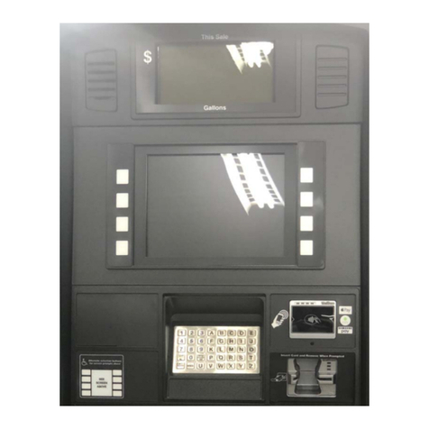
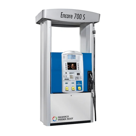
GILBARCO VEEDER-ROOT Encore 300 Series User manual

Encore®
Installation Manual
MDE-3985L

Computer Programs and Documentation
All Gilbarco Inc. computer programs (including software on diskettes and within memory chips) and documentation are copyrighted by, and shall remain the property of, Gilbarco
Inc. Such computer programs and documents may also contain trade secret information. The duplication, disclosure, modification, or unauthorized use of computer programs or
documentation is strictly prohibited, unless otherwise licensed by Gilbarco Inc.
Federal Communications Commission (FCC) Warning
This equipment has been tested and found to comply with the limits for a Class A digital device pursuant to Part 15 of the FCC Rules. These limits are designed to provide
reasonable protection against harmful interference when the equipment is operated in a commercial environment. This equipment generates, uses, and can radiate radio frequency
energy, and if not installed and used in accordance with the instruction manual, may cause harmful interference to radio communications. Operation of this equipment in a
residential area is likely to cause harmful interference in which case the user will be required to correct the interference at his own expense. Changes or modifications not expressly
approved by the manufacturer could void the users authority to operate this equipment.
Approvals
Patents
Gilbarco Inc. products are manufactured or sold under one or more of the following US patents:
Dispensers
Point of Sale/Back Office Equipment
Trademarks
4,566,504 4,556,927 4,570,686 4,687,033 4,728,788 4,748,846 4,799,940 4,805,453 4,876,653 4,890,210 4,913,813 4,930,655 4,934,565 4,938,054
4,938,251 4,939,730 4,967,366 4,986,445 5,040,577 5,098,179 5,134,548 5,156,199 5,269,353 5,228,084 5,325,706 5,345,979 5,355,915 5,363,988
5,384,850 5,407,115 5,417,256 5,448,638 5,450,883 5,464,466 5,501,246 5,535,130 5,542,458 5,543,849 5,546,981 5,557,084 5,571,310 5,602,745
5,626,649 5,630,528 5,708,580 5,719,779 5,719,781 5,720,325 5,724,067 5,734,851 5,755,854 5,782,275 5,794,667 5,798,931 5,803,136 5,843,212
5,857,500 5,868,179 5,871,651 5,890,520 5,954,080 5,956,259 5,969,691 5,971,042 5,979,705 5,980,090 6,026,866 6,052,629 6,073,840 6,078,888
6,078,896 6,082,415 6,085,775 6,087,954 6,089,284 6,092,410 6,098,879 6,102,085 6,109,477 6,112,134 6,113,039 6,116,505 6,119,110 6,123,118
6,149,033 6,167,923 6,176,421 6,184,846 6,185,307 6,185,893 6,196,065 6,227,227 6,244,310 6,250,151 6,253,779 6,263,319 6,275,746 6,296,148
6,302,165 6,313,737 6,325,112 6,326,934 6,336,479 6,338,369 6,347,649 6,352,176 6,357,493 6,360,137 6,363,299 6,364,206 6,380,853 6,381,514
6,386,246 6,418,983 6,421,616 6,422,464 6,431,226 6,438,452 6,460,579 6,463,389 6,466,842 6,470,233 6,493,440 6,499,516 6,505,134 6,522,947
6,523,744 6,529,800 6,532,999 6,535,726 6,546,882 6,571,151 6,571,201 6,573,884 6,574,603 6,578,145 6,618,362 6,644,360 6,681,814 6,685,089
6,690,275 6,697,705 6,704,774 6,708,797 6,710,701 6,712,101 6,721,669 6,736,313 6,741,909 6,745,104 6,761,190 6,763,974 6,766,949 RE35,238
D262,971 D265,092 D306,719 D309,144 D316,471 D413,124 D413,311 D413,336 D413,337 D413,610 D413,901 D413,902 D414,192 D414,501
D414,778 D414,779 D414,780 D414,781 D414,782 D415,166 D415,167 D415,168 D415,169 D415,170 D415,171 D415,172 D415,501 D415,777
D416,915 D416,916 D417,226 D418,523 D420,684 D421,612 D422,285 D422,604 D426,555 D428,424 D428,897 D429,739 D429,740 D431,039
D431,252 D431,573 D432,140 D432,141 D432,548 D432,552 D433,031 D433,032 D433,033 D433,034 D433,035 D433,036 D433,037 D433,420
D433,421 D433,422 D433,423 D433,424 D433,685 D433,686 D433,687 D433,688 D434,424 D434,780 D435,051 D440,579 D443,624 D456,820
D457,084
4,967,366 5,228,084 5,448,638 5,798,931 5,980,090 5,708,580 5,719,779 5,719,781 5,724,067 5,734,851 6,073,840 6,078,888 6,116,505 6,185,307
6,263,319 6,275,746 6,326,934 6,360,137 6,363,299 6,364,206
Gilbarco is an ISO 9001:2000 registered company.
Underwriters Laboratories (UL):
U L File# Products listed with U L
MH1941 All Gilbarco pumps and dispensers that bear
the UL listing mark.
MH8467 Transac System 1000 and PAM 1000
E105106 Dell DHM Minitower
E165027 G-SITE and Passport Systems
National Conference of Weights and Measures (NCWM) - Certificate of Compliance (CoC):
Gilbarco pumps and dispensers are evaluated by NCWM under the National Type Evaluation Program (NTEP). NCWM has issued the following CoC:
CoC# Product Model # CoC# Product Model # CoC# Product Model #
02-019 Eclipse Exx 02-026 H111B Series AC, RAC 02-034 External Mount CRIND CECXXXXXXX
02-020 Encore Nxx
02-027
MPD-1 Series AN, RAN 02-035 Dimension Dxx
02-021 T-12C Console PA0188, RA0188 Fixed Blender AF, RAF, AG,
RAG 02-036 Legacy Jxxx
T-12C Console PA0203, RA0203 Dispenser - Low Profile AR, RAR
02-037
G-SITE Printer (Epson) PA0307
02-022 T-12G Console PA0180, RA0180 02-028 Indoor Card Q11640 G-SITE Distribution Box PA0306
02-023
T-15 Console PA0189 Outdoor Card Q11891 G-SITE Keyboard PA0304
T-15 Controller C2 PA0211 02-029 CRIND G-SITE Mini Tower PA0301
T-15 Controller PA0190
02-030
TS-1000 Console PA0240 G-SITE Monitor PA0303
02-024
ProBlender AU, RAU TS-1000 Controller PA0241 G-SITE Printer (Citizen) PA0308
Precision Blender AE, RAE Distribution Box PA0242 02-038 C+ Meter T19976
Dispenser - Standard AK, RAK Micro-T Console PA0250 02-039 Passport PA0324
Dispenser - Low Profile AL, RAL Meter - EC Series PA024EC10 02-040 Ecometer T20453
Fixed Blender AP, RAF VaporVac Kits CV
02-025 Meter - C Series PA024NC10 02-031 The Advantage Series Bxx, RBxx
Meter - C Series PA024TC10 02-032 Trimline Series AA, RAA
Salesmaker ProBlender AB, RAB 02-033 Meter - C Series PA024XC10
99-165 Salesmaker Series 2/2H/4/4A AM MPD-A3 Series AD, RAD
New York City Fire Department (NYFD):
NYFD C of A # Product
4805 The Advantage Series and
Legacy Series
4986 Encore and Eclipse
California Air Resources Board (CARB):
Executive Order # Product
G-70-52-AM Balance Vapor Recovery
G-70-150-AE VaporVac
Registered trademarks
CRIND®InfoScreen®Transac® System 1000
Dimension® Series Legacy®Trimline®
e-CRIND®Making Things Better®TRIND®
Eclipse®MPD®VaporVac®
Encore®Passport®
G-SITE®Performer®
Gilbarco®The Advantage® Series
GOLD®Transac®
Additional US and foreign trademarks pending.
Other brand or product names shown may be
trademarks or registered trademarks of their
respective holders.
Non-registered trademarks
C-PAMHighlineSMART Meter
CIMMultiLineSmartPad
ECROptimum Series Surge Management System
EMCPAM 1000 Tank Monitor
G-CATPAMTCR
GilbertSMART ConnectUltra-Hi
G-SITE® LinkSMART CRINDValueLine
G-SITE® LiteSMART Merchandising
This document is subject to change without notice. · For information regarding Gilbarco Inc. Literature, call (336) 547-5661
E-mail: literature@gilbarco.com · Internet: http://www.gilbarco.com
2006 Gilbarco Inc. · All Rights Reserved
Additional US and foreign patents pending.
MDE-3985L Encore® Installation Manual · May 2006 Page i
Table of Contents
Table of Contents
Important Safety Information 1
1 Introduction 5
Purpose of this Manual . . . . . . . . . . . . . . . . . . . . . . . . . . . . . . . . . . . . . . . 5
Encore® Shipping Weight and Model Codes: N-X-X . . . . . . . . . . . . . . . . . 5
Operating Environment . . . . . . . . . . . . . . . . . . . . . . . . . . . . . . . . . . . . . . . 7
Load Table Reference Locations . . . . . . . . . . . . . . . . . . . . . . . . . . . . . . . . 7
Reference Manuals . . . . . . . . . . . . . . . . . . . . . . . . . . . . . . . . . . . . . . . . . . 8
Gaining Access to and from the Encore Cabinet . . . . . . . . . . . . . . . . . . . . 8
Glossary of Terms . . . . . . . . . . . . . . . . . . . . . . . . . . . . . . . . . . . . . . . . . . . 9
2 Hazardous Locations 10
Classifying Hazardous Locations . . . . . . . . . . . . . . . . . . . . . . . . . . . . . . . 10
3 Installation 11
Replacing The Advantage® Series with Encore . . . . . . . . . . . . . . . . . . . . 11
Required Equipment and Materials . . . . . . . . . . . . . . . . . . . . . . . . . . . . . 11
Read NFPA 30A and NFPA 70 . . . . . . . . . . . . . . . . . . . . . . . . . . . . . . . . 11
Installation Checklists. . . . . . . . . . . . . . . . . . . . . . . . . . . . . . . . . . . . . . . . 12
Preparing for the Installation . . . . . . . . . . . . . . . . . . . . . . . . . . . . . . . . . . 12
Before Placing Unit on Fuel Island. . . . . . . . . . . . . . . . . . . . . . . . . . . . . . 14
Lifting Encore Units . . . . . . . . . . . . . . . . . . . . . . . . . . . . . . . . . . . . . . . . . 15
Multi Product (MPD) Configurations. . . . . . . . . . . . . . . . . . . . . . . . . . . . . 17
Ultra-Hi Configurations . . . . . . . . . . . . . . . . . . . . . . . . . . . . . . . . . . . . . 20
Blender Configurations. . . . . . . . . . . . . . . . . . . . . . . . . . . . . . . . . . . . . . . 24
Connecting Pump/Dispenser Inlet Pipes . . . . . . . . . . . . . . . . . . . . . . . . . 28
Anchoring Pump/Dispenser to Island. . . . . . . . . . . . . . . . . . . . . . . . . . . . 31
Connecting Vapor Return Line to Vapor Shear Valve . . . . . . . . . . . . . . . 32
Junction Box Specifications . . . . . . . . . . . . . . . . . . . . . . . . . . . . . . . . . . . 33
Wiring Dispenser (STP-Supplied Unit) . . . . . . . . . . . . . . . . . . . . . . . . . . . 33
Wiring Pump (Self-Contained Unit) . . . . . . . . . . . . . . . . . . . . . . . . . . . . . 34
Wiring Ultra-Hi Dispenser. . . . . . . . . . . . . . . . . . . . . . . . . . . . . . . . . . . . . 36
Connecting to ISD Vapor Flow Meter. . . . . . . . . . . . . . . . . . . . . . . . . . . . 40
Running Wire to Electronics Cabinet (Not Factory Installed) . . . . . . . . . . 41
Sealing Air Gaps and Conduits in Encore Units. . . . . . . . . . . . . . . . . . . . 42
Testing New Field Wiring . . . . . . . . . . . . . . . . . . . . . . . . . . . . . . . . . . . . . 44
Potting Conduit Stubs . . . . . . . . . . . . . . . . . . . . . . . . . . . . . . . . . . . . . . . 44
Completing Field Wiring . . . . . . . . . . . . . . . . . . . . . . . . . . . . . . . . . . . . . . 45
Installing Breakaways, Hoses, Swivels, Nozzles . . . . . . . . . . . . . . . . . . . 46
Do Not Turn on AC Power! . . . . . . . . . . . . . . . . . . . . . . . . . . . . . . . . . . . 48
Purging Air from System . . . . . . . . . . . . . . . . . . . . . . . . . . . . . . . . . . . . . 48
Installation Checklists. . . . . . . . . . . . . . . . . . . . . . . . . . . . . . . . . . . . . . . . 50
Calibration Procedure for 500/500 S Units. . . . . . . . . . . . . . . . . . . . . . . . 53
Encore 300/500 Elevation Diagram . . . . . . . . . . . . . . . . . . . . . . . . . . . . . 54
Encore Foundation Diagrams: 1 of 6 (300/500 Dispensers) . . . . . . . . . . 55
Encore Foundation Diagrams: 2 of 6 (300/500 Series Dispensers). . . . . 56
Encore Foundation Diagrams: 3 of 6 (300/500 Pumps). . . . . . . . . . . . . . 57

MDE-3985L Encore® Installation Manual · May 2006 Page ii
Table of Contents
Encore Foundation Diagrams: 4 of 6 Encore Ultra-Hi NP3 . . . . . . . . . . . 58
Encore Foundation Diagrams: 5 of 6 (Encore Ultra-Hi NP4) . . . . . . . . . . 59
Encore Foundation Diagrams: 6 of 6 (Ultra-Hi Satellite NP5) . . . . . . . . . 60
Main Cabinet Conduit Knockouts. . . . . . . . . . . . . . . . . . . . . . . . . . . . . . . 61
Encore Elevation Diagram (Encore 550 with SMART Meter). . . . . . . . 62
Encore Elevation Diagram (Encore 500/ 500 S and 550 S with
SMART Meter) . . . . . . . . . . . . . . . . . . . . . . . . . . . . . . . . . . . . . . . . . . . . . 63
Encore Foundation Diagrams (Encore 550/ 550 S Dispensers) . . . . . . . 64
Call Button Conduit Installation . . . . . . . . . . . . . . . . . . . . . . . . . . . . . . . . 65
Lighted Canopy Conduit and Wiring Options . . . . . . . . . . . . . . . . . . . . . . 65
4 Reference Information 67
Installation Differences When Replacing The Advantage Series. . . . . . . 68
Electrical Requirements . . . . . . . . . . . . . . . . . . . . . . . . . . . . . . . . . . . . . . 69
Plumbing Requirements. . . . . . . . . . . . . . . . . . . . . . . . . . . . . . . . . . . . . . 77
Field Wiring through Side Column . . . . . . . . . . . . . . . . . . . . . . . . . . . . . . 80
5 Appendix: Inlet Pipe Assembly 83
Index Index-1

MDE-3985L Encore® Installation Manual · May 2006 Page 1
Important Safety Information
This section introduces the hazards and safety precautions
associated with installing, inspecting, maintaining or servicing
this product. Before performing any task on this product, read
this safety information and the applicable sections in this
manual, where additional hazards and safety precautions for
your task will be found. Fire, explosion, electrical shock or
pressure release could occur and cause death or serious
injury, if these safe service procedures are not followed.
Preliminary Precautions
You are working in a potentially dangerous environment of
flammable fuels, vapors, and high voltage or pressures. Only
trained or authorized individuals knowledgeable in the related
procedures should install, inspect, maintain or service this
equipment.
Emergency Total Electrical Shut-Off
The first and most important information you must know is
how to stop all fuel flow to the pump/dispenser and island.
Locate the switch or circuit breakers that shut off all power to
all fueling equipment, dispensing devices, and Submerged
Turbine Pumps (STPs).
Total Electrical Shut-Off Before Access
Any procedure that requires access to electrical components
or the electronics of the dispenser requires total electrical
shut off of that unit. Understand the function and location of
this switch or circuit breaker before inspecting, installing,
maintaining, or servicing Gilbarco equipment.
Evacuating, Barricading and Shutting Off
Any procedure that requires access to the pump/dispenser or
STPs requires the following actions:
An evacuation of all unauthorized persons and vehicles
from the work area
Use of safety tape, cones or barricades at the affected
unit (s)
A total electrical shut-off of the affected unit (s)
Read the Manual
Read, understand and follow this manual and any other
labels or related materials supplied with this equipment. If you
do not understand a procedure, call a Gilbarco Authorized
Service Contractor or call the Gilbarco Support Center at
1-800-800-7498. It is imperative to your safety and the safety
of others to understand the procedures before beginning
work.
Follow the Regulations
Applicable information is available in National Fire Protection
Association (NFPA) 30A; Code for Motor Fuel Dispensing
Facilities and Repair Garages, NFPA 70; National Electrical
Code (NEC), Occupational Safety and Hazard Association
(OSHA) regulations and federal, state, and local codes. All
these regulations must be followed. Failure to install, inspect,
maintain or service this equipment in accordance with these
codes, regulations and standards may lead to legal citations
with penalties or affect the safe use and operation of the
equipment.
Replacement Parts
Use only genuine Gilbarco replacement parts and retrofit kits
on your pump/dispenser. Using parts other than genuine
Gilbarco replacement parts could create a safety hazard and
violate local regulations.
Safety Symbols and Warning Words
This section provides important information about warning
symbols and boxes.
Alert Symbol
This safety alert symbol is used in this manual and
on warning labels to alert you to a precaution which must be
followed to prevent potential personal safety hazards. Obey
safety directives that follow this symbol to avoid possible
injury or death.
Signal Words
These signal words used in this manual and on warning
labels tell you the seriousness of particular safety hazards.
The precautions below must be followed to prevent death,
injury or damage to the equipment:
DANGER: Alerts you to a hazard or unsafe practice
which will result in death or serious injury.
WARNING: Alerts you to a hazard or unsafe
practice that could result in death or serious injury.
CAUTION with Alert symbol: Designates a hazard
or unsafe practice which may result in minor injury.
CAUTION without Alert symbol: Designates a
hazard or unsafe practice which may result in
property or equipment damage
Working With Fuels and Electrical Energy
Prevent Explosions and Fires
Fuels and their vapors will explode or burn, if ignited. Spilled
or leaking fuels cause vapors. Even filling customer tanks will
cause potentially dangerous vapors in the vicinity of the
dispenser or island.
The EMERGENCY STOP, ALL STOP, and
PUMP STOP buttons at the cashiers station
WILL NOT shut off electrical power to the pump/
dispenser. This means that even if you activate
these stops, fuel may continue to flow
uncontrolled.
You must use the TOTAL ELECTRICAL SHUT-
OFF in the case of an emergency and not the
consoles ALL STOP and PUMP STOP or
similar keys.
!
WARNING
!
!
!
!

Important Safety Information
Page 2 MDE-3985L Encore® Installation Manual · May 2006
No Open Fire
Open flames from matches, lighters, welding
torches or other sources can ignite fuels and their vapors.
No Sparks - No Smoking
Sparks from starting vehicles, starting or using power tools,
burning cigarettes, cigars or pipes can also ignite fuels and
their vapors. Static electricity, including an electrostatic
charge on your body, can cause a spark sufficient to ignite
fuel vapors. Every time you get out of a vehicle, touch the
metal of your vehicle, to discharge any electrostatic charge
before you approach the dispenser island.
Working Alone
It is highly recommended that someone who is capable of
rendering first aid be present during servicing. Familiarize
yourself with Cardiopulmonary Resuscitation (CPR) methods,
if you work with or around high voltages. This information is
available from the American Red Cross. Always advise the
station personnel about where you will be working, and
caution them not to activate power while you are working on
the equipment. Use the OSHA Lockout/ Tagout procedures. If
you are not familiar with this requirement, refer to this
information in the service manual and OSHA documentation.
Working With Electricity Safely
Ensure that you use safe and established practices in
working with electrical devices. Poorly wired devices may
cause a fire, explosion or electrical shock. Ensure that
grounding connections are properly made. Take care that
sealing devices and compounds are in place. Ensure that you
do not to pinch wires when replacing covers. Follow OSHA
Lockout/Tagout requirements. Station employees and service
contractors need to understand and comply with this program
completely to ensure safety while the equipment is down.
Hazardous Materials
Some materials present inside electronic enclosures may
present a health hazard if not handled correctly. Ensure that
you clean hands after handling equipment. Do not place any
equipment in the mouth.
In an Emergency
Inform Emergency Personnel
Compile the following information and inform emergency
personnel:
Location of accident (for example, address, front/back of
building, and so on)
Nature of accident (for example, possible heart attack, run
over by car, burns, and so on)
Age of victim (for example, baby, teenager, middle-age,
elderly)
Whether or not victim has received first aid (for example,
stopped bleeding by pressure, and so on)
Whether or not a victim has vomited (for example, if
swallowed or inhaled something, and so on)
IMPORTANT: Oxygen may be needed at scene if gasoline
has been ingested or inhaled. Seek medical advice
immediately.
Lockout/Tagout
Lockout/Tagout covers servicing and maintenance of
machines and equipment in which the unexpected
energization or start-up of the machine(s) or equipment or
release of stored energy could cause injury to employees or
personnel. Lockout/Tagout applies to all mechanical,
hydraulic, chemical or other energy, but does not cover
electrical hazards. Subpart S of 29 CFR Part 1910 - Electrical
Hazards, 29 CFR Part 1910.333 contains specific Lockout/
Tagout provision for electrical hazards.
The pump/dispenser contains a chemical known to the
State of California to cause cancer.
WARNING
!
The pump/dispenser contains a chemical known to the
State of California to cause birth defects or other
reproductive harm.
WARNING
!
Gasoline ingested may cause unconsciousness
and burns to internal organs.
Do not induce vomiting.
Keep airway open.
Oxygen may be needed at scene.
Seek medical advice immediately.
WARNING
!
Gasoline inhaled may cause unconsciousness
and burns to lips, mouth and lungs.
Keep airway open.
Seek medical advice immediately.
WARNING
!
Gasoline spilled in eyes may cause burns to eye
tissue.
Irrigate eyes with water for approximately 15
minutes.
Seek medical advice immediately.
!
WARNING
!
Gasoline spilled on skin may cause burns.
Wash area thoroughly with clear water.
Seek medical advice immediately.
WARNING
!

Important Safety Information
Page 3 MDE-3985L Encore® Installation Manual · May 2006
Hazards and Actions
The following actions are recommended regarding these hazards:
Do not go near a fuel spill or allow anyone else in the area.
Use station EMERGENCY CUTOFF immediately. Turn off all system circuit breakers to the island(s).
Do not use console E-STOP, ALL STOP and PUMP STOP to shut off power. These keys do not
remove AC power and do not always stop product flow.
Take precautions to avoid igniting fuel. Do not allow starting of vehicles in the area. Do not allow
open flames, smoking or power tools in the area.
Do not expose yourself to hazardous conditions such as fire, spilled fuel or exposed wiring.
Call emergency numbers.
WARNING
Spilled fuels, accidents involving pumps/dispensers, or uncontrolled fuel flow create a
serious hazard.
Fire or explosion may result, causing serious injury or death.
Follow established emergency procedures.
!
Collision of a Vehicle with Unit Fire at Island Fuel Spill

Important Safety Information
Page 4 MDE-3985L Encore® Installation Manual · May 2006
This page is intentionally left blank.

MDE-3985L Encore® Installation Manual · May 2006 Page 5
Introduction
1 Introduction
Purpose of this Manual
This manual contains step-by-step instructions for installing Gilbarco® Encore® series pumps
and dispensers. Installation of these pumps is similar except for some differences in field
wiring and calibration. This manual does not include site preparation instructions
(see MDE-3802 Encore and Eclipse® Site Preparation Manual). After the installation is
complete, a Gilbarco Authorized Service Contractor (ASC) must commission the unit to
activate the warranty. Reference information is contained within this manual for completing
MDE-4226 Encore/Eclipse Installation Checklist. Proper completion of the checklists is
required for commissioning of the unit. See Installation Checklists on page 12.
Encore Shipping Weight and Model Codes: N-X-X
Shipping Weights
The shipping weights for an Encore dispenser is approximately 800 lbs (363 kg). Additional
shipping weights are added when options are included. The following table provides shipping
weights for the dispenser and applicable option(s).
Model Codes
While new models have their serial plates located inside the bottom door, older units are
located at the bottom of the dispenser directly above the serial number. The serial number uses
a two letter and one number model code stamped into the serial plate. This code shows the
configuration and options of the Encore unit.
For example, a serial plate stamp that uses model code NG2" designate the unit as an
Encore Single-Hose 3 Grade Pump where:
N= represents an Encore unit
G= represents a single-hose
2= represents a 3 Grade Pump + 1
Refer to the following tables to determine the model code on a Gilbarco dispenser. Note that
not all model types are available in an E500/500 S or E300 series.
Equipment Weight (lbs) Weight (kg)
Dispenser 800 lbs 363 kg
Ultra-Hi (dual) 730 lbs 331 kg
VaporVac® option 200 lbs 91 kg
Pumping Unit option 60 lbs per grade 27 kg per grade

Introduction
Page 6 MDE-3985L Encore® Installation Manual · May 2006
Encore 300 Series and 500/500 S
N X X
Encore A = Multi-Hose
Dispenser
0 = 1 Grade
1 = 2 Grade
2 = 3 Grade
3 = 4 Grade
C = Multi-Hose Pump 0 = 1 Grade
1 = 2 Grade
2 = 3 Grade
3 = 4 Grade
G = Single-Hose 0 = 3 Grade Dispenser
1 = 3 Grade + 1 Dispenser
2 = 3 Grade Pump
3 = 3 Grade Pump + 1
4 = 2 Grade Single-Hose MPD®
5 = 2 Grade Single-Hose Pump
J = Multi-Hose Blender 0 = 3 Grade Blender Dispenser
1 = 3 Grade Blender Pump
2 = 4 Grade Blender + 1 Dispenser
3 = 4 Grade Blender + 1 Pump
L = X+1 Blender 0 = 2 + 1 Grade Blender Dispenser
1 = 3 + 1 Grade Blender Dispenser
2 = 4 + 1 Grade Blender Dispenser
3 = 5 + 1 Grade Blender Dispenser
4 = 2 + 1 Grade Blender Pump
5 = 3 + 1 Grade Blender Pump
6 = 4 + 1 Grade Blender Pump
7 = 5 + 1 Grade Blender Pump
N = X+0 Blender 1 = 3 + 0 Grade Blender Dispenser
2 = 4 + 0 Grade Blender Dispenser
3 = 5 + 0 Grade Blender Dispenser
5 = 3 + 0 Grade Blender Pump
6 = 4 + 0 Grade Blender Pump
7 = 5 +0 Grade Blender Pump
P = Ultra High Flow 3 = Ultra-Hi Master
4 = Ultra-Hi Combo
5 = Ultra-Hi Satellite
R = Special 0 = No Hydraulics
1 = Robot
2 = Simulator
3 = Pumpless Pump
4 = No Electronics

MDE-3985L Encore® Installation Manual · May 2006 Page 7
Introduction
Encore 550/550 S with SMART Meter
Operating Environment
Operation at severe low temperatures and environments may require special options such as
card reader heaters, etc. to properly ensure unit performance.
*Electronics have been evaluated and are rated for use at 131°F (55°C) maximum outside
ambient temperature.
Load Table Reference Locations
Type Model Description
Product
Inlets
Dispensed
Grades
Hoses
Per Side Meters
MPD NA0 MPD Dispenser 1-Grade 1 1 1 2
NA1 MPD Dispenser 2-Grade 2 2 2 4
NA2 MPD Dispenser 3-Grade 3 3 3 6
NA3 MPD Dispenser 4-Grade 4 4 4 8
Single
Hose
NG4 Single-hose MPD Dispenser, 2-grade 2 2 1 4
NG0 Single-hose MPD Dispenser, 3-grade 3 3 1 6
NG1 Single-hose+1 MPD Dispenser, 4-grade 4 4 2 8
X+0
Blender
NN1 Blender Dispenser 3 + 0 2 3 1 4
NN2 Blender Dispenser 4 + 0 2 4 1 4
NN3 Blender Dispenser 5 + 0 2 5 1 4
X + 1
Blender
NL0 Blender Dispenser 2 +1 3 3 2 6
NL1 Blender Dispenser 3 +1 3 4 2 6
NL2 Blender Dispenser 4 +1 3 5 2 6
Multi-
Hose
Blender
NJ0 Multi-hose Blender Dispenser 2 3 3 4
NJ2 Multi-hose+1 Blender Dispenser 3 4 4 6
Environment Range
Relative humidity 20% to 95% non-condensing
Minimum outside ambient temperature -22°F (-30°C)
Maximum outside ambient temperature 104°F (40°C)*
Model Unit Field Wiring Diagram
Encore 300 Series All products FE-364
Encore 500 All products FE-363
Encore 550 All products FE-353

Introduction
Page 8 MDE-3985L Encore® Installation Manual · May 2006
Heater Load Table
Note: The heater will only cycle when cold and unit is not in use. Refer to the table above for
Infoscreen heater load rating.
Reference Manuals
Gaining Access to and from the Encore Cabinet
The Encore cabinets are designed to protect the equipment inside from the elements and as
such require the doors and covers to be installed as directed. For more information, refer to the
Owner/Service Manuals shipped with this unit.
Encore 300/500 units require that the front and back doors be removed, top door first then the
bottom door second, to enable those units containing special weather protection features to
retain the ability to protect the unit against the extremes in the environment. For units that
require further protective features, refer to MDE-4473 Encore Water Intrusion Prevention Kit.
Encore S Series (500 S and 550 S) units have made adaptations which offer weatherized
integrity for cabinet interiors. However, the doors and covers must be removed or replaced in a
specific order, usually, the bottom door first, which provides access allowing the release of the
security latch on the top door, and removal of the door.
10.4-inch Infoscreen Heater Option Load (Note)
6.6 AMP @ 120Vac 60 Hz
Document
Number Document Title GOLD Library
FE-321 Field Wiring Diagram Gilbarco STP Isolation Relay Box PA0287 120 VAC Engineering Diagrams
FE-353 Field Wiring Diagram Encore 550 Dispensers (All products) Encore and Eclipse
FE-363 Field Wiring Diagram Encore 500 (All products) Encore and Eclipse
FE-364 Field Wiring Diagram Encore 300 (All products) Encore and Eclipse
MDE-2183 Domestic Warranty Domestic Warranty &
Owners Manuals
MDE-3019 Handbook 44 (reference by Department of Weights and Measures) N/A
MDE-3802 Encore and Eclipse Site Preparation Manual Encore and Eclipse
MDE-3804 Encore and Eclipse Start-Up/Service Manual Encore and Eclipse
MDE-3893 Encore/Eclipse Owners Manual Encore and Eclipse
MDE-4084 Junction Box Retrofit Kit M01483K006 Installation Manual Encore and Eclipse
MDE-4166 Encore Island Adapter Kit M03064K001 Installation Encore and Eclipse
MDE-4226 Encore/Eclipse Installation Checklist (Form A) Encore and Eclipse
MDE-4227 Encore/Eclipse Start-Up Checklist (Form B) Encore and Eclipse
MDE-4228 Encore/Eclipse Commissioning Checklist (Form C) Encore and Eclipse
MDE-4247 SMART Connect System Installation, Service and Parts Manual SMART Connect
MDE-4473 Encore Water Intrusion Prevention Kit Encore and Eclipse
MDE-4516 Encore 500 S and 550 S Series Owners Manual Encore and Eclipse
PT-1936 Encore Series Pump and Dispenser Illustrated Parts Manual Encore and Eclipse
PT-1937 Encore 300, Encore 500, Encore 550, Encore S, Eclipse
Recommended Spare Parts Manual
Encore and Eclipse

MDE-3985L Encore® Installation Manual · May 2006 Page 9
Introduction
Glossary of Terms
Term Definition
ASC Authorized Service Contractor
AST Above-ground Storage Tank
CIM Door Customer Interface Module Door - Main pump and CRIND displays are mounted on this
door
Combo This unit is configured as Master on one side and Satellite on the other.
Dispenser A dispensing device that receives fuel under pressure from the UST by the STP
Grade Fuel that is dispensed and has an assigned price
Listed Products bearing authorized Listing Mark of Underwriters Laboratories (UL®) as
manufacturers declaration that product complies with ULs requirements in accordance
with terms of ULs Listing and Follow-Up Service agreement.
Master This unit dispenses fuel to one saddle tank and to a second saddle tank via a satellite unit
MPD Multi-Product Dispenser
NPT National Pipe Taper
National Pipe Thread
PTFE The chemical name (polytetrafluoroethylene) for Teflon®.
Pump A dispensing device that utilizes a self-contained pumping unit and motor to move fuel
from storage tank using suction.
Product Refers to fuel in storage tank.
Satellite A dispensing unit that receives product from and registers at the Master unit allowing both
saddle tanks on a vehicle to be filled at same time.
SMART Meter Electronic device that measures the flow of product from the UST to the end user.
STP Submerged Turbine Pump
Teflon The Du Pont trade name for PTFE.
UST Underground Storage Tank

Hazardous Locations
Page 10 MDE-3985L Encore® Installation Manual · May 2006
2 Hazardous Locations
Classifying Hazardous Locations
Any activity that can cause an explosion (such as smoking or drilling) must be done well
outside the vapor area.
The following diagram is based on NFPA 30A and NFPA 70.
Figure 2-1: Hazardous Locations Diagram
18

MDE-3985L Encore® Installation Manual · May 2006 Page 11
Installation
3 Installation
Replacing The Advantage® Series with Encore
If replacing existing The Advantage unit(s) with Encore, before beginning read Installation
Differences When Replacing The Advantage Series on page 68.
Required Equipment and Materials
Below is a list of items required to properly install the equipment.
Anchor bolts
U-bolts for fastening piping to braces.
Sealant that is UL approved for use with fuels being encountered
Pit Box cover plates. Use when necessary to adapt unit to pre-existing pit poxes.
Lifting device (crane, backhoe, forklift, and so on.) to move and lift pump/dispenser
Nylon slings (with a safety lift factor of 5) and screw-pin anchor shackles to lift high hose
pump/dispenser (Reference: See Encore Shipping Weight and Model Codes: N-X-X on
page 5)
Breakaways, hoses, nozzles, and swivels
Barricades
Potting compound and fiber dam material to allow potting of conduit in accordance with
Class I, Division II locations as specified in the National Electric Code.
WAGO spring loaded terminal tool, WAGO Part #236-332
Note: WAGO tool is recommended but not required. Small insulated shaft and handle
screwdriver or a non-conductive screwdriver can be used in lieu of this.
Read NFPA 30A and NFPA 70
Before installing the equipment, read, understand and follow:
The National Electric Code (NFPA 70)
The Automotive and Marine Service Code (NFPA 30A)
Any national, state, and local codes that may apply
The failure to install the equipment in accordance with NFPA 30A and NFPA 70 may
adversely effect the safe use and operation of the system.
Accurate, sound installations reduce service calls. Use experienced, licensed contractors that
practice accurate, safe installation techniques. Careful installation can eliminate potential
problems.
WARNING
You are working in a dangerous environment of gasoline, gasoline vapor and electricity.
Failure to install this equipment in accordance with NFPA 30A and NFPA 70 could result in severe
injury or death.
Read, understand and follow NFPA 30A and NFPA 70.

Installation
Page 12 MDE-3985L Encore® Installation Manual · May 2006
Equipment manufacturer must provide instructions for other equipment such as STPs, shear
valves and underground tanks. Gilbarco does not provide complete installation instructions for
other manufacturers equipment.
Installation Checklists
Checklists for installation, start-up and commissioning are provided in the documentation
package supplied with each unit. The installer must complete for each unit installed and insert
inside of the unit in the units electronics cabinet. Be sure the checklists are put in an area away
from electrical devices and wiring.
The Installation Checklist requires certain critical inspections by the installer to verify that the
installation was done properly. Properly completed forms verify safe installation for certain
critical areas and is necessary to obtain warranty coverage, to help ensure proper operation of
the equipment, and provide some liability protection for the installer, manufacturer and
customers. Instructions are included on the forms. Not all requirements found in this manual
are included on the MDE-4226 Encore/Eclipse Installation Checklist, making it important for
the installer to read, understand and follow all recommendations within this manual as well as
to ensure safe and proper operation.
Preparing for the Installation
1Read all instructions before beginning. It may be helpful to have a copy of MDE-4226 Encore/
Eclipse Installation Checklist on hand during the installation.
2Follow all safety precautions:
Barricade the area.
Do not allow vehicles or unauthorized people in the work area.
Do not smoke or allow open flames in the work area.
Do not use power tools in the work area.
Wear eye protection during the installation.
3Use circuit breakers to turn off all power to pumps/dispensers and STPs. Multiple disconnects
may be required.
4Check the following for proper installation per criteria in MDE-3802 Encore and Eclipse Site
Preparation Manual and other manufacturer's recommendations which also apply:
emergency power cut off switch
circuit breakers
STP control relay boxes - dispensers only (see note 3)
isolation relays - dispensers only (see note 3)
Breakaways, hoses, nozzles, and swivels (See Installing Breakaways, Hoses, Swivels,
Nozzles on page 46
conduit and wiring (see note 1)
grounding
shear valves - dispensers only (see notes 2 and 4)
piping and fittings
fuel storage tanks

MDE-3985L Encore® Installation Manual · May 2006 Page 13
Installation
pressure regulating valves (above ground tanks only)
STP - dispensers only
tank and/or line leak detectors
pit boxes
Note: 1. If replacing an existing unit, installer may connect and extend existing field
wires to electronics cabinet using junction box, if one exists. See next section,
Before Placing Unit on Fuel Island.
Note: 2. A shear valve is an NFPA30A required safety device required for every product
line at each dispenser. See MDE-3802 Encore and Eclipse Site Preparation
Manual, for installation instructions. Shear valves may also be required for above
ground tank installations and other situations with pumps. Consult local and state
requirements.
Note: 3. Refer to MDE-2755 STP Control and Dispenser Isolation Relay Box (PA0287).
Note: 4. Some locations require shear valves for vapor lines. Consult local and state
regulations.
5Inspect pump/dispenser cartons and contents for shipping damage. Gilbarco does not cover
shipping damage under its warranty policy. Notify the shipper of any damage.
6Open the CIM door and remove any Ty-Wraps that are holding pulsers in place.
7Remove lower panels (doors) of pump/dispenser.
Refer to MDE-3804 Encore and Eclipse Start-Up/Service Manual.
8Be sure that the fuel grade for the product lines matches the pump/dispenser brand panels and
foundation layout. Product lines from the island pit box should have labels.
CAUTION
.Not removing shipping Ty-Wrap may result in inaccurate calibration or failure of the pulsers.

Installation
Page 14 MDE-3985L Encore® Installation Manual · May 2006
Before Placing Unit on Fuel Island
Before mounting unit to fuel island, read and understand this section completely. This
information is essential to avoiding installation errors.
Verifying And Determining Plumbing Requirements
Before placing a unit on an island determine the correct location of piping for the unit involved
and the proper orientation of the unit. A common installation error is to install units backwards
and then have to make expensive modification for reinstallation later. This section contains
information regarding plumbing requirements for various models of Encores.
Encore model grade mapping (inlet piping) for Encore units is different than for The
Advantage Series and MPD-3 series as well as other manufacturer units. Incorrect matching of
unit piping to supply lines can cause costly rework, time delays and damage to units.
Encore Y and Z inlets are never used for blended products. Z is always a Straight/Unblended
Product Inlet; +Z is always a Straight/Unblended +1 Product.
Typical MPD configuration: W = Product 1, X = Product 2 and Y = Product 3. Product number
does not signify grade on MPD units, for example; Product 1 is not always Lo Grade, but is
optionally Lo, Mid or Hi.
W = Product 1 (On Blenders only Product 1 is always Lo Product.)
Grade piping is always right to left when facing Side 1.
Adapting Pit Box
For installation using an existing pit box, some modifications may be necessary. The following
list highlights what changes may be necessary. See Installation Differences When Replacing
The Advantage Series on page 68 for more information. These installation considerations
may also apply when replacing competitive units.
To adapt plumbing/conduit to Encore stub up locations:
Use flexible piping in the pit box for plumbing adaptation. If piping in the previous box is
rigid, when possible use the adaptability of the Encore hydraulic cabinet inlets and conduit
entry points versus making modifications to rigid plumbing and conduit in the pit box.
When adapting plumbing in the dispenser cabinet, remember that the lower piping cross
brace must be used to secure plumbing above the shear valve and that rigid piping must be
used within the dispenser.
Modify pit box rain lip when required (for boxes designed for The Advantage Series wide
frame units). Modifications will also typically be done to the Encore base.
Current pit boxes have modifications to the base to optionally allow for conduit entry
through the column and outside of the pit box. This modification also allows some
adaptations to older pit box styles.
It is acceptable to modify an older unit with these modifications only. Improper
modifications could result in loss of column strength important to structural integrity
during a vehicle collision. Cut areas should be repainted with a corrosion preventing paint.
Do not make assumptions about configurations based on previous experience, hose
positions, or layout of unit being replaced, whether replacing a Gilbarco unit or that of
any other manufacturer.
IMPORTANT INFORMATION

MDE-3985L Encore® Installation Manual · May 2006 Page 15
Installation
Figure 3-1: Modified Encore Base for Rain Lip Clearance and Side Column Conduit
Entrance
When adapting an Encore to an existing pit box or one that is not specifically designed for
the unit the rain lip may require modification or removal. If the rain lip is removed then
the entire base of the dispenser must be sealed to the island. Study the foundation layouts
and existing pit box to determine if modifications are required before mounting the unit on
the island. Refer to the following Warning for working in this area.
Lifting Encore Units
Before mounting the unit to the island, verify that pit box and unit base are compatible. Some
pit box plates have rain lips that require modification to Encore unit prior to placing unit on
plate. If the Encore unit will not fit properly onto pit box plate, unit will have to be lifted
according to instructions in this section and moved to a safe work area. Refer to Encore
Elevation Diagram (Encore 550 with SMART Meter) on page 62 and Encore Elevation
Diagram (Encore 500/ 500 S and 550 S with SMART Meter) on page 63. If this modification
is not required, do the following, and then proceed to section Before Placing Unit on Fuel
Island on page 14.
Encore Series units have hoisting brackets mounted on top of upper housing.
Openings for optional conduit entry outside
the pit box through the column
WARNING
You are working in a potentiality hazardous environment where fuels and their vapors may be
present and could be ignited with sparks from grinding and cutting tools.
Always conduct work the required distance away a hazardous area and use the appropriate tools.
WARNING
Lifting heavy equipment can be hazardous.
Equipment could fall and cause severe injury or death.
Use lifting equipment of proper capacity and factor of safety when moving or positioning unit.
Stand clear from pump/dispenser when lifting and lowering.

Installation
Page 16 MDE-3985L Encore® Installation Manual · May 2006
1Verify that the hoisting brackets are tight. Use provided bolts with the brackets or grade 8
bolts.
2Use three nylon slings (safety lift factor of 5) and four screw pin shackles along with hoisting
brackets to lift unit onto island. See Figure 3-2: Lifting with Hoisting Brackets.
Note: Do not run slings around columns or under the upper piping housing. This will damage
columns or sheathing.
Figure 3-2: Lifting with Hoisting Brackets
3Lift and position unit to work area for modification or onto island.
4Remove slings and shackles.
Mounting Unit To Island
Before placing a unit on an island determine the correct location of piping for the unit involved
and the proper orientation of the unit. A common installation error is to install the unit
bcakward resulting in modifications or delaying installation.
Mount unit using mounting bolt locations specified. Seal base as required.
Fill in any openings from the smaller length Encore cabinet to the potentially longer pit
box opening for The Advantage wide frame or other units. Seal as required.
Three nylon
slings
Two of four
hoisting
brackets for
attaching
nylons slings
with screw
pin shackles.
Two of four
hoisting brackets
This manual suits for next models
7
Table of contents
Other GILBARCO VEEDER-ROOT Petrol Station Equipment manuals

GILBARCO VEEDER-ROOT
GILBARCO VEEDER-ROOT FlexPay IV Quick start guide

GILBARCO VEEDER-ROOT
GILBARCO VEEDER-ROOT Latitude LS-100 User manual

GILBARCO VEEDER-ROOT
GILBARCO VEEDER-ROOT FlexPay IV Insite360 Encore User manual

GILBARCO VEEDER-ROOT
GILBARCO VEEDER-ROOT FlexPay EPK ECIM RF User manual

GILBARCO VEEDER-ROOT
GILBARCO VEEDER-ROOT FlexPay IV CRIND Advantage Series User manual

GILBARCO VEEDER-ROOT
GILBARCO VEEDER-ROOT Latitude LS-100 User manual

GILBARCO VEEDER-ROOT
GILBARCO VEEDER-ROOT Encore 700 S Guide

GILBARCO VEEDER-ROOT
GILBARCO VEEDER-ROOT K35489 User manual