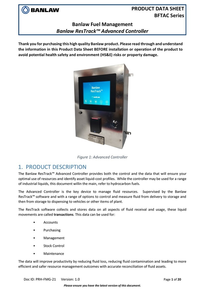
BANLAW BRT33WSMA Operational manual

PRODUCT DATA SHEET
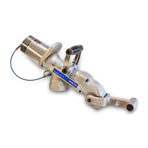
BANLAW SECUREFILL DRY BREAK AUTO ID WIRELESS SWIVEL
BRT33WSMA,BRT34WSMA
Doc ID: PRH-FMG-76 Version: 1.0 Page 1 of 14
Please ensure you have the latest version of this document.
Thank you for purchasing this high quality Banlaw product. Please read through and understand
the information in this Product Data Sheet (PDS) BEFORE installation or operation of the product
to avoid potential health, safety and environment (HS&E) risks or property damage.
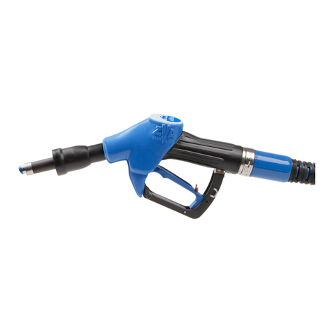
figure 1 Banlaw SecureFill Dry Break Auto ID Wireless Swivel (BRT34WSA)
1PRODUCT DESCRIPTION
The Banlaw SecureFill Dry-Break Auto ID Wireless Swivel, hereafter referred to as the Wireless Swivel,
represents an innovative evolution of the Banlaw Dry Break “Auto ID” system. The use of wireless
technology provides the same fuel security as the wired FuelTrack Dry-Break Auto ID system with up
to twice the range of the wired Auto ID system.
The Wireless Swivel acts as a conventional swivel and an interface to the ID tag in the attached receiver. The
tag ID is communicated from the Wireless Swivel to the ResTrack System via the Wireless Controller HID. The
use of contact-based identification greatly improves reliability while maintaining security. The Wireless
Swivel is only compatible with Banlaw Auto ID Nozzles, Receivers, and the ResTrack Resource Management
System.
The Wireless Swivel is screwed into the nozzle and provides a rotating mechanical connection between the
hose and the nozzle. The Wireless Swivel detects the ID tag in the receiver and communicates the unique Tag
ID to the ResTrack System via the wireless gateway. The Contact-based identification between the swivel and
the Auto ID receiver greatly improves reliability and security and is fully compatible with previous generation
Banlaw Auto ID nozzles.
The Electronics module (BRTWSMA) on the swivel assembly can be replaced when necessary. The Wireless
Swivel is designed for Ultra-low power consumption for extended battery life.
Two LED’s (green & red) on the Wireless Swivel communicate system status to the operator.
The Wireless swivel is compliant with design requirements for Explosive Atmospheres (Hazardous Zones -
ATEX).

BANLAW PRODUCT DATA SHEET PRODUCT NAME
Doc ID: PRH-FMG-76 Version: 1.0 Page 2 of 14
Please ensure you have the latest version of this document.
1.1 Operation
The Wireless Swivel operates continuously and when not in use enters a sleep mode to conserve battery
power. An internal accelerometer senses movement and wakes the swivel. The status of the Wireless Swivel
can be determined from the two status LEDs visible through the LED status window, see Figure 2 below.
Figure 2 Location of LED status window and magnet reset zone.
The table below shows status LEDs indication
Red LED
Green LED
Status
Fast red and green flashing pattern
After the control board boots up, the controller searches
for wireless firmware update for approximatly 5 seconds.
If the controller detects a firmware update, wireless
firmware download starts and both red and green LEDs
flash. When firmware download is comple the controller is
reset to load the new firmware.
Flashing rapidly for 1 sec
Application firmware has started.
Continuously flashing at
1.5 / sec
Wireless swivel control board is waiting for iButton
contact.
Flashing quickly twice
iButton has disconnected. The nozzle is disconneted from
receiver.
Continuously flashing 1.5
times / sec
Wireless swivel control board is sending iButton data to a
gateway device. The nozzle is connected to a receiver
Flashing quickly 2 times
iButton has been connected.
OFF
OFF
Wireless swivel control board is sleeping (shake the
Wireless Swivel to wake up)
Reseting the Wireless Swivel. The Wireless Swivel is a potted assembly and has no mechanical reset switch.
However the control board has a magnetic reset switch that can be envoked if a reset is required. To reset
the control board place a magnet over the reset zone (shown in Figure 2). Reset can be verified by viewing
the status LEDs.
Magnet
Reset
Zone
LED
Status
Window

BANLAW PRODUCT DATA SHEET PRODUCT NAME
Doc ID: PRH-FMG-76 Version: 1.0 Page 3 of 14
Please ensure you have the latest version of this document.
2IMPORTANT RESTRICTIONS ON THE USE OF THIS PRODUCT
The safe installation and operation of this Banlaw Wireless Swivel rely on the
completion of an assessment of the systems suitability for the intended application.
This assessment is best achieved through the cooperation of the end-user and Banlaw.
Once the assessment is completed and deems the system to be suitable, the end-user
must ensure effective change management should any requirement on which the
assessment was based on changes.
This Banlaw document does not contain an exhaustive list of Regulatory requirements
related to the use of the system in all international countries and regions. It is the
responsibility of the end user to ascertain the relevant Regulatory and Statutory
requirements that apply in the country or region in which the system is to be used.
This document is not meant to substitute or override any such Regulatory and
Statutory requirements, nor is this document meant to inform the end user of all such
requirements that may apply to the use of this Banlaw system.
The information within this Banlaw document was correct at the time of writing. End-
users are responsible for obtaining and assessing any labels, documents or other
media for a third-party product supplied by Banlaw to confirm the required approvals,
certifications and specifications of the product are appropriate for the intended
application.
Regional Regulations/Codes/Standards/Guidelines etc. may cover the use of certain
features of hardware on mining plant.
•Banlaw Pty Ltd proprietary product is approved under FCC and CE governances.
Additional and/or different product certification/approval requirements may
apply under alternative governances.
•Certification and/or Approval governances will apply to the use of wireless
communication device within a hazardous area (i.e. explosive atmosphere). End-
users are responsible for only the use of suitably certified products within such
areas.

BANLAW PRODUCT DATA SHEET PRODUCT NAME
Doc ID: PRH-FMG-76 Version: 1.0 Page 4 of 14
Please ensure you have the latest version of this document.
3LOW FREQUENCY RECEIVER AND TRANSMITTER REGULATORY INFORMATION
US - FCC Warning Statement
FCC ID : 2A28Y-BRTWSMA
This device complies with Part 15 of the FCC Rules. Operation is subject to the following two conditions: (1) This device
may not cause harmful interference, and (2) this device must accept any interference received, including interference
that may cause undesired operation.
FCC Caution: Any changes or modifications not expressly approved by the party responsible for compliance could void
the user's authority to operate this equipment.
This equipment has been tested and found to comply with the limits for a Class B digital device, pursuant to Part 15 of
the FCC Rules. These limits are designed to provide reasonable protection against harmful interference in a residential
installation. This equipment generates, uses and can radiate radio frequency energy and, if not installed and used in
accordance with the instructions, may cause harmful interference to radio communications. However, there is no
guarantee that interference will not occur in a particular installation. If this equipment does cause harmful interference
to radio or television reception, which can be determined by turning the equipment off and on, the user is encouraged
to try to correct the interference by one or more of the following measures:
• Reorient or relocate the receiving antenna.
• Increase the separation between the equipment and receiver.
• Connect the equipment into an outlet on a circuit different from that to which the receiver is connected.
• Consult the dealer or an experienced radio/TV technician for help.
This device and its antenna(s) must not be co-located or operating in conjunction with any other antenna or transmitter.
FCC Radiation Exposure Statement:
This equipment complies with FCC radiation exposure limits set forth for an uncontrolled environment. This equipment
should be installed and operated with minimum distance 20cm between the radiator & your body.
Canada- ISED Warning statement
IC : 28132-BRTWSMA
This device contains licence-exempt transmitter(s)/receiver(s) that comply with Innovation, Science and Economic
Development Canada’s licence-exempt RSS(s). Operation is subject to the following two conditions:
1. This device may not cause interference.
2. This device must accept any interference, including interference that may cause undesired operation of the device.
L’émetteur/récepteur exempt de licence contenu dans le présent appareil est conforme aux CNR d’Innovation,
Sciences et Développement économique Canada applicables aux appareils radio exempts de licence. L’exploitation est
autorisée aux deux conditions suivantes :
1. L’appareil ne doit pas produire de brouillage;
2. L’appareil doit accepter tout brouillage radioélectrique subi, même si le brouillage est susceptible d’en
compromettre le fonctionne ment.
IC Radiation Exposure Statement:
This equipment complies with IC RSS-102 radiation exposure limits set forth for an uncontrolled environment. This
equipment should be installed and operated with minimum distance 20cm between the radiator & your body.
Cet équipement est conforme aux limites d’exposition aux rayonnements IC établies pour un environnement non
contrôlé. Cet équipement doit être installé et utilisé avec un minimum de 20cm de distance entre la source de
rayonnement et votre corps.
The transmitter module may not be co-located with any other transmitter or antenna.
Le module émetteur peut ne pas être complanté avec un autre émetteur ou antenne.
CAN ICES-003(B)/NMB-003(B)
BANLAW PRODUCT DATA SHEET PRODUCT NAME
Doc ID: PRH-FMG-76 Version: 1.0 Page 5 of 14
Please ensure you have the latest version of this document.
Australia and New Zealand Conformance Statement
This product conforms to Australia and New Zealand Radio Requirements.
4SPECIFICATIONS
Product Name
SecureFill Dry Break Auto ID Wireless Swivel
Display
2 status LEDs
Weight
1.25 Kg
RF Frequency
433 MHZ
Internal Sensors
Accelerometer
Magneto resistive sensor (magnetic reset switch)
Operating Range
25 meters (direct line of sight)
Operating Voltage
3.6 VDC x 2.6Ah Lithium-Thionyl Chloride battery Compliant
with IEC60086-4, IEC60079-11 and UL1642 certified
Battery Life
~ 2-years battery life @ 120 minutes per day operation @20°C
Operating Temperature
-25°C <T°C<85°C
Storage Temperature
-25°C <T°C<85°C
IP Rating
IP66
3.1 Dimensions
Figure 3: Dimensions of SecureFill Dry Break Auto ID Wireless Swivel (mm)
Part No
Dimension “A”
BRT33WSA
1-1/2” NPT(F)
BRT34WSA
2” NPT(F)

BANLAW PRODUCT DATA SHEET PRODUCT NAME
Doc ID: PRH-FMG-76 Version: 1.0 Page 6 of 14
Please ensure you have the latest version of this document.
5CONFIGURATION
The Wireless Swivel requires no configuration prior to installation.
5.1 Wireless Swivel - Advanced Controller Registration
Step
Figure
Attach the Wireless Swivel to a FuelTrack
nozzle. The LED should blink red. (This
indicates the swivel is powered)
Attach the nozzle to the receiver (see Blue
arrow). The LED will blink green.
If the LED is still red actuate the nozzle
handle. (This connects the swivel to the
nozzle Auto ID button).
Note: If any problems are encountered refer
to troubleshooting guide.
Note: Do not connect to a receiver if there is
potential for a fuel spill.
Click the “Functions” button on the
Advanced controller
Select the “SecureFill Nozzle Reader” option.

BANLAW PRODUCT DATA SHEET PRODUCT NAME
Doc ID: PRH-FMG-76 Version: 1.0 Page 7 of 14
Please ensure you have the latest version of this document.
Step
Figure
Enter a Supervisor (Level 2) Pin number.
Select “Done” then “Next”.
Select the nozzle that the Wireless Swivel is
to control. In this case it will be nozzle 1.
Select “Next”
The Wireless Swivel’s serial number is shown
on the list. Select that serial number and click
next to complete the process.
Note: If the required number is not displayed
refer to the troubleshooting guide.
Note: The serial number is marked on the
Wireless Swivel.
The Wireless Swivel is now paired to the
nozzle. Auto ID receivers will now be read
into the controller and begin a transaction.
5.2 Wireless Swivel - Xpress Controller Registration
Step
Figure
Attach the Wireless Swivel to a FuelTrack
nozzle. The LED should blink red. (This
indicates the swivel is powered)

BANLAW PRODUCT DATA SHEET PRODUCT NAME
Doc ID: PRH-FMG-76 Version: 1.0 Page 8 of 14
Please ensure you have the latest version of this document.
Step
Figure
Attach the nozzle to the receiver (see Blue
arrow). The LED will blink green.
If the LED is still red actuate the nozzle
handle. (This connects the swivel to the
nozzle Auto ID button).
Note: If any problems are encountered refer
to troubleshooting guide.
Note: Do not connect to a receiver if there
is potential for a fuel spill.
Press “FUNCTIONS” button on touch glass
and select #9 “User Selection”
Select “Wireless Swivel”

BANLAW PRODUCT DATA SHEET PRODUCT NAME
Doc ID: PRH-FMG-76 Version: 1.0 Page 9 of 14
Please ensure you have the latest version of this document.
Step
Figure
Xpress starts searching for 3 seconds
Wireless swivel, battery %, and tag are
displayed.
Note: If the required number is not
displayed refer to the troubleshooting
guide.

BANLAW PRODUCT DATA SHEET PRODUCT NAME
Doc ID: PRH-FMG-76 Version: 1.0 Page 10 of 14
Please ensure you have the latest version of this document.
Step
Figure
Verify that swivel ID matches the Serial
Number on the Swivel housing and the Tag
ID matches the ID on the receiver.
If the swivel is not discovered, Wireless
Swivel Management screen will look like on
the screenshot.

BANLAW PRODUCT DATA SHEET PRODUCT NAME
Doc ID: PRH-FMG-76 Version: 1.0 Page 11 of 14
Please ensure you have the latest version of this document.
Step
Figure
•To add the discovered Wireless
Swivel, type in nozzle number to be
assigned and press “<“ button.
•To remove the assigned Wireless
Swivel from the nozzle, type in
nozzle number and press “>” button.
•To save changed settings, press
“DONE” button
•To skip saving changed settings,
press “CANCEL” button.
After saving the changes, Xpress will
automatically reboot and the Wireless
Swivel will be paired to the nozzle. System is
ready to resume normal operation.
6INSTALLATION GUIDE
Prior to commencing the installation conduct a Health Safety and Environment (HS&E,
WHS) risk assessment (e.g. SWMS or JHA). For a typical installation, particular attention
is drawn to the following areas:
•Isolation and bleeding of residual fuel pressure.
•Appropriate personal protective equipment (PPE).
•Use of appropriate tools and equipment.
•Use of trained, qualified and competent personnel.
•Barricade the area (if required) to restrict unauthorised personnel and vehicle
access.
•Place Personal Locks, Tags etc. on equipment required to be positively isolated.
•The presence of a spill kit designed to manage fuel spills.
•The presence and good working order of fire suppression devices such as fire
extinguishers.
•If performing any work within a zone/area classified as hazardous (i.e. explosive
atmosphere), strictly adhere to all necessary precautions etc. applicable to work in
such areas. Such precautions are likely to include the use of specialist (certified)
equipment.
•Assessment of and adherence to all relevant Regulatory and Statutory guidelines.
•Assessment of and adherence to all relevant product OEM installation guidelines.
This section describes the installation procedure of Wireless Swivel:
•The Wireless swivel will be shipped with a magnet mounted on the magnetic reset button, to save
the battery prior to usage. Please remove the magnet before installing the Wireless swivel
•Screw the hose tail into the Wireless Swivel.
•Screw the Nozzle onto the Wireless Swivel.
•Apply Loctite 567 thread sealant to the threaded hose-swivel-nozzle joints. Make sure all threads are
clean and dry before applying the Loctite.

BANLAW PRODUCT DATA SHEET PRODUCT NAME
Doc ID: PRH-FMG-76 Version: 1.0 Page 12 of 14
Please ensure you have the latest version of this document.
On completion of the installation the Wireless Swivel must be registered with the Depot, see section 4.
Loctite products should be applied sparingly to the swivel threads for the Banlaw
FuelTrackTM system installation. Excessive use of Loctite products between the
threads may cause an electrical resistance which may provide a significant enough
voltage drop to cause the FuelTrackTM system to not detect a positive connection.
In case the conditions do not allow the thread to be clean and dry, thread tape can
be used instead. Excessive use of thread tape may cause an electrical resistance
which may provide a significant enough voltage drop to cause the FuelTrackTM
system to not detect a positive connection.
Figure 6: Probe extending from the Wireless Swivel.
Figure 7: Banlaw FuelTrack nozzle inlet, showing internal data probe contact.
Due to the numerous requirements that apply to a Banlaw product, the client shall liaise
with Banlaw prior to the use of the product within an application that is deemed to be
“uncommon”. The majority of Banlaw clients should already be familiar with Banlaw
products, and the applications for which each product/system are suited.
Failing to properly and identify, investigate, assess and conform with all requirements
for a Banlaw product application may pose serious risks, hazards and consequences.
“IF IN DOUBT, ASK!”

BANLAW PRODUCT DATA SHEET PRODUCT NAME
Doc ID: PRH-FMG-76 Version: 1.0 Page 13 of 14
Please ensure you have the latest version of this document.
7MAINTENANCE
It is typically a legal responsibility of the person(s) who have identified the hazard to
isolate the system whose use is likely to result in an unacceptable risk to health, safety
and environment. Complete the applicable procedure for the proper and positive
isolation of the system and inform worksite management immediately.
The scope of this section is restricted to recommended service and maintenance
requirements for the Wireless Swivel. It is the responsibility of the end-user to identify
and adequately conduct any necessary service and maintenance for other equipment
and items within the fluid transfer system.
The maintenance options for the swivel are:
7.1 Mechanical failure
The Banlaw Steel Swivel is a non-serviceable item, and no attempt should be made to repair the Swivel.
Should fuel leakage be detected from between the Swivel Body and Swivel Inner part, it is likely that the
other components have worn sufficiently to cause the seal failure. The defective Swivel should be replaced
and recycled immediately.
The mechanical replacement product in case of a failure is BRT34WS01 (2” version) and BRT33WS01 (1.5”
version). Demount the Module described in 7.2 and replace the mechanical body.
7.2 Electronics failure
The electronics assembly can be replaced if it fails. Use the following procedure:
•Obtain a replacement Wireless Swivel Module (BRTWSMA)
•Remove 8 screws see, Figure 6, below,
•Separate module halves,
•Remove module,
•Attach new module,
•Replace 8 screws,
•Verify that the red LED flashes when the swivel is moved,
•Connect the swivel to a nozzle as per section 5. Configuration of this document and register the swivel
following the steps for either the Advanced Controller or the Xpress Controller
Figure 8 Exploded view of the Wireless Swivel

BANLAW PRODUCT DATA SHEET PRODUCT NAME
Doc ID: PRH-FMG-76 Version: 1.0 Page 14 of 14
Please ensure you have the latest version of this document.
Batteries used in this system contain lithium-thionyl chloride. Please follow appropriate
battery disposal or recycling practices for used batteries of this type.
8TROUBLESHOOTING
If the Wireless Swivel stops transmitting vehicle’s information, please follow the below troubleshooting
guide.
ISSUE
POSSIBLE SOLUTION(S)
No LED activity
1. Wireless Swivel is asleep, move assembly and observe red LED
flashes at 1.5 times / second. If there is still no LED activity,
then proceed to step 2.
No LED activity after
movement
2. If the Wireless Swivel fails to activate after movement, reset
the Wireless Swivel using a magnet.
3. Place a magnet on the magnet reset zone (see figure 2) and
remove rapidly. Observe red and green LEDs flash rapidly for a
second. Then no activity for approx. 6 seconds then red LED
flashes at 1.5 times / second.
No LED activity after reset
4. If there is still no LED activity either the battery is discharged,
or the electronics has failed. Replace the electronic module.
Advanced or Xpress
controller fails to identify
the Wireless Swivel
5. Observe Wireless Swivel LED activity and troubleshoot as per
steps 1 to 4. If the swivel is still not recognised, replace the
swivel.
6. If the fault persists, troubleshoot the Advanced or Xpress
Controller as per Controller Installation and Maintenance
Procedure.
9OPTIONAL ACCESSORIES & SPARE PARTS
Item/Description
Banlaw Part Number
Electronics module
BRTWSMA
Mechanical body 1.5”
BRT33WS01
Mechanical body 2”
BRT34WS01
Banlaw does not recommend nor endorse the use of non-genuine replacement
(spare) parts. The use of spare parts not endorsed by the product OEM is likely to
void a product warranty and may jeopardise the safety, performance/function,
reliability, and regulatory certifications/approvals of the product.
Banlaw makes no guarantees and assumes no liability for circumstances arising out
of the accuracy and completeness of third-party product specifications included
within this document. The verification, validation, and publishing of specifications
for any product remain the responsibility of the product OEM.
END OF DOCUMENT
Website –www.banlaw.com
This manual suits for next models
1
Table of contents
Other BANLAW Petrol Station Equipment manuals