GILBARCO VEEDER-ROOT Encore 700 S Guide

Encore®700 S
Start-up and Service Manual
MDE-4902E

Computer Programs and Documentation
All Gilbarco Inc. and/or Veeder-Root Company computer programs (including software on diskettes and within memory chips) and documentation are copyrighted by, and shall
remain the property of, Gilbarco Inc. and/or Veeder-Root Company. Such computer programs and documents may also contain trade secret information. The duplication, disclosure,
modification, or unauthorized use of computer programs or documentation is strictly prohibited, unless otherwise licensed by Gilbarco Inc. and/or Veeder-Root Company.
Federal Communications Commission (FCC) Warning
This equipment has been tested and found to comply with the limits for a ClassA digital device pursuant to Part 15 of the FCC Rules. These limits are designed to provide
reasonable protection against harmful interference when the equipment is operated in a commercial environment. This equipment generates, uses, and can radiate radio frequency
energy, and if not installed and used in accordance with the instruction manual, may cause harmful interference to radio communications. Operation of this equipment in a
residential area is likely to cause harmful interference in which case the user will be required to correct the interference at his own expense. Changes or modifications not expressly
approved by the manufacturer could void the user’s authority to operate this equipment.
Approvals
Trademarks
Gilbarco is an ISO 9001:2008 registered company.
Underwriters Laboratories (UL):
ULFile# Products listed with UL
MH1941 All Gilbarco pumps and dispensers that bear
the UL listing mark.
MH8467 Transac System 1000 and PAM 1000
E105106 Dell DHM Minitower
E165027 G-SITE and Passport Systems
National Conference of Weights and Measures (NCWM) - Certificate of Conformance (CoC):
Gilbarco pumps and dispensers are evaluated by NCWM under the National Type Evaluation Program (NTEP). NCWM has issued the following CoC:
CoC# Product Model # CoC# Product Model #
02-019 Encore Nxx 02-036 Legacy Jxxx
02-020 Eclipse Exx
02-037
G-SITE Printer (Epson) PA0307
02-025 Meter - C Series PA024NC10 G-SITE Distribution Box PA0306
Meter - C Series PA024TC10 G-SITE Keyboard PA0304
02-029 CRIND — G-SITE Mini Tower PA0301
02-030
TS-1000 Console — G-SITE Monitor PA0303
TS-1000 Controller PA0241 G-SITE Printer (Citizen) PA0308
Distribution Box PA0242 02-038 C+ Meter T19976
Meter - EC Series PA024EC10 02-039 Passport PA0324
VaporVac Kits CV 02-040 Ecometer T20453
05-001 Titan KXXY Series
California Air Resources Board (CARB):
Executive Order # Product
G-70-52-AM Balance Vapor Recovery
G-70-150-AE VaporVac
Registered trademarks
CRIND®Making Things Better®VaporVac®
Dimension®Series MPD®
e-CRIND®Passport®
Eclipse®Performer®
Encore®The Advantage® Series
G-SITE®Transac®
Gilbarco®Transac®System 1000
InfoScreen®Trimline®
Legacy®TRIND®
Additional US and foreign trademarks pending.
Other brand or product names shown may be trademarks or registered trademarks of their respective holders.
This document is subject to change without notice.
http://www.gilbarco.com
2018 Gilbarco Inc. All Rights Reserved
Service mark
GOLDSM
Non-registered trademarks
Applause™Media System G-SITE®Link™PAM™5000 Titan™
CIM™G-SITE®Lite™SMART Connect™Ultra-Hi™
C-PAM™Highline™SMART CRIND™ValueLine™
Ecometer™Horizon™SMART Meter™
ECR™Insite360™SmartPad™
EMC™MultiLine™Super-Hi™
FlexPay™Optimum™Series Surge Management System™
G-CAT™PAM™Tank Monitor™
Gilbert™PAM™1000 TCR™

MDE-4902E Encore® 700 S Start-up and Service Manual · February 2018 Page i
Table of Contents
Table of Contents
1 – Introduction 1-1
Purpose. . . . . . . . . . . . . . . . . . . . . . . . . . . . . . . . . . . . . . . . . . . . . . . . . . . . . . . . . . . . . . . . . . . . . . . . . . . . . . . . 1-1
Encore 700 S CRIND System . . . . . . . . . . . . . . . . . . . . . . . . . . . . . . . . . . . . . . . . . . . . . . . . . . . . . . . . . . . . . . . 1-1
Related Documents. . . . . . . . . . . . . . . . . . . . . . . . . . . . . . . . . . . . . . . . . . . . . . . . . . . . . . . . . . . . . . . . . . . . . . . 1-2
Recommended Spare Parts . . . . . . . . . . . . . . . . . . . . . . . . . . . . . . . . . . . . . . . . . . . . . . . . . . . . . . . . . . . . . . . . 1-2
Abbreviations and Acronyms. . . . . . . . . . . . . . . . . . . . . . . . . . . . . . . . . . . . . . . . . . . . . . . . . . . . . . . . . . . . . . . . 1-2
Common Terms. . . . . . . . . . . . . . . . . . . . . . . . . . . . . . . . . . . . . . . . . . . . . . . . . . . . . . . . . . . . . . . . . . . . . . . . . . 1-4
2 – Important Safety Information 2-1
3 – Start-up 3-1
Configuring CRIND . . . . . . . . . . . . . . . . . . . . . . . . . . . . . . . . . . . . . . . . . . . . . . . . . . . . . . . . . . . . . . . . . . . . . . . 3-1
CRIND IDs. . . . . . . . . . . . . . . . . . . . . . . . . . . . . . . . . . . . . . . . . . . . . . . . . . . . . . . . . . . . . . . . . . . . . . . . . . . . . . 3-2
CRIND Mode. . . . . . . . . . . . . . . . . . . . . . . . . . . . . . . . . . . . . . . . . . . . . . . . . . . . . . . . . . . . . . . . . . . . . . . . . . . . 3-3
Configuring Network for Sites with DCM2 or Earlier (without SSoM) . . . . . . . . . . . . . . . . . . . . . . . . . . . . . . . . . 3-4
Configuring Network with DCM2.1 (with SSoM) and Later Hardware. . . . . . . . . . . . . . . . . . . . . . . . . . . . . . . . . 3-6
Resetting Default IPs . . . . . . . . . . . . . . . . . . . . . . . . . . . . . . . . . . . . . . . . . . . . . . . 3-8
Setting IP Addresses . . . . . . . . . . . . . . . . . . . . . . . . . . . . . . . . . . . . . . . . . . . . . . . 3-9
Applying Network Settings . . . . . . . . . . . . . . . . . . . . . . . . . . . . . . . . . . . . . . . . . . 3-12
Viewing Network Settings . . . . . . . . . . . . . . . . . . . . . . . . . . . . . . . . . . . . . . . . . . 3-13
Hiding Network Settings. . . . . . . . . . . . . . . . . . . . . . . . . . . . . . . . . . . . . . . . . . . . 3-13
Adjusting Audio Volume Level. . . . . . . . . . . . . . . . . . . . . . . . . . . . . . . . . . . . . . . . . . . . . . . . . . . . . . . . . . . . . . 3-15
Setting Default Personality . . . . . . . . . . . . . . . . . . . . . . . . . . . . . . . . . . . . . . . . . . . . . . . . . . . . . . . . . . . . . . . . 3-16
Setting Date and Time. . . . . . . . . . . . . . . . . . . . . . . . . . . . . . . . . . . . . . . . . . . . . . . . . . . . . . . . . . . . . . . . . . . . 3-17
4 – Service 4-1
Encore 700 S Block Diagrams. . . . . . . . . . . . . . . . . . . . . . . . . . . . . . . . . . . . . . . . . . . . . . . . . . . . . . . . . . . . . . . 4-1
Diagnostics and Visual Checks (After Installation) . . . . . . . . . . . . . . . . . . . . . . . . . . . . . . . . . . . . . . . . . . . . . . . 4-6
Encore 700 S PCBs. . . . . . . . . . . . . . . . . . . . . . . . . . . . . . . . . . . . . . . . . . . . . . . . . . . . . . . . . . . . . . . . . . . . . . . 4-7
LEDs . . . . . . . . . . . . . . . . . . . . . . . . . . . . . . . . . . . . . . . . . . . . . . . . . . . . . . . . . . . 4-7
FlexPay Control Board [FCB (M11930K001)] . . . . . . . . . . . . . . . . . . . . . . . . . . . . . . . . . . . . . . . . . . . . . . . . . . 4-16
DCM2.2 . . . . . . . . . . . . . . . . . . . . . . . . . . . . . . . . . . . . . . . . . . . . . . . . . . . . . . . . . . . . . . . . . . . . . . . . . . . . . . . 4-19
DCM2.2 (M15737A001) Highlights . . . . . . . . . . . . . . . . . . . . . . . . . . . . . . . . . . . 4-19
DCM2.2 LED Functions . . . . . . . . . . . . . . . . . . . . . . . . . . . . . . . . . . . . . . . . . . . . 4-19
DCM2.2 LED Indicators . . . . . . . . . . . . . . . . . . . . . . . . . . . . . . . . . . . . . . . . . . . . 4-20
DCM2.2 Connectors. . . . . . . . . . . . . . . . . . . . . . . . . . . . . . . . . . . . . . . . . . . . . . . 4-20
DCM2.2 Jumpers . . . . . . . . . . . . . . . . . . . . . . . . . . . . . . . . . . . . . . . . . . . . . . . . . 4-21
5 – Activating Encore 700 S CRIND 5-1
Overview . . . . . . . . . . . . . . . . . . . . . . . . . . . . . . . . . . . . . . . . . . . . . . . . . . . . . . . . . . . . . . . . . . . . . . . . . . . . . . . 5-1
Configuring/Activating Encore 700 S CRIND . . . . . . . . . . . . . . . . . . . . . . . . . . . . . . . . . . . . . . . . . . . . . . . . . . . 5-2
Appendix A: Diagnostic Screens A-1
Yellow Screen . . . . . . . . . . . . . . . . . . . . . . . . . . . . . . . . . . . . . . . . . . . . . . . . . . . . . . . . . . . . . . . . . . . . . . . . . . . A-1
Red Screen . . . . . . . . . . . . . . . . . . . . . . . . . . . . . . . . . . . . . . . . . . . . . . . . . . . . . . . . . . . . . . . . . . . . . . . . . . . . . A-1
Blue Screen. . . . . . . . . . . . . . . . . . . . . . . . . . . . . . . . . . . . . . . . . . . . . . . . . . . . . . . . . . . . . . . . . . . . . . . . . . . . . A-2
Green Screen . . . . . . . . . . . . . . . . . . . . . . . . . . . . . . . . . . . . . . . . . . . . . . . . . . . . . . . . . . . . . . . . . . . . . . . . . . . A-2

Table of Contents
Page ii MDE-4902E Encore® 700 S Start-up and Service Manual · February 2018
Appendix B: Troubleshooting Encore 700 S CRIND Communication Issues B-1
CRIND Communication Problems . . . . . . . . . . . . . . . . . . . . . . . . . . . . . . . . . . . . . . . . . . . . . . . . . . . . . . . . . . . B-1
Appendix C: Encore 700 S Start-up Checklist C-1
Appendix D: Encore 700 S Recommended Spare Parts D-1
Appendix E: FlexPay II CRIND Retrofit TRIND Settings D-1
Index Index-1

MDE-4902E Encore® 700 S Start-up and Service Manual · February 2018 Page 1-1
Purpose Introduction
1 – Introduction
Purpose
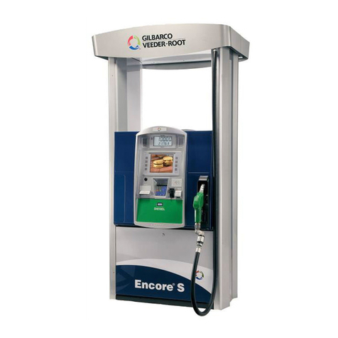
This manual provides start-up and service information for the Encore®700 S CRIND®system.
This manual also applies to TheAdvantage® Series, Encore 300/500/500 S with E-CIM™
systems that may have been upgraded with FlexPay™II CRIND retrofit kits and Insite360™
Encore (Remote Management) kits using the DCM2.1/DCM2.2. For more information, refer
to MDE-5314 Insite360™Encore Remote Management Installation, Start-up, and Service
Manual.
Figure 1-1: Encore 700 S CRIND System
Encore 700 S CRIND System
The Encore 700 S CRIND system is certified as Payment Card Industry-Unattended Payment
Terminal (PCI-UPT) 1.X compliant and is designed to provide enhanced security to the
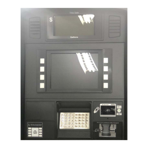
fueling environment. The CRIND device uses a 5.7-inch color or 10.4-inch color display,
FlexPay Encrypting PIN Pad (EPP) 2.1, and Secure Card Reader 2 (SCR 2).
The following options are available in the CRIND system:
•TRIND
®
• Barcode Scanner
• Cash Acceptor
•TheApplause
™Media System with Audio/Video
• Insite360 Encore (Remote Management)

Introduction Related Documents
Page 1-2 MDE-4902E Encore® 700 S Start-up and Service Manual · February 2018
Related Documents
Document
Number Title GOLDSM Library
MDE-3802 Encore and Eclipse®Site Preparation Manual • Encore and Eclipse
• Encore and Eclipse Installers
• Footprints and Elevations
• Site Prep
MDE-3902 Call Button Kit K96636-01 for Encore Dispensers Encore and Eclipse
MDE-3985 Encore Installation Manual • Encore and Eclipse
• Encore and Eclipse Installers
• Footprints and Elevations
MDE-4185 CRIND Encore 700 S Electronics CRIND BIOS Configuration
Interface Manual • CRIND and TRIND
• Encore and Eclipse
MDE-5062 FlexPay Maintenance Tool for FlexPay/SPOT CRIND System • CRIND and TRIND
• FlexPay IV EMV®
MDE-5314 Insite360 Encore Remote Management Installation, Start-up,
and Service Manual • FlexPay EPP and SCR
• FlexPay IV
Installation and site preparation for the Encore 700 S is identical to that of the Encore
500 S. For installation and site preparation details, refer to MDE-3985 Encore
Installation Manual, MDE- 3902 Call Button Kit K96636-01 for Encore Dispensers, and
MDE-3802 Encore and Eclipse Site Preparation Manual.
IMPORTANT INFORMATION
Recommended Spare Parts
For Encore 700 S recommended spare parts list, refer to “Appendix D: Encore 700 S
Recommended Spare Parts” on page D-1.
Abbreviations and Acronyms
Term Description
ACI Application Centric Infrastructure
ADA Americans with Disabilities Act
BIOS Basic Input/Output System
CPE Customer Premise Equipment
CRIND Card Reader in Dispenser
DES Data Encryption Standard
DSS Data Security Standard
E-CIM Enhanced Customer Interface Module
ECR™Encrypted Card Reader
EDH Enhanced Dispenser Hub
EMV Europay®, MasterCard®, and Visa®
EPP Encrypting PIN Pad

MDE-4902E Encore® 700 S Start-up and Service Manual · February 2018 Page 1-3
Abbreviations and Acronyms Introduction
FCB FlexPay Control Board
GOLD Gilbarco®Online Documentation
HIP Hub Interface PCB
IP Internet Protocol
LED Light Emitting Diode
LON Local Operating Network
LRE Long Reach Ethernet®
MOC Major Oil Company
MSDS Material Safety Data Sheet
OMAP Open Multimedia Applications Platform
PCA Printed Circuit Assembly
PCB Printed Circuit Board
PCI Payment Card Industry
PCN Pump Control Node
PIP Peripheral Interface PCB
POS Point of Sale
PIN Personal Identification Number
PPN Product Part Number
PPU Price per Unit
RKL Remote Key Loading
SCR Secure Card Reader
SPOT Secure Payment Outdoor Terminal
SRED Secure Reading and Exchange of Data
SSoM Secure System on Module
TAC Technical Assistance Center
TDES Triple Data Encryption Standard
TLS Transport Layer Security
TRIND Transmitter/Receiver in Dispenser
UPT Unattended Payment Terminal
Term Description

Introduction Common Terms
Page 1-4 MDE-4902E Encore® 700 S Start-up and Service Manual · February 2018
Common Terms
Term Description
CRIND CRIND may also be used to refer to the entire in-dispenser payment platform.
EPP A secure, tamper-responsive keypad device responsible for encrypting Personal Identification
Number (PIN) data for a debit account as entered by the customer. It is also capable of allowing
other non-PIN data to be entered.
HIP Designed for EMV Canada, reused in Encore 700 S product.
PCI An independent council originally formed by American Express®, Discover Financial Services, JCB,
MasterCard Worldwide, and Visa International, with the goal of managing the ongoing evolution of
the Payment Card Industry Data Security Standard (PCI-DSS).
POS Device in the typical retail-fueling environment that owns the interface to the card acquirer.
RS-232 Standard for serial binary data signals connecting between data terminal equipment and data circuit
terminating equipment.
TDES A more secure variant of the Data Encryption Standard (DES) encryption algorithm, uses a 112-bit
key, and uses a basic DES algorithm three times per 8-bit block.

MDE-4902E Encore® 700 S Start-up and Service Manual · February 2018 Page 2-1
Important Safety Information
2 – Important Safety Information
Notes: 1) Save this Important Safety Information section
in a readily accessible location.
2) Although DEF is non-flammable, Diesel is
flammable. Therefore, for DEF cabinets that are
attached to Diesel dispensers, follow all the
notes in this section that pertain to flammable
fuels.
This section introduces the hazards and safety precautions
associated with installing, inspecting, maintaining or servicing
this product. Before performing any task on this product, read
this safety information and the applicable sections in this
manual, where additional hazards and safety precautions for
your task will be found. Fire, explosion, electrical shock or
pressure release could occur and cause death or serious injury,
if these safe service procedures are not followed.
Preliminary Precautions
You are working in a potentially dangerous environment of
flammable fuels, vapors, and high voltage or pressures. Only
trained or authorized individuals knowledgeable in the related
procedures should install, inspect, maintain or service this
equipment.
Emergency Total Electrical Shut-Off
The first and most important information you must know is how
to stop all fuel flow to the pump/dispenser and island. Locate
the switch or circuit breakers that shut off all power to all fueling
equipment, dispensing devices, and Submerged Turbine
Pumps (STPs).
The EMERGENCY STOP, ALL STOP, and
PUMP STOP buttons at the cashier’s station
WILL NOT shut off electrical power to the
pump/dispenser. This means that even if you
activate these stops, fuel may continue to flow
uncontrolled.
You must use the TOTAL ELECTRICAL
SHUT-OFF in the case of an emergency and not
the console’s ALL STOP and PUMP STOP or
similar keys.
!
WARNING
!
Total Electrical Shut-Off Before Access
Any procedure that requires access to electrical components or
the electronics of the dispenser requires total electrical shut off
of that unit. Understand the function and location of this switch
or circuit breaker before inspecting, installing, maintaining, or
servicing Gilbarco equipment.
Evacuating, Barricading and Shutting Off
Any procedure that requires access to the pump/dispenser or
STPs requires the following actions:
• An evacuation of all unauthorized persons and vehicles from
the work area
• Use of safety tape, cones or barricades at the affected unit(s)
• A total electrical shut-off of the affected unit(s)
Read the Manual
Read, understand and follow this manual and any other labels
or related materials supplied with this equipment. If you do not
understand a procedure, call a Gilbarco Authorized Service
Contractor or call the Technical Assistance Center (TAC) at
1-800-743-7501. It is imperative to your safety and the safetyof
others to understand the procedures before beginning work.
Follow the Regulations
Applicable information is available in National Fire Protection
Association (NFPA) 30A; Code for Motor Fuel Dispensing
Facilities and Repair Garages, NFPA 70; National Electrical
Code (NEC), Occupational Safety and HealthAdministration
(OSHA) regulations and federal, state, and local codes. All
these regulations must be followed. Failure to install, inspect,
maintain or service this equipment in accordance with these
codes, regulations and standards may lead to legal citations
with penalties or affect the safe use and operation of the
equipment.
Replacement Parts
Use only genuine Gilbarco replacement parts and retrofit kits on
your pump/dispenser. Using parts other than genuine Gilbarco
replacement parts could create a safety hazard and violate
local regulations.
Safety Symbols and Warning Words
This section provides important information about warning
symbols and boxes.
Alert Symbol
This safety alert symbol is used in this manual and on
warning labels to alert you to a precaution which must be
followed to prevent potential personal safety hazards. Obey
safety directives that follow this symbol to avoid possible injury
or death.
Signal Words
These signal words used in this manual and on warning labels
tell you the seriousness of particular safety hazards. The
precautions below must be followed to prevent death, injury or
damage to the equipment:
DANGER:Alerts you to a hazard or unsafe practice
which will result in death or serious injury.
WARNING: Alerts you to a hazard or unsafe practice
that could result in death or serious injury.
CAUTION with Alert symbol: Designates a hazard or
unsafe practice which may result in minor injury.
CAUTION withoutAlert symbol: Designates a hazard or
unsafe practice which may result in property or
equipment damage.
Working With Fuels and Electrical Energy
Prevent Explosions and Fires
Fuels and their vapors will explode or burn, if ignited. Spilled or
leaking fuels cause vapors. Even filling customer tanks will
cause potentially dangerous vapors in the vicinity of the
dispenser or island.
DEF is non-flammable. Therefore, explosion and fire safety
warnings do not apply to DEF fluid lines.
!
!
!
Page 2-2 MDE-4902E Encore® 700 S Start-up and Service Manual · February 2018
Important Safety Information
No Open Fire
Open flames from matches, lighters, welding torches or
other sources can ignite fuels and their vapors.
No Sparks - No Smoking
Sparks from starting vehicles, starting or using power tools,
burning cigarettes, cigars or pipes can also ignite fuels and
their vapors. Static electricity, including an electrostatic charge
on your body, can cause a spark sufficient to ignite fuel vapors.
Every time you get out of a vehicle, touch the metal of your
vehicle, to discharge any electrostatic charge before you
approach the dispenser island.
Working Alone
It is highly recommended that someone who is capable of
rendering first aid be present during servicing. Familiarize
yourself with Cardiopulmonary Resuscitation (CPR) methods,if
you work with or around high voltages. This information is
available from the American Red Cross. Always advise the
station personnel about where you will be working, and caution
them not to activate power while you are working on the
equipment. Use the OSHA Lockout/Tagout procedures. If you
are not familiar with this requirement, refer to this information in
the service manual and OSHAdocumentation.
Working With Electricity Safely
Ensure that you use safe and established practices in working
with electrical devices. Poorly wired devices may cause a fire,
explosion or electrical shock. Ensure that grounding
connections are properly made. Take care that sealing devices
and compounds are in place. Ensure that you do not pinch
wires when replacing covers. Follow OSHA Lockout/Tagout
requirements. Station employees and service contractors need
to understand and comply with this program completely to
ensure safety while the equipment is down.
Hazardous Materials
Some materials present inside electronic enclosures may
present a health hazard if not handled correctly. Ensure that
you clean hands after handling equipment. Do not place any
equipment in the mouth.
The pump/dispenser contains a chemical known to the
State of California to cause cancer.
WARNING
!
The pump/dispenser contains a chemical known to the
State of California to cause birth defects or other
reproductive harm.
WARNING
!
In an Emergency
Inform Emergency Personnel
Compile the following information and inform emergency
personnel:
• Location of accident (for example, address, front/back of
building, and so on)
• Nature of accident (for example, possible heart attack, run
over by car, burns, and so on)
• Age of victim (for example, baby, teenager, middle-age,
elderly)
• Whether or not victim has received first aid (for example,
stopped bleeding by pressure, and so on)
• Whether or not a victim has vomited (for example, if
swallowed or inhaled something, and so on)
Gasoline/DEF ingested may cause
unconsciousness and burns to internal organs.
Do not induce vomiting. Keep airway open.
Oxygen may be needed at scene. Seek medical
advice immediately.
DEF generates ammonia gas at higher temperatures.
When opening enclosed panels, allow the unit to air out to
avoid breathing vapors.
If respiratory difficulties develop, move victim away from
source of exposure and into fresh air. If symptoms persist,
seek medical attention.
WARNING
!
WARNING
!
Gasoline inhaled may cause unconsciousness
and burns to lips, mouth and lungs.
Keep airway open.
Seek medical advice immediately.
WARNING
!
Gasoline/DEF spilled in eyes may cause burns to
eye tissue.
Irrigate eyes with water for approximately
15 minutes.
Seek medical advice immediately.
WARNING
!
Gasoline/DEF spilled on skin may cause burns.
Wash area thoroughly with clear water.
Seek medical advice immediately.
WARNING
!
DEF is mildly corrosive.Avoid contact with eyes, skin, and
clothing. Ensure that eyewash stations and safety
showers are close to the work location. Seek medical
advice/recommended treatment if DEF spills into eyes.
WARNING
!
IMPORTANT: Oxygen may be needed at scene if gasoline has
been ingested or inhaled. Seek medical advice immediately.
Lockout/Tagout
Lockout/Tagout covers servicing and maintenance of machines
and equipment in which the unexpected energization or start-
up of the machine(s) or equipment or release of stored energy
could cause injury to employees or personnel. Lockout/Tagout
applies to all mechanical, hydraulic, chemical, or other energy,
but does not cover electrical hazards. Subpart S of 29 CFR Part
1910 - Electrical Hazards, 29 CFR Part 1910.333 contains
specific Lockout/Tagout provision for electrical hazards.

MDE-4902E Encore® 700 S Start-up and Service Manual · February 2018 Page 2-3
Important Safety Information
Hazards and Actions
WARNING
Spilled fuels, accidents involving pumps/dispensers, or uncontrolled fuel flow create a
serious hazard.
Fire or explosion may result, causing serious injury or death.
Follow established emergency procedures.
DEF is non-flammable. However it can create a slip hazard. Clean up spills promptly.
Collision of a Vehicle with Unit Fire at Island Fuel Spill
The following actions are recommended regarding these hazards:
• Do not go near a fuel spill or allow anyone else in the area.
• Use station EMERGENCY CUTOFF immediately. Turn off all system circuit breakers to the island(s).
• Do not use console E-STOP, ALL STOP, and PUMP STOP to shut off power. These keys do not
remove AC power and do not always stop product flow.
• Take precautions to avoid igniting fuel. Do not allow starting of vehicles in the area. Do not allow
open flames, smoking or power tools in the area.
• Do not expose yourself to hazardous conditions such as fire, spilled fuel or exposed wiring.
• Call emergency numbers.
• Before visiting a site for a field trial, the technicians servicing or installing the Encore 700 S must
complete Gilbarco safety training.
• Safety vests must be worn at all times when at the site.
• Ensure compliance with safety rules and regulations set by the customer for performing service
procedures at their sites. Some customers may mandate the use of the following when
performing service:
- Hard Hats
- Safety Glasses
- Steel-toed ESD Shoes
- Gloves (when possible)
• When at the site, the technician must block out both sides of any dispenser that is being
serviced. The dispenser must be blocked off with either a car or set of safety cones.
• The technician must use the following equipment depending on the work being performed:
- Hearing Protection - if noise is over 85 db
- Job Safety Analysis (JSA) - for the work being performed
- Material Safety Data Sheet (MSDS), if required
- Injury reporting information
- First Aid kits and road side kits
IMPORTANT INFORMATION
!

Page 2-4 MDE-4902E Encore® 700 S Start-up and Service Manual · February 2018
Important Safety Information
This page is intentionally left blank.

MDE-4902E Encore® 700 S Start-up and Service Manual · February 2018 Page 3-1
Configuring CRIND Start-up
3 – Start-up
Configuring CRIND
The CRIND device on each side is programmed individually by inserting the CRIND
Diagnostic Card (Q12534-170) on each side (cannot be done from the same side). In CRIND
diagnostics, you must press Enter after each numeric key entry on the FlexPay EPP.
“Side 1” appears irrespective of the side being programmed.
Due to enhanced security of the FlexPay UPT, you must press Enter after each key entry
when using CRIND diagnostics.
IMPORTANT INFORMATION
Note: For more information on Encore 700 S Electronics CRIND Basic Input/Output System
(BIOS), refer to MDE-4185 CRIND Encore 700 S Electronics CRIND BIOS
Configuration Interface Manual.
To access CRIND diagnostic programming, proceed as follows:
1Insert and remove the CRIND diagnostic card.
Note: Card reader is sensitive to light and may not be able to read the card if the door is open.
Close the main doors to eliminate any outside light intrusion.
Figure 3-1: Swiping CRIND Diagnostic Card
CRIND Diagnostic Card (Q12534-170)

Start-up CRIND IDs
Page 3-2 MDE-4902E Encore® 700 S Start-up and Service Manual · February 2018
2From the Main Menu, press 1 >Enter. The CRIND Config menu is displayed.
Figure 3-2: CRIND Config Menu
CRIND Config
1. CRIND IDs
2. CRIND Mode
3. Generic BAUD Rate
4. Force BIOS Coldstart
5. Force App Coldstart
6. Set Date / Time
Cancel = Exit
Note: In most of the screens, pressing Cancel returns to the previous menu.
CRIND IDs
The CRIND IDs function allows you to program the CRIND ID for the side that is in front of
you.
1From the CRIND Config menu, press 1 >Enter. The CRIND IDs menu is displayed.
Figure 3-3: CRIND IDs Menu
CRIND IDs
1. CRIND ID Side 1
Cancel = Exit
Note: Each CRIND device is programmed separately by inserting the CRIND diagnostic card
on each side (cannot be done from the same side). The CRIND ID screen is called
“Side 1”, irrespective of the side being programmed.

MDE-4902E Encore® 700 S Start-up and Service Manual · February 2018 Page 3-3
CRIND Mode Start-up
2Press 1 >Enter. The CRIND ID Side 1 screen is displayed. (see Figure 3-4).
Note: Each CRIND device is programmed separately by inserting the CRIND diagnostic card
on each side (cannot be done from the same side). The CRIND ID screen is called
“Side 1” irrespective of the side being programmed.
Figure 3-4: CRIND ID Side 1
CRIND ID Side 1
CRIND ID 1
(Range: 1 - 32, 99 = disable)
Number Keys = Direct Entry
Clear = Erase Entry
Enter = Save Value and Exit
Cancel = Discard Change and Exit
Thecurrent CRINDcommunication
address for side 1.
3Press numeric keys to enter one-digit or two-digit CRIND ID. To enter a two-digit CRIND ID,
for example, 32, press 3> Enter and 2> Enter. Legal values for this field are 1-32 and 99.
Setting the value as 99 configures the side not to answer polls on the CRIND communication
loop. This is useful for field troubleshooting and diagnostic purposes.
4Press Enter to save the edited CRIND ID and exit. The CRIND IDs menu is displayed.
~ OR ~
Press Cancel to discard changes and exit. The program returns to the CRIND IDs menu.
CRIND Mode
To configure the CRIND Mode, proceed as follows:
1From the CRIND Config menu, press 2 >Enter. The CRIND Mode menu is displayed.
Figure 3-5: CRIND Mode
CRIND Mode
CRIND Mode MOC
1. MOC
2. Generic
Enter = Save Value and Exit
Cancel = Discard Change and Exit
Shows current setting. For new
installations or CRIND devices that have
undergone a purge or BIOS coldstart,
default will not be configured.

Start-up Configuring Network for Sites with DCM2 or Earlier (without SSoM)
Page 3-4 MDE-4902E Encore® 700 S Start-up and Service Manual · February 2018
2Press the following numeric keys followed by Enter to change the current CRIND Mode
setting:
•1causes the unit to operate in Major Oil Company (MOC) CRIND Mode.
•2causes the unit to operate in Generic CRIND Mode.
3Press Enter to save changes and exit. The CRIND Config menu is displayed.
~ OR ~
Press Cancel to discard changes and exit. The program returns to the CRIND Config menu.
Configuring Network for Sites with DCM2 or Earlier
(without SSoM)
CRIND side Internet Protocol (IP) addresses must not be changed from factory default
unless one of the following three conditions apply:
1) The site requires a non-standard IP scheme.
2) The site is configured for non-standard CRIND IDs.
3) Some third-party Point of Sale (POS) systems start with “0” instead of “1” as their
first CRIND ID.
For example, dispenser 1 is configured for CRIND IDs 1/4 instead of 1/2.
WARNING
WARNING
!
Note: The CRIND device on each side is independent of the CRIND device on the other side.
Each side must be programmed individually.
From the Main Menu, press 3 >Enter. The Network Config menu is displayed.
Figure 3-6: Network Config Menu
Network Config
1. Reset to Default IPs
2. Set IP Addresses
3. Apply Network Settings
4. View Network Settings
5. Hide Network Settings
Cancel = Exit

FlexPay II DCM1.0 and DCM2.0
Unit Default IP Address
Side A 10.5.55.71
Side B 10.5.55.72
Netmask 255.255.255.0
Default Gateway 10.5.55.1
SM Server 10.5.55.66
*IPAddressing 10.5.55.70 + CRIND ID
FlexPay IV DCM1.0 and DCM2.0
Unit Default IP Address
UPM A 10.5.55.71
UX 300 A 10.5.55.72
UPM B 10.5.55.73
UX 300 B 10.5.55.74
GSoM A 10.5.55.75
GSoM B 10.5.55.76
Default Gateway 10.5.55.1
Netmask 255.255.255.0
SM Server 10.5.55.66
*IPAddressing 10.5.55.70 + CRIND ID
MDE-4902E Encore® 700 S Start-up and Service Manual · February 2018 Page 3-5
Configuring Network for Sites with DCM2 or Earlier (without SSoM) Start-up
The IP addressing scheme for the units without Secure System on Module (SSoM) is
10.5.55.XXX.

Start-up Configuring Network with DCM2.1 (with SSoM) and Later Hardware
Page 3-6 MDE-4902E Encore® 700 S Start-up and Service Manual · February 2018
Configuring Network with DCM2.1 (with SSoM) and Later
Hardware
CRIND side IP addresses must not be changed from factory default unless one of the
following three conditions apply:
1) The site requires a non-standard IP scheme.
2) The site is configured for non-standard CRIND IDs.
3) Some third-party POS systems start with “0” instead of “1” as their first CRIND ID.
For example, dispenser 1 is configured for CRIND IDs 1/4 instead of 1/2.
WARNING
WARNING
!
Note: The CRIND device on each side is independent of the CRIND device on the other side.
Each side must be programmed individually.
From the Main Menu, press 3 >Enter. The Network Config menu is displayed.
Figure 3-7: Network Config Menu
Network Config
1. Reset to Default IPs
2. Set IP Addresses
3. Apply Network Settings
4. View Network Settings
5. Hide Network Settings
Cancel = Exit

FlexPay II DCM2.1
Unit Default IP Address
Side A 172.16.100.1
Side B 172.16.100.3
Netmask 255.255.255.0
Default Gateway 172.16.100.254
SM Server 10.5.55.66
FlexPay IV DCM2.1
Unit Default IP Address
UPM A 172.16.100.1
UX 300 A 172.16.100.2
UPM B 172.16.100.3
UX 300 B 172.16.100.4
GSoM A 172.16.100.5
GSoM B 172.16.100.6
Default Gateway 172.16.100.254
Netmask 255.255.255.0
SM Server 10.5.55.66
MDE-4902E Encore® 700 S Start-up and Service Manual · February 2018 Page 3-7
Configuring Network with DCM2.1 (with SSoM) and Later Hardware Start-up
The IP addressing scheme for the units with SSoM is 172.16.100.XXX.
Note: Each dispenser with an SSoM can be set to the same IP scheme across the entire
forecourt. The SSoM will need to be configured. For more information, refer to
MDE-5314 Insite360 Encore Remote Management Installation, Start-up, and Service
Manual.

Start-up Configuring Network with DCM2.1 (with SSoM) and Later Hardware
Page 3-8 MDE-4902E Encore® 700 S Start-up and Service Manual · February 2018
Resetting Default IPs
From the Network Config menu, press 1 >Enter. This option resets all the IP addresses to the
default value. The warning message as shown in Figure 3-8 is displayed before resetting the
values to factory defaults.
Figure 3-8: Reset to Default IPs
Reset to Default IPs
Warning: This action will reset all IP address to
Gilbarco Factory Defaults.
Enter = Continue
Cancel = Exit
Notes: 1) If the unit has a non-standard CRIND ID, then the IP addresses in default mode may
be assigned to an incorrect IP address. If the CRIND ID is based on a non-standard
setting, ensure that the IP is set properly. The normal patterns for CRIND IDs are
1/2, 3/4, 5/6, and so on. Due to different types of POS systems and forecourt
configurations, some sites may elect to set non-standard CRIND IDs.
2) The IP addresses must agree from side to side. If the IP addresses do not agree, you
will experience problems where side A does not communicate to side B through Hub
Interface [Printed Circuit Board (PCB)] (HIP). The problem symptoms include, no
big numeral printed on paper at power up when paper is fed into the printer, and no
card reader function or printer function on side B.
3) After the IP addresses are modified from the defaults, they are no longer adjusted
automatically when the CRIND IDs are modified.
Table of contents
Other GILBARCO VEEDER-ROOT Petrol Station Equipment manuals

GILBARCO VEEDER-ROOT
GILBARCO VEEDER-ROOT Latitude LS-100 User manual

GILBARCO VEEDER-ROOT
GILBARCO VEEDER-ROOT FlexPay EPK ECIM RF User manual

GILBARCO VEEDER-ROOT
GILBARCO VEEDER-ROOT K35489 User manual

GILBARCO VEEDER-ROOT
GILBARCO VEEDER-ROOT FlexPay IV Quick start guide

GILBARCO VEEDER-ROOT
GILBARCO VEEDER-ROOT Encore 300 Series User manual

GILBARCO VEEDER-ROOT
GILBARCO VEEDER-ROOT FlexPay IV Insite360 Encore User manual

GILBARCO VEEDER-ROOT
GILBARCO VEEDER-ROOT Latitude LS-100 User manual

GILBARCO VEEDER-ROOT
GILBARCO VEEDER-ROOT FlexPay IV CRIND Advantage Series User manual