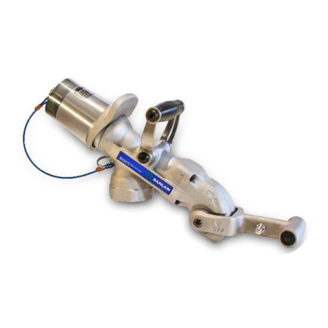
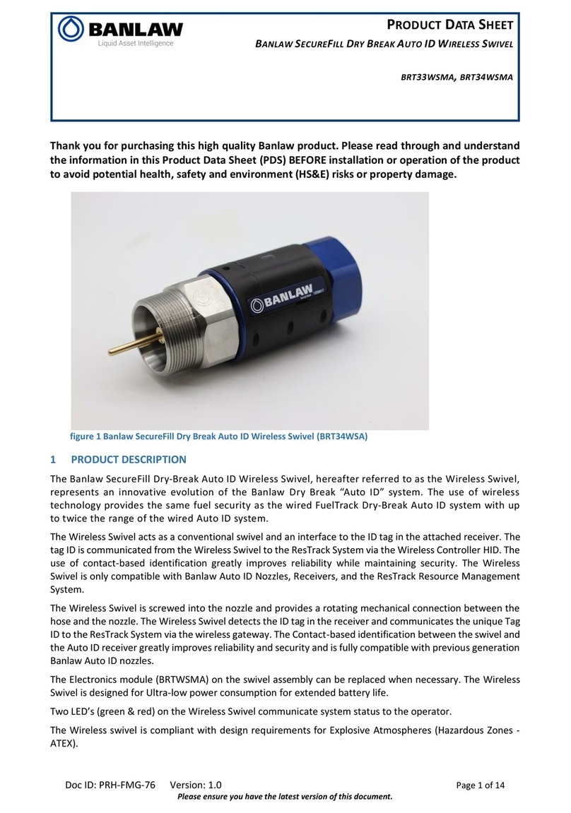
BANLAW ResTrack BFTAC Series User manual

PRODUCT DATA SHEET
BFTAC Series
Banlaw Fuel Management
Banlaw ResTrack™ Advanced Controller
Doc ID: PRH-FMG-21 Version: 1.0 Page 1of 20
Please ensure you have the latest version of this document.
Thank you for purchasing this high quality Banlaw product. Please read through and understand
the information in this Product Data Sheet BEFORE installation or operation of the product to
avoid potential health safety and environment (HS&E) risks or property damage.
Figure 1: Advanced Controller
1. PRODUCT DESCRIPTION
The Banlaw ResTrack™Advanced Controller provides both the control and the data that will ensure your
optimal use of resources and identify asset liquid-cost profiles. While the controller may be used for a range
of industrial liquids, this document willin the main, refer to hydrocarbon fuels.
The Advanced Controller is the key device to manage fluid resources. Supervised by the Banlaw
ResTrack™ software and with a range of options to control and measure fluid from delivery to storage and
then from storage to dispensing to vehicles or other items of plant.
The ResTrack software collects and stores data on all aspects of fluid receival and usage, these liquid
movements are called transactions. This data can be used for:
•Accounts
•Purchasing
•Management
•Stock Control
•Maintenance
The data will improve productivity by reducing fluid loss, reducing fluid contamination and leading to more
efficient and safer resource management outcomes with accurate reconciliation of fluid assets.

BANLAW PRODUCT DATA SHEET RESTRACK ADVANCED CONTROLLER
Doc ID: PRH-FMG-21 Version: 1.0 Page 2of 20
Please ensure you have the latest version of this document.
Figure 2: Banlaw ResTrack™Advanced Controller System Architecture
The ResTrack Advanced Controller is ruggedly constructed for use in mining and other harsh industrial
environments. The Controller unit may be mounted on a Banlaw Depot pedestal (BFTE series) or on other
infrastructure (see Figure 3). For security, the stainless-steel cabinet door-latch may be locked with an 8 mm
shackle padlock. The system is capable of controlling and monitoring fluids from delivery, via control valves
and pumps to storage tanks. Accuracy of fluid measurement is assured by temperature compensation and
supervised overfill protection may be fitted to storage tanks. The front-panel touch screen allows on-the-
spot control of operation and setup, depending on the user’s access level, of the ResTrack software.
Banlaw’s Auto ID dry-break nozzles (800 and 1000 lpm options) provide high volume spill-free fluid delivery
to heavy plant while road vehicle fuel utilisation of fuel can be supervised by Card or nozzle Auto ID
verification.

BANLAW PRODUCT DATA SHEET RESTRACK ADVANCED CONTROLLER
Doc ID: PRH-FMG-21 Version: 1.0 Page 3of 20
Please ensure you have the latest version of this document.
Figure 3: ResTrack Advanced Controller deployed on site
The Banlaw ResTrackTM system provides a complete solution to fluid management using electrical,
mechanical and computer-based components and subsystems.
The Advanced Controller is an intelligent fluid tracking unit. It is typically installed at each refuelling facility
and/or storage area. It ensures the following functions to the Banlaw ResTrackTM system:
•Automatic identification of users, vehicles and plant equipment: dispense only to authorised
machines/vehicles/operators
•Automatic recording of fluid deliveries and fluid dispensing
•Accurate fluid metering with temperature correction
•Secure dispensing of fluids only to authorised vehicles and users
•Storage tank level monitoring with temperature compensation: allow logistic and operations
team to evaluate levels in real time, order automatically on pre-sets levels, and schedule
deliveries
•Storage tank overfill protection
•Pump enable/disable time out
•Stock rotation
•Touch screen interface
The Advanced Controller unit has multiple electrical/electronic sub-systems incorporated inside the
enclosure. Advanced Controller configuration may vary from client to client depending on their needs and
the installation of optional equipment as required. Figure 3 illustrates the most common type of internal
configuration:

BANLAW PRODUCT DATA SHEET RESTRACK ADVANCED CONTROLLER
Doc ID: PRH-FMG-21 Version: 1.0 Page 4of 20
Please ensure you have the latest version of this document.
Figure 4: Banlaw ResTrack™Cabinet –Typical configuration
The ResTrack Controller has an industrial PC at the core. Figure 5 illustrates where important connectors
are located on that PC.
Figure 5: Banlaw ResTrack™Controller industrial PC top and bottom connector view

BANLAW PRODUCT DATA SHEET RESTRACK ADVANCED CONTROLLER
Doc ID: PRH-FMG-21 Version: 1.0 Page 5of 20
Please ensure you have the latest version of this document.
Figure 6: Advanced Controller Naming Convention and Example Plate showing Options “1342”
BFTAC Options:
COUNTRY
SPECIFICATION
1. AUSTRALIA
Controller wired to
Australian standards and
practice
AS/NZS 3000:2018
Banlaw’s Advanced Controllers are
configured using reputable
components that meet the
appropriate standards for the
location of installation.
2. US
Controller wired to US
standards (using UL489
Certified Equipment) and
practice
CARD READER
1. NONE
Not required
Based on site requirements and
preferences
2. CARDAX
Gallagher Cardax reader
installed
3. HID
HID PROXPRO reader
installed
NUMBER OF
FTPs
1. 1. off
One Fluid Transfer Point
interface
Installed FTPs are based upon the
number of devices that are
supervised by the Advanced
Controller.
Devices include nozzles*, pumps, ball
valves, tank level monitoring options.
*iButton reader provides a ‘touch’ input
for a registered fluid user.
2. 2. off
Two Fluid Transfer Point
interfaces
3. 3. off
Three Fluid Transfer Point
interfaces
4. 4. off
Four Fluid Transfer Point
interfaces
TANK
GAUGING
1. NO
Tank Gauging not required
Tank gauging is configured to
monitor up to 6 tank levels or 3 tanks
with level and temperature
compensation. Most Hart 2-wire
devices can be used.
2. YES
Tank Gauging Enabled

BANLAW PRODUCT DATA SHEET RESTRACK ADVANCED CONTROLLER
Doc ID: PRH-FMG-21 Version: 1.0 Page 6of 20
Please ensure you have the latest version of this document.
Key Advantages of the Banlaw ResTrack™Controller:
•Automatic identification of users, vehicles and plant equipment
•Automatic recording of fluid deliveries and fluid dispensing
•Accurate fluid metering with temperature compensation and bulk air elimination
•Stainless steel cabinet, providing superior durability and corrosion resistance.
•Compatible with HID and Cardax security card systems
•The FTP (Fluid Transfer Points) provide, actuator control, iButton (Auto ID) read, RTD (Resistance
Temperature Detector) input (PT100 to PT1000), one channel pulse count inputs (with a count
comparison channel option), override and alarm Inputs.
•Ethernet, 3G/4G, Wi-Fi connectivity options for VPN cloud or local communications and
configurable alarms and alerts by email.
The safe installation and subsequent operation of a Banlaw product rely on the completion
of all necessary “due diligences” for the assessment of the Banlaw product(s) being suitable
for the intended application(s). Such an assessment is best achieved through the mutual
cooperation of the supplier/OEM (Banlaw) and the customer or end-user. Once such an
assessment deems the Banlaw product(s) to be suitable, the customer or end-user shall
ensure effective “change management” applies should any prominent or influential aspect
of the application (upon which the initial assessment was based) be subject to change and
may affect the ongoing suitability (i.e. safety and proper function) of the Banlaw product.
The content of this document is not meant to override or substitute any applicable
Statutory, Regulatory, Customer/Site, etc. Health Safety and Environment (HS&E)
requirements.
All works should only be performed by trained, qualified and competent personnel who
are aware of the hazards associated with the constituent components of this installation
in addition to the system. Failure to comply with these practices may result in death,
serious bodily injury, loss of equipment and environmental damage.
A risk assessment (job hazard analysis - JHA) should be conducted PRIOR to the start of
any works or actions within this document. Whilst every effort has been made to ensure
the execution of this document represents no HS&E hazard, Banlaw takes neither
responsibility nor liability for the consequences and damages that may occur in the
execution of works within this document.
Persons conducting or otherwise involved with the execution of the works within this
document and project have an obligation to ensure that all HS&E requirements are
known and understood, and subsequently followed at all times.

BANLAW PRODUCT DATA SHEET RESTRACK ADVANCED CONTROLLER
Doc ID: PRH-FMG-21 Version: 1.0 Page 7of 20
Please ensure you have the latest version of this document.
2. PRODUCT SPECIFICATIONS
BANLAW ADVANCED CONTROLLER
Operating System
Windows
Wi-Fi
Wi-Fi b/g/n 1T1R (max. 150Mbps throughput) with WDS
support. Security: WEP, WPA/WPA2 or Radius server (TKIP/AES)
Mobile Telecommunications
Mode: 3G/4G, with 3 Bands available:
850/1900MHz, 900/2100MHz, 800/850/2100MHz
VPN
PPTP, L2TP/Ipsec
Power Requirements (Note below)
22.5-30 VDC
Touch Screen Size
35.5cm / 14in (22 cm / 8.7in for Service Trucks)
USB
USB 2.0 and 3.0
Operation Temperature Range
-25° to 50° C / -13° to 122 °F
Certification
RCM
Cabinet Material Composition
Stainless Steel
Dimensions (cabinet only)
620 x 535 x 240
Nozzle Control Capability
4 (local cabinet) + 12 (remote mount)
UPS Battery Backup
Yes up to 3 mins (to close-off current transaction)
Pulser Input Max Frequency
1.2kHz (10kHz optional)
Temperature Element for
temperature Compensation
PT100, 4 Wire
API Table 54b Temperature
Compensation
Yes
Note: A separate Electrical Distribution Panel (EDP) may be configured to supply 24 VDC to the Advanced
Controller. The EDP will be set-up for the local AC distribution e.g. 240 VDC 50Hz or 120 VAC 60Hz

BANLAW PRODUCT DATA SHEET RESTRACK ADVANCED CONTROLLER
Doc ID: PRH-FMG-21 Version: 1.0 Page 8of 20
Please ensure you have the latest version of this document.
3. INSTALLATION AND COMISSIONING GUIDELINES
This Installation and Commissioning Guide is general, and is not meant to replace or override installation
guidelines that arise out of a due diligence assessment of a Banlaw product for a specific (intended)
application.
For any installations where these limits are likely to be exceeded, contact Banlaw for assessment and
advise.
The scope of this section applies to the Banlaw ResTrack™Advanced Controller assemblies. Whilst other
products are mentioned –e.g. Level Sensors and flow meters –end-users must refer to separate Banlaw
documentation covering each product prior to installation.
3.1 Pre-Installation Guidelines
The Pre-Install guide is available as an organisational tool to aid a complete installation of a Banlaw Advanced
Controller. The Advanced Controller is in essence a computer that is connected to your fuel delivery and
dispensing hardware. It provide security in who is able to use fuel and will deny an unauthorised user. It
catches and stores information automatically which can be reported on in the future, while showing flow
totals and tank levels locally to users.
The appropriate care should be taken to position the Advanced Controller out of direct sunlight. This can only
help reliability and prolong hardware life.
The Advanced Controller screens can be susceptible to scratching and damage by sharp objects. Like most all
equipment if the screen is used in its intended manor this will prolong hardware life.
Please choose all fasteners to fit the Advanced Controllers mounting lugs and to fit pre-drilled stands. Make
certain the correct tools are used to fasten all fasteners.
The cabinet is IP65 rated from factory. Please ensure all glanding methods are IP65 or greater.
General Installation Notes:
1. Conduct a Job Hazard Analysis (JHA) prior to install to mitigate health, environmental
and equipment hazards.
2. Do NOT install any parts or modify a previous Controller Installation without
assessment and advise from Banlaw.
3. Do NOT install any parts that are damaged or are otherwise faulty.
4. Do NOT install parts which are not compatible electrically with the Banlaw ResTrack
Advanced Controller.
5. Do NOT install parts which are not approved by Banlaw.
6. Do NOT install or modify any electrical parts if you are not certified to do so.
7. Only engage threads of the same thread type. Ensure all threaded connections are
clean and in good condition. Avoid over-tightening.

BANLAW PRODUCT DATA SHEET RESTRACK ADVANCED CONTROLLER
Doc ID: PRH-FMG-21 Version: 1.0 Page 9of 20
Please ensure you have the latest version of this document.
3.2 Installation Procedure
The Banlaw Advanced Controller is designed to make refuelling safer and easier. The
Advanced Controller cannot be installed in a hazardous zone lower than zone 2. It’s
cabling, can run through or into a zone 1 or 0 area with appropriate conduit systems,
glanding and electrical barriers.
The Banlaw Advanced Controller cabinet may weigh up to 20kg. The stand for the cabinet
weighs approximately 25kg. All lifts should be aided with a mechanical lift apparatus or
carefully achieved by 2 people.
All 240VAC inputs will only be connected by a qualified electrician. All grounding should
be to site standards or a minimum of AS/NZS 3000:2007. NB Supersed by: AS/NZS
3000:2018
All mechanical work will be carried out by a qualified fitter to site standard as per supplied
Banlaw engineering detail. All pipework should comply with standard AS 4041-
2006(R2016).
Flow meters can be supplied to meet pressure requirements and flow rates for existing or
new systems. All air elimination and straining devices are to be installed to suppliers
specification and should reflect the Banlaw Engineering Piping and Instrumentation
Diagram (P&ID).
•Complete all necessary hazard mitigation, monitoring and control action as per the JHA.
•Unpack the Advanced controller and all its associated parts.
•Make a general arrangement of where the Controller will be fixed and all associated components.
•Make an assessment of where the hoses can stretch to and fall naturally. Make sure the Advanced
controller screen, e-stop buttons and temperature probes cannot be broken by the swinging
movements of fuelling hoses.
•Locate incoming power and outgoing data lines and provision both runs to the cabinet. Check the
incoming power circuit breaker and cable meets load requirements and local electrical standards. If
the required power supply is not available to the Advanced Controller or does not meet the voltage
and power requirements the site will need to provided such as service.
•Make a general assessment of where temperature probes, valves and meters are to be installed.
With all meters be wary that the gauze sieve removal is not obstructed and can be serviced. Place
all RTD where there out of the way and can’t be used as a stepping zone.
•Using the P&ID, determine the previous assessment meets the engineered solution. Mark and
remanufacture all spools that require modification. Measure all the pressure relief lines and cut
and bend those.
•Affix all the mechanical and electrical components only after all isolation procedures are complete.
•Attach all cabling as per Banlaw Electrical diagrams. Note that the outputs power for pulsers from
the FTP card inside the Advanced Controller cabinet will only output 24V. Check the specification of
the selected pulsers you are using to ensure no damage is caused by incorrect voltages.
•Perform all electrical installation inspection and qualification tests prior to energising the Advanced
Controller.

BANLAW PRODUCT DATA SHEET RESTRACK ADVANCED CONTROLLER
Doc ID: PRH-FMG-21 Version: 1.0 Page 10 of 20
Please ensure you have the latest version of this document.
3.3 Commissioning
The commissioning process comprises of in depth system documentation and procedures that are
mentioned in this document but are just in guide form.
The commissioning process of the Advanced Controller is as follows. It is meant for systems that have
passed all installation checks and are in an energised state.
•Check that the cabinet is not dented and clean on the inside. All glands are installed firmly, and blanks
installed.
•Ensure all electrical cables are well connected and the inside of the Advanced Controller is neat and
tidy.
•Check terminal numbers correspond to those inserted into the terminals.
•Nameplate installed with all the client, site and Controller information.
•Power supply output voltage is correct.
•The Advanced Controller screen should be powered up.
•Verify the touch-screen is working properly. Press each key on the screen, traversing menus and
entering pin and unit data and check if each key click produces a system response.
•Verify the FTP cards are powered up and the configuration is corrected using the DIP switches and
the led states. Make sure that the API table is downloaded to the FTP cards if temp compensation is
to be used.
•Verify card readers are operation. Swipe a card and validate the correct function of a user
identification and the PIN.
•Verify iButton operation. Validate the unit identification.
•Verify Splash-fill and Nozzle Auto-ID operation:
oConnect Auto-ID DryBreak nozzle to registered Auto-ID receiver.
oPlace Auto-ID Splash-fill nozzle near registered Auto-ID tag.
•Communication verified with ResTrack Advanced Controller:
oCheck if the Controller is visible via the site network and in the ResTrack web server.
oCorrect information showing, Controller, storages and transactions.
•Communication verified between the ResTrack Advanced Controller and the Tank Level Devices:
oReceiving values from temperatures and levels sensors.
oCorrect tank and ullages displayed for each tank.
oProbe level matches the dip level.
•Any third-party equipment configured and tested.
•With the power switched on use the override switch to determine the ball valves actuate correctly.
•Check the flow meters are reading correctly and schedule calibrations.
•Complete all commissioning documentation.
•Complete client sign off.

BANLAW PRODUCT DATA SHEET RESTRACK ADVANCED CONTROLLER
Doc ID: PRH-FMG-21 Version: 1.0 Page 11 of 20
Please ensure you have the latest version of this document.
4. PRINCIPLES OF OPERATION
The ResTrack system itself can be fully “automated” and requires no manual operation or manipulation.
Whether using a Banlaw ResTrack Advanced Controller system or a Banlaw classic depot, the installation of
the Advanced Controller requires no change to the normal operating procedure of the dry-break and splash-
fill refuelling system (i.e. the procedure by which a tank is normally refuelled).
The following process illustrates a typical operating sequence for a MANUAL fuel transaction, refuelling a
unit with the Banlaw ResTrack Advanced controller. Equipment that is damaged, leaking or otherwise unfit
for operation must not be used. Maintenance should be carried out to replace or repair faulty parts prior to
use of a diesel refuelling system.
4.1 Manual Transaction - Dispensing
To initiate a manual transaction please press the "Manual" icon on the screen:
Figure 7: Manual mode button
The screen will change to the following:
Figure 8: Manual Transaction Screen
Using the keypad, enter the unit ID and PIN number and press the "done" key then the "Next" key. If all the
details are entered correctly the next step is to choose a nozzle. Select the 1 or 2 Nozzle.
For more information please refer to the ResTrack Controller Operator’s Manual and
User’s Manual.
For more information to How to use your Banlaw Nozzle please refer to the Nozzle
documents.

BANLAW PRODUCT DATA SHEET RESTRACK ADVANCED CONTROLLER
Doc ID: PRH-FMG-21 Version: 1.0 Page 12 of 20
Please ensure you have the latest version of this document.
Figure 9: Nozzle Select Screen
Select the "Next" key and the transaction begins. The Manual transaction process is completed.
4.2 Automatic Transactions - Dispensing
The following process illustrates a typical operating sequence for an AUTOMATIC fuel dispensing transaction
refuelling a unit with Auto-ID Drybreak (heavy-vehicles) and/or the Splash-Fill (light-vehicles) the Banlaw
ResTrack Advanced Controller. Equipment that is damaged, leaking or otherwise unfit for operation must not
be used, but must instead be replaced or repaired prior to use of a diesel refuelling system.
4.2.1 Heavy Vehicles
NOTE: This procedure is general and site procedures will have precedence.
Heavy Vehicle Auto ID Refuelling
Step
Instruction
1
Move the unit into the fuelling area
2
Halt the vehicle as required by site procedures
3
Remove the receiver dust cap
4
Using a clean rag, thoroughly clean the receiver
5
Remove the nozzle from the holster, ensure the handle is locked in the OFF position, retract
the actuator and push the nozzle onto the receiver. Release the actuator to lock it on
6
Turn on the nozzle by pulling the trigger up into the ON position
7
The Auto ID will have identified the unit and the Advanced Controller screen will display the
Vehicle ID, i.e. N2 = HT468
8
The Advanced Controller should allow fuelling to commence, or press the START button to
start the pump if it’s not automated
9
After automatic shut-off, remove the nozzle by retracting the actuator. If necessary, press
the STOP button to turn off the pump The LCD will display the amount of fuel dispensed i.e.
N2 = 2347L
10
Ensure that the nozzle holster is clean prior to placing the nozzle back into the holster
11
Put the receiver cap back on to prevent contamination

BANLAW PRODUCT DATA SHEET RESTRACK ADVANCED CONTROLLER
Doc ID: PRH-FMG-21 Version: 1.0 Page 13 of 20
Please ensure you have the latest version of this document.
4.2.2 Light Vehicles
NOTE: This procedure is general and site procedures will have precedence.
Light Vehicle SecureFill Auto ID Refuelling
Step
Instruction
1
Insert Banlaw Splash Fill Nozzle into the Vehicle Fuel filler pipe.
2
If the ResTrack Advanced Controller detects an Auto ID TAG it will display “Nozzle Enabled,
display fuel digits to check LCD is working, and Please Proceed” when this has finished the
Vehicle ID will be displayed on the LCD screen e.g. N1= 224
3
ResTrack Advanced Controller will open the fuel line actuator ready for the Pump to Start
4
START the Pump
5
Dispensed Fuel is displayed on the LCD screen for the respective Nozzle e.g. L1= 43.20
6
When refuelling has completed remove the splash fill nozzle and turn OFF pump and place
nozzle on holster or bowser. ResTrack will now detect zero fuel flow and after 30 seconds
will close the fuel line actuator. The volume dispensed is displayed until a new transaction
is initiated.
4.3 Manual Transaction - Delivery
The following process illustrates a typical operating sequence for an FUEL DELIVERY fuel transaction using
the Banlaw ResTrack™Advanced Controller. Equipment that is damaged, leaking or otherwise unfit for
operation must not be used. Maintenance should be carried out to replace or repair faulty parts prior to use
of a diesel refuelling system.
Manual deliveries can be started by selecting the “DELIVERY” button.
Figure 10: Delivery button
The Manual Delivery button will prompt for a Unit ID, and Pin Number that would be allocated by the site
fuel champion. The delivery operator is required to punch in the docket/manifest number and the expected
delivery volume, which is to be delivered.
With all this information inserted press the “Done” button to start the delivery.

BANLAW PRODUCT DATA SHEET RESTRACK ADVANCED CONTROLLER
Doc ID: PRH-FMG-21 Version: 1.0 Page 14 of 20
Please ensure you have the latest version of this document.
Figure 11: Manual Delivery Screen –Step 2
Select the correct nozzle number then the “NEXT” button.
Figure 12: Manual Delivery Screen –Step 3
The transaction has now started. Open the fuel valves and turn the pumps on to complete the delivery. The
flow can be monitored on the Transaction Status screen
Figure 13: Manual Delivery Screen –Step 5

BANLAW PRODUCT DATA SHEET RESTRACK ADVANCED CONTROLLER
Doc ID: PRH-FMG-21 Version: 1.0 Page 15 of 20
Please ensure you have the latest version of this document.
4.3.1 Fluid Delivery –Direct To Storage
Liquid deliveries may be transferred from the tanker into the specified storage area by:
A. inwards flow-meter situations recording the liquid quantity, OR
B. non-metered situations where the quantity will be recorded on the delivery manifest for later
manual entry into the Banlaw Restrack system.
In situation A. above the ResTrack Advanced Controller will record the fluid being delivered into the storage
area by the delivery operator as part of the fluid transfer process. These delivery transactions will not show
any User ID or Fleet information but the date, time and quantity will be recorded by the flow meter for the
targeted storage area.
5. MAINTENANCE AND SPARE PARTS
Banlaw product warranty is void in the event:
• Non-genuine spare parts are used for product repair/servicing.
• Repairs are carried out by unauthorised personnel.
• Any attempt is made to repair/service a product deemed as non-serviceable by Banlaw.
• Products are subjected to abuse, tampering, neglect, or improper operation and maintenance.
• As per the terms and conditions of Banlaw product warranty – refer Section 8.
The following genuine Banlaw spare parts are available to suit the ResTrack Advance Controller:
BANLAW PART NO.
DESCRIPTION
000640
Power Supply UPS, input 24V, output 12,24
000747
12V Battery, 2x3 Shrink Wrap
000635
Industrial Computer
000638
Touch Screen
BFTFTP
FTP (Fluid Transfer Point)card
001061 (non US model)
000606 (US Model)
Communications Interface –Maestro module
000379
HART Gateway –HG1+
000744
Ethernet Industrial Switch
BFT158(Card reader) +
BFTE162(Cover) +
BFTE211A(Cover assembly) +
BFTEG2(Gasket)
HID Card reader system
000666
iButton identifier system
000586
Enclosure 620 x 450 x 215 SS 304
To maintain the safety, performance and reliability of Banlaw products:
•Only genuine Banlaw spare parts are to be used.
•Products should not be tampered with or modified in any manner not endorsed by
Banlaw.

BANLAW PRODUCT DATA SHEET RESTRACK ADVANCED CONTROLLER
Doc ID: PRH-FMG-21 Version: 1.0 Page 16 of 20
Please ensure you have the latest version of this document.
5.1 Preventative Maintenance
The integrity (sound working condition) of refuelling couplings and tank overfill protection systems is
critical to ensure all equipment can be operated in a safe and proper manner.
The working life of equipment depends on many factors, including the environment in which it operates.
Dusty and dirty environments are more prone to contamination. Due to the many varied operating
environments in which Banlaw equipment is used, any preventative maintenance information provided
within this document shall be used a guide –unless noted otherwise.
The ResTrack Advanced Controller contains electrical and electronic components, which are reliant on door
seals to be maintained regularly. In the event of failure of a door seal, liquid and dust ingress to the electronic
parts will definitely accelerate damaging effects to the Advanced Controllers electronics. This will eventually
cause a system malfunction of the ResTrack Advanced Controller.
The following preventative maintenance guidelines apply to the ResTrack Advanced Controller:
•Keep the Touch-screen clean.
•Avoid operating the Touch-Screen with dirty fingers, PPE and/or clothing contaminated with fuel.
•Keep the Advanced Controller cabinet clean and closed all the time.
•Keep the door seal in working condition
•Avoid operating high voltage and electromagnetic equipment near the Controller.
•Avoid powering the Controller with unstable power supplies.
•Maintain the use of the receiver Dust Cap and Nozzle Anchors and Holster.
•Remove any contamination from the dry-break Auto-ID receiver prior to connecting a Nozzle.
•Visually inspect the receiver for excessive wear and tear or damage prior to connecting a Nozzle.
•Ensure adequate controls and conditions monitoring are in place to ensure the contamination
levels (and other specifications) of your fuel supply are maintained –PREVENT inadequate quality
fuel entering your site fuel infrastructure and plant equipment.
5.2 Banlaw Site Service and Preventive maintenance
Clients can benefit from a Banlaw Service Level Agreement (SLA) to assist in the preventative and corrective
maintenance of the Advanced Controller. Other fuel and lubricant storage assets onsite can also be managed
via a Banlaw SLA for peace of mind. Clients with an SLA can focus on their core business activities and allow
experienced Banlaw technicians and engineers to help keep such infrastructure operating at optimum safety,
performance and reliability.

BANLAW PRODUCT DATA SHEET RESTRACK ADVANCED CONTROLLER
Doc ID: PRH-FMG-21 Version: 1.0 Page 17 of 20
Please ensure you have the latest version of this document.
6. TROUBLESHOOTING
This section provides troubleshooting recommendations for the Advanced Controller system and its
components when installed, operated and maintained in accordance with Banlaw guidelines.
ADVANCED CONTROLLER TROUBLESHOOTING GUIDE
ISSUE
MEANING
CHECKS
SOLUTION
No fuel dispensed
Controller display black
or display does not
change
Power outage
Check main power circuit
breaker.
Check power to pump.
Check ball valve actuation.
Maintenance to restore
power
Restore Power to pump
Restore ball valve
operation.
No power outage
Check Controller power
supply.
Controller PC has the power
led on.
Controller screen is on.
If your site allows manual
transactions, first attempt a
manual transaction using a
level one PIN.
Failing this, the system
should be placed into
override by switching on
the override Circuit Breaker
in the ResTrack Controller
Control Box.
This power up the nozzle
enable relays and allows
refuelling.
Note: security is
compromised when the
Controller is in override.
Automatic fuel transactions
will still be recorded whilst
the ResTrack Controller is in
override. However, Vehicles
not registered can fuel as
well and will create
transactions with unit as
OTHER.
No Fuel Dispensed
Nozzle is connected
and machine is
identified,
authorisation to
proceed is displayed
on the Controller
Display and Nozzle is
enabled, but no fuel is
being delivered
Control valve actuator is
not opening
Check that the control valve
is in the “Open” position.
If the electrical actuator
fails to open, check wiring is
secure.
Check the relay in the
control box that energises
the control valve is
functioning. This is denoted
by a yellow illuminated LED.
Repair replace faulty parts.
Pump circuitry has tripped
out.
Check pump circuitry.
If necessary, reset pump
circuit breakers.
No flow is being detected.
Check FTP Led state.
Cycle power to Controller.
Reload/Update FTP
firmware (*BANLAW).
Cycle Controller power.

BANLAW PRODUCT DATA SHEET RESTRACK ADVANCED CONTROLLER
Doc ID: PRH-FMG-21 Version: 1.0 Page 18 of 20
Please ensure you have the latest version of this document.
ADVANCED CONTROLLER TROUBLESHOOTING GUIDE
ISSUE
MEANING
CHECKS
SOLUTION
Nozzle won't lock into
holster or receiver
Nozzle /holster not clean.
Nozzle body can be loose.
Ball locks can be seized
through contamination.
Receiver can be badly worn
not allowing ball locks to
engage.
Check the nozzle/holster is
clean.
Check nozzle body.
Check receiver for wear.
Clean / repair / replace
holster / nozzle.
Nozzle may need to be
overhauled. Send Nozzle to
an authorised repairer.
Insufficient fuel
dispensed
Ring Tags and Pucks RF
Auto-ID only
Tag Detected has been lost.
Only with No tag detects on
at Controller: this means
tag detection is lost for
more than a few seconds.
Nozzle may have foreign
object behind retainer.
Remove nozzle and inspect
for obstruction.
Check FTP (Fluid Transfer
Point) unit led.
Check wiring from pulse to
Controller board.
Check Pulse drive
mechanism and flow meter.
Pump may be cutting out
due to restriction in flow or
problem with pump circuit.
Check filters for
obstruction/Pump circuit.
Repair wiring.
Repair Flowmeter/pulse
drive mechanism.
Reset power to Controller
to reset the FTP unit.
Clean filters/remove
obstructions.
Auto-ID Fail. No Fuel
dispensed.
Controller does not
respond.
Controller Display
blank or unreadable.
Auto-ID has failed to read
anything.
OR
The Controller has stalled.
Check Auto-ID circuit. Verify
ID tag is OK.
Repair Auto-ID.
Cycle Controller Power.
Upload/Reload Controller
Firmware (*Banlaw).
Fuel dispensed but no
litres ticking over on
Controller LCD display
Flowmeter pulses not
getting to the Controller
FTP
Check FTP (Fluid Transfer
Point) unit Dip Switch’s
Cycle power to Controller
to reset the FTP unit and
recheck led sate.
Update/Reload FTP
Firmware (*Banlaw).
Controller has Locked
up and is not
responsive
Software process has
stopped.
Internal corruption or
Service.
Check the windows task
manager and/or services
manager.
Restart Banlaw Advanced
Controller application and
services.
Reboot Banlaw Advanced
Controller.

BANLAW PRODUCT DATA SHEET RESTRACK ADVANCED CONTROLLER
Doc ID: PRH-FMG-21 Version: 1.0 Page 19 of 20
Please ensure you have the latest version of this document.
7. PRODUCT RECYCLING AND DISPOSAL
Banlaw values and supports the sustainable use of resources, and the safe, responsible and proper disposal
or recycling of all materials within its products. For a description of the principal materials within the Banlaw
Advanced Controller system, please refer to Section 1.
8. PRODUCT WARRANTY AND SERVICE
Banlaw is committed to providing quality products and services. To provide further assurance, our products
and services are backed by generous warranties.
The Banlaw ResTrack Controller is a fully serviceable productwith a serial number and traceable build history.
Please contact Banlaw or your nearest Banlaw Accredited Technical Partner for servicing. Please see
www.banlaw.com for warranty details and a full list of Banlaw Accredited Technical Partners.
Alternatively, Banlaw strongly recommends the client to purchase a Service Level Agreement (SLA) to fully
support our valued clients with software upgrades, monthly health check reporting and Helpdesk Support.
A copy of the Banlaw product warranty terms and conditions is available from Banlaw, the Banlaw website,
or your nearest authorised Banlaw agent.
END OF DOCUMENT
Table of contents
Other BANLAW Petrol Station Equipment manuals