Barber SURF RAKE 400 Parts list manual

4780 0318
SURF RAKE®
INSTRUCTION & PARTS
MANUAL
MODEL 400
___________________
MACHINE SERIAL NUMBER
CATALOG 400S47800318

4780 0318
IMPORTANT SAFETY INFORMATION
FOR SURF RAKE®OWNERS, OPERATOR EMPLOYERS
AND OPERATORS
1. Do not allow individuals to operate the Surf Rake®without first receiving personalized training and
ensuring that they have read this manual.
2. Before each operation of the Surf Rake®, make a careful visual inspection of the machine. Do not
operate if you observe damaged or missing parts, missing guards, excessive wear or unusual noise or
vibration during startup.
3. Never allow a bystander to approach the operating Surf Rake®, whether or not it is moving forward. Stop
the Surf Rake®,unless that individual is qualified and is present for the specific purpose of assisting in
the operation, maintenance or repair of the Surf Rake®.
4. Never allow a bystander to approach the operating Surf Rake®and stand under or nearthe hopperwhile
it is being raised or lowered.
5. Do not attempt to clear large obstacles from the path of the Surf Rake®by pushing them with the tractor
or the Surf Rake®. Stop the Surf Rake®, turn it off and manually remove obstacles. Seek assistance if
you cannot do so alone.
6. Never attempt to clear a jam by placing hands or any part of the body into or near the machinery which
has not been completely shut down. A jammed conveyor component can immediately jump into motion
and cause serious injury to hands or other body parts in immediate contact with the components if the
system is under hydraulic pressure.
7. Stand clear of the Surf Rake®when it is being set down on its foot stands or jack stand, to prevent
injury.
8. Follow OSHA regulations regarding hydraulic fluid, fire safety, guarding andifapplicable,lock-out/tag-out
procedures.
9. Before conducting any repairor maintenance on the Surf Rake®, ensure that the hydraulicpumpisOFF,
not just in neutral, and examine the machine carefully to assure that:
(a) No hydraulic hoses remain pressurized.
(b) No parts of the machine are suspended without being mechanically blocked or supported.
(c) All sources of power have been locked in the OFF position and tagged.
10. Never allow one person to operate the controls of the Surf Rake®while another has any part of their
body in or near a pinch point or machinery element from which a guard has been removed.
11. Stand clear of hydraulic hoses and fittings while the Surf Rake®is in operation. A sudden fitting or hose
failure can inflict serious injury.
12. Do not operate the Surf Rake®on a steep incline, extremely irregular surface or unstable surface. The
tractor and/or the Surf Rake®can capsize and cause serious injury or death to the operator or nearby
persons.
13. Never modify any part of the Surf Rake®without prior approval, in writing, from the manufacturer.
14. Never replace any components of the Surf Rake®with one which is not manufactured by H. Barber &
Sons, Inc., or listed in this manual as a proper replacement part.

4780 0318
TABLE OF CONTENTS
SURF RAKE®MODEL 400
When Ordering Parts, state the:
1. Model and serial number of your Surf Rake®.
2. Part number, description and page number.
3. Shipping and billing address.
4. Method by which shipment is to be made.
5. Full name of consignee.
6. Catalog number of this parts book (found on bottom left corner of every page).
Page
SECTION 1 – SURF RAKE®SYSTEMS AND COMPONENTS ..................................1-1
SECTION 2 – ATTACHING TO TOWING VEHICLE ..................................2-1
SECTION 3 – OPERATING THE SURF RAKE®..................................3-1
SECTION 4 – MAINTENANCE ..................................4-1
SECTION 5 – LUBRICATION CHART ..................................5-1
SECTION 6 – PARTS CATALOG AND ORDERING ..................................6-1
Conveyor .......................................................................6-2
Moldboard and Shields .......................................................................6-3
Drive Mechanism .......................................................................6-4
Sprocket Roller Assembly ……………………………………………………..6-5
Chain Case .......................................................................6-6
Hitch .......................................................................6-7
Hydraulic Lift .......................................................................6-8
Hydraulics …………………………………………………….6-8L
Hydraulic Drive with Manifold .......................................................................6-9
Hydraulic Drive with Manifold ..…………………………………………………..6-9L
Hub, Wheel, Tire .....................................................................6-10
Caster Assembly (Option) .....................................................................6-11
Finisher (Option) .....................................................................6-12a
Auto Finisher (Option) .....................................................................6-12b
Finisher Hydraulics (Option) .....................................................................6-13a
Auto Finisher Hydraulics (Option) .....................................................................6-13b
Auto Finisher Hydraulics (Option) .....................................................................6-13c
Auto Finisher Hydraulics (Option) .....................................................................6-13d
Lighting (Option) .....................................................................6-14
Hydraulic Moldboard (Option) …………………………………………………..6-15

4780 0318
BARBER SURF RAKE®MODEL 400
SECTION 1 - SURF RAKE®COMPONENTS
This instruction manual describes the different systems and components that make up theSurf Rake®. This
manual includes a maintenance, lubrication and parts ordering section. It is important that anyone operating
the Surf Rake®should read and understand this manual prior to operating the machine. All safety
procedures must be observed. Step-by-step instructions are also included to facilitate installation. The
following section describes the different systems and features of the Surf Rake®.
MECHANICAL COMPONENTS
CONVEYOR The conveyor belt rakes the material off of the beach, separates the debris from the sand,
elevates the debris up the conveyor and deposits the debris into the hopper. The speed of the conveyor is
adjustable. Proper belt tension is essential for long life of the conveyor belt chains and the conveyor belt
drive components which include rollers, sprockets and bearings. If the conveyor is loose, it will cause the
Surf Rake®to pick up less material and will hasten the wear of the Surf Rake’s®drive and conveyor
components.
MOLDBOARD The moldboard is located behind the reservoir and in front of the conveyor. It allowsdebris in
the path of the Surf Rake®to pass under it and into the adjacent area between the moldboard and conveyor
belt, where the conveyor separates the sand and lifts the debris using the back/hidden side of the
moldboard. The proper height adjustment of the moldboard is important for picking up themaximumamount
of debris per pass.
DRIVE MECHANISM The conveyor belt is supported by sets of sprockets and rollers on each side of the
frame. The bottom front shaft is the driving shaft or main shaft. The pair of sprockets on the main shaft and
the pair on the top shaft keep the conveyor belt tracking straight by guiding the chains located oneach side
of the conveyor belt. For the conveyor belt to track correctly, the tension must be the same on each side of
the conveyor belt. The top shaft moves upward to achieve correct tracking tension. Take up bolts located
under the top shaft on each side of the frame are tightened to raise the top shaft. It is very important to
evenly adjust both sides of the conveyor belt to the same tension by tightening these take up bolts. There
are two rubber roller assemblies that support the weight of the conveyor and the debris that is beingliftedup
to the hopper.
There are two idler sprocket assemblies that also support the weight of the conveyor and the debris that is
being lifted up to the hopper. There are four 8” diameter idler roller assemblies that create a smooth path of
support for the conveyor to rotate on.
SIDE GUARDS/STONE GUARDS The side guards and stone guard flaps are located
on each side of the conveyor belt. Together they guide debris up to the top of the
conveyor belt and into the bucket. Theykeep debris away from the conveyor belt chain
and drive sprockets. The side guards are fastened to the side frame with three bolts.
The stone guard flaps are fastened to the side guards with bolts which are loosened to
adjust the flaps down toward the belt as the flaps wear.
TOP SHIELD The top shield acts as a guide that prevents light weight objects from being blown out of the
side of the moving Surf Rake®. The top shield is also a safety device that prevents incidental contact with
the moving conveyor belt assembly. It is fastened to the side guard with four bolts and is taken off to adjust
the stone guard flaps.
CHAIN CASE The conveyor belt is driven by the hydraulic motor which transfers power
1
-
1
SIDE GUARDS

4780 0318
to the drive chain and the drive sprockets located inside the chain case.
Drive chain should be adjusted so that there is approximately 1/4"(6.35mm) slack but no more than
1"(25.4mm) slack midpoint between the sprockets. Adjustment is made by loosening the two bolts that
fasten the motor mount to the front tank motor bracket and tightening the adjusting bolt, which will move the
motor and attached front sprocket assembly forward. When adequate adjustment can nolongerbeachieved
in this manner, a half-link should be removed from the chain. Note: Chain tension should be ¼” minimum
(6.35 mm) and 1” maximum (25.4 mm).
BUCKET The bucket catches the debris the conveyor belt picks up. When full, the bucket is tripped,
pivoting on the lift arm and bucket bearings. There is a bucket stop on the right side, which stops the bucket
from rotating at its dumping position and prevents the bucket from spinning and over turning. When the
bucket is in its correct nesting position, the blocks should be to the bottom of the guides and slightly off the
frame.
HUB ASSEMBLY, WHEEL AND TIRE The two hub assemblies are attached to the
frame by the spindle. The hub rides on two races and bearings that can be adjusted as
they wear with the adjusting castle nut and pin. There is a refillable grease reservoir on
each hub that maintains pressure to the bearings.
Torque the lugs on the wheel and tire assemblies to 90 ft/lbs. The tires are inflated to 18
PSI. It is important that both tires be the same pressure.
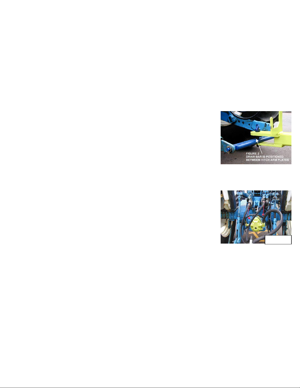
FINISHER (OPTION) The grooming finisher is attached to the rear of the Surf Rake®to
smooth the clean sand and eliminate tire marks left by the tractor and beach cleaner. Always raise the
finisher before backing up the machine.
HYDRAULIC COMPONENTS (CONVEYOR)
The conveyor hydraulic system is separate from the bucket or finisher hydraulic systems. It is a closed
system made of the following components:
A reservoir of hydraulic fluid on the front of the Surf Rake®
A hydraulic pump, attached to and powered by the tractor PTO, which circulates the hydraulic fluid
The flow control, which regulates the flow of the hydraulic fluid through the motor
The conveyor belt motor that turns the chain case drive chain and sprockets and turns the conveyor
The hydraulic fluid is then filtered and returns back to the Surf Rake®reservoir
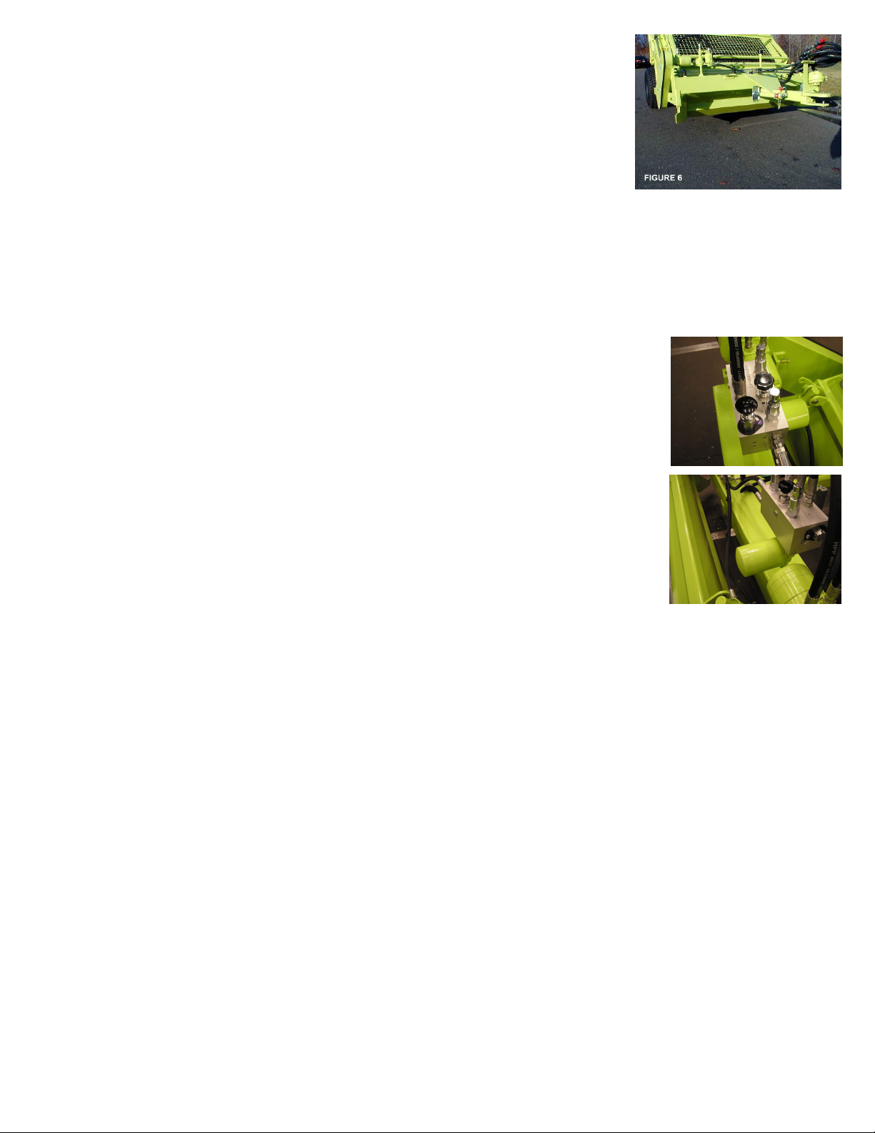
HYDRAULIC RESERVOIR The reservoir tank is located across the front of the frame. It supplies hydraulic
fluid to the hydraulic pump and conveyor belt drive motor. It has a magnetic drain on the bottomforchanging
the hydraulic fluid. There is a sight gage for inspecting hydraulic fluid level on the side of the tank.
BREATHER CAP The breather cap on top of the reservoir is pressurized to keep outcontaminantsandkeep
fumes from entering the atmosphere. It has a 10 micron rating and has a 5 PSI relief valve setting.
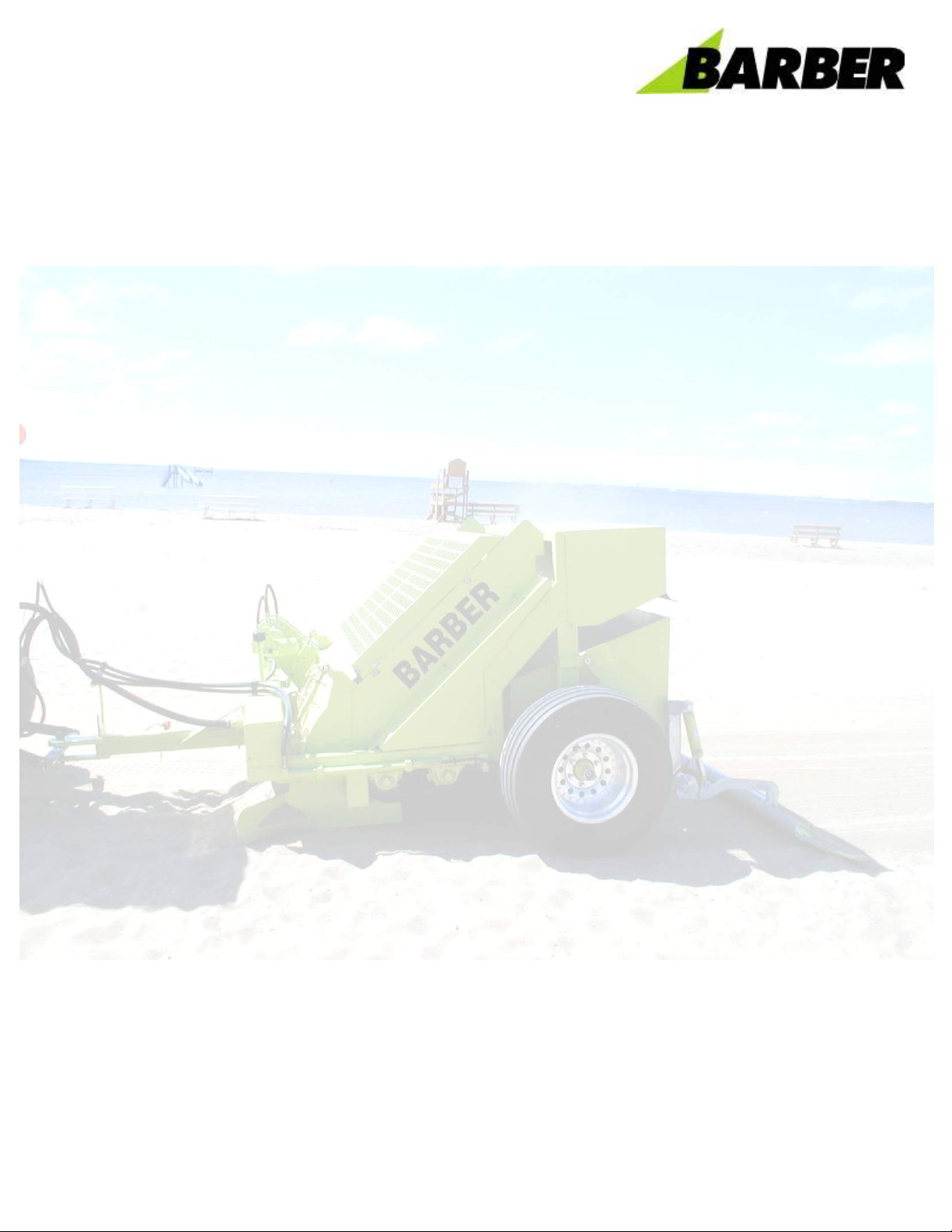
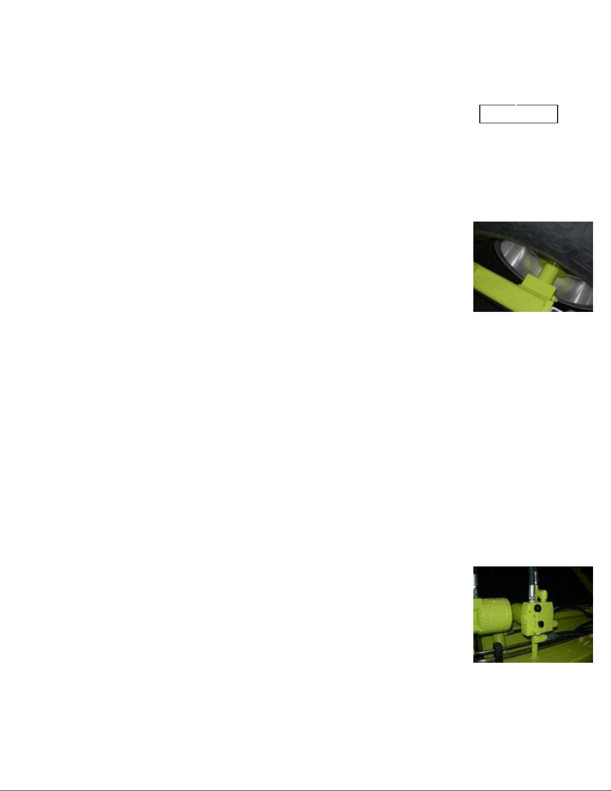
HYDRAULIC PUMP The hydraulic pump should be placed over the PTO spline shaft at
the rear of the tractor. Slide the pump as far forward as possible. The pump bracketcan
be mounted directly to the top link of the three point hitch. Adjust arms to keep the pump
upright and as close as possible to the tractor. If this bracket cannot be attached, use
the bracket with mounting chain. To secure the pump, secure the chain toarigidsurface
of the tractor, preferably to the pin of the upper three-point hitch arm bracket, so that the
torque arm of the pump is positioned up. The PTO spline will turn clockwise and the
resulting torque will tend to turn the pump clockwise also. Minimize the length of the
safety chain. There is a removable link that attaches the hook to the chain. This link may be repositioned
along the chain to minimize the chain length and maintain the upright orientation of the pump. It may be
necessary to reduce the chain length to achieve proper orientation of the pump. It may also be necessaryto
reposition the pump arm to fit up with the tractor. Be careful not to crimp or twist the hoses. If the 1"(2.54cm)
1
-
2
CHAIN TENSION
FLOW CONTROL

4780 0318
suction hose is twisted, the hose clamp on the pump end of the hose can be loosened, the hose turned to
the desired position, and the clamp re-tightened.
.
HYDRAULIC FILTER The hydraulic fluid is filtered and returned to the reservoir tank through the canister
filter.
HYDRAULIC CONVEYOR BELT MOTOR The hydraulic motor drives the
conveyor belt and is located next to the chain case. The intake hose comes
from the flow control and the outlet hose returns to the reservoir. The motor
does not run in reverse. There is a take up bolt and lock down nut at the base
of the motor that moves the motor to adjust and tighten the chain case drive
chain when the chain wears.
THE CONTROL VALVE includes an adjustable control for conveyor speed, a
reversing valve and overflow protection and
The conveyor is activated when the tractor PTO is engaged. The conveyor speed adjustment is set for
optimal cleaning. The conveyor speed can be slowed down byloosening the lock nut and turning the speed
control handle clockwise.
The automatic finisher is activated or deactivated when the PTO is engaged or disengaged. The finisher is
not affected when adjusting the conveyor speed. The finisher can be kept in the up position by closing thein
line shut off valve which is located above the hydraulic tank at the front, center of the machine. The shut off
valve is shipped in the open position for normal finisher operation.
The internal overflow valve protects the conveyor, sprockets and rollers
from objects that have become wedged. In the event that the conveyor is
stopped because of an obstruction, the reversing valve handle canbelifted
and held to reverse the conveyor direction and disentangle these objects.
Release the valve to resume normal operation.
HYDRAULIC COMPONENTS (BUCKET AND FINISHER)
The tractor’s remote valve hydraulic system is used to control both the bucket hydraulics and the finisher
hydraulics.
Each tractor remote valve spool has a pair (2) of quick disconnects that are next to each other, positioned
vertically one on top of the other, and independently operated from adjacent spools.
If a finisher option is added to the Surf Rake®, an additional spool or remote spool is needed for the finisher
raising and lowering operation (OPTIONAL).
AUTOMATIC FINISHER (OPTION) The automatic finisher is integrated into the conveyor belt hydraulics.
When the PTO on the tractor is engaged, the conveyor belt is activated and the finisher is lowered. A spring
mechanism is used to raise the finisher when the PTO is disengaged.
FINISHER CYLINDER (OPTION) The finisher’s single acting cylinder is operated hydraulically through a
hose connected to one of the tractor’s quick disconnecting remote valves. The finisher cylinder lowers the
finisher onto the beach to create a smooth pathway behind the Surf Rake®. The finisher cylinder raises the
finisher for transporting to and from either a debris dump site or dumpster and for transporting the Surf
Rake®to a storage site.
1
-
3
SHUT OFF VALVE
HYDRAULIC CONVEYOR

4780 0318
HYDRAULIC MOLDBOARD (OPTION) The hydraulic moldboard is moved up and down by two double
acting cylinders. This option requires a set of remote valves on the tractor. The two hoses connect to one
rear remote valve.
ELECTRONIC COMPONENTS (OPTIONS)
Electrical diagrams for all component options are located at the end of this manual.
POWER CABLE The towing tractor supplies the Surf Rake®and all its electronic
components with power through a seven conductor cable. The cable runs from the
tractor to the junction box on the Surf Rake®. Wiring diagrams are located at the
back of this manual – refer to the table of contents. See Picture.
LIGHTING (OPTION) The lighting circuit is comprised of left and right molded light assemblies,anelectrical
harness that connects to the towing vehicle’s lighting system. The Electrical Plug is a 7-pin configuration.
Wiring diagrams are at Section 6-14.
1
-
4
POWER CABLE

4780 0318
BARBER SURF RAKE®MODEL 400
SECTION 2 - ATTACHING TO TOWING VEHICLE
This instruction manual describes the different systems and components that make up theSurf Rake®. This
manual includes a maintenance, lubrication and parts ordering section. It is important that anyone operating
the Surf Rake®should read and understand this manual prior to operating. All safety procedures must be
observed. Step-by-step instructions are also included to facilitate installation.Thefollowingsectiondescribes
the different systems and features of the Surf Rake®.
ATTACH
DRAWBAR Install the supplied draw bar onto the tractor's lower 3-pointhitcharms,
securing it on each end with the supplied hitch bar snap pins. See Figure 2.
FRONT HITCH To attach, back the tractor up to the Surf Rake®and centrallylocate
the draw bar between the upper and lower plates of the hitch. Drop hitch pin
through and insert cotter pin into bottom of hitch pin.
DRAFT CONTROL Set the draft control on the tractor so the bottom edge of the
moldboard may be lowered at least 4 inches (10.16 cm) below ground level. The
three-point hitch lift arms on the tractor may need to be adjusted so that you have
the necessary range of movement. It is recommended that sway bars be used on the arms ofthethree-point
hitch.
HYDRAULIC PUMP The hydraulic pump should be placed over the PTO spline at
the rear of the tractor. Slide the pump as far forward on the PTO spline shaft as
possible. The pump bracket is attached to the pump. Attach the bracket to the top
pin of the three point hitch assembly. Keep the pump as close to the tractor as
possible. If the arm cannot be attached, use the attaching chain. Thepumpchainis
located in the spare parts box. Secure the chain to a rigid surface of the tractor,
preferably to the pin of the upper three-point hitch arm bracket, so that the torque
arm of the pump is positioned up. The PTO spline will turn clockwise and the
resulting torque will tend to turn the pump clockwise also. MINIMIZE THE LENGTH
OF THE SAFETY CHAIN. There is a removable link that attaches the hook to the
chain. This link may be repositioned along the chain to minimize the chain length and maintain the upright
orientation of the pump. It may be necessaryto reduce the chain length to achieve proper orientation of the
pump. Be careful not to crimp or twist the hoses. If the 1"(2.54cm) suction hose is twisted, the clamp on the
pump end of the hose can be loosened, the hose turned to the desired position, and the clamp re-tightened.
See Figure 4.
HYDRAULICS FOR CONVEYOR The conveyor belt is driven by the hydraulicmotor whichtransfers powerto
the drive chain and the drive sprockets located inside the chain case. Drive chain should be adjusted sothat
there is approximately 1/4"(6.35mm) slack but no more than 1"(25.4mm) slack midpoint between the
sprockets. Adjustment is made byloosening the two bolts that fasten the motor mount tothefronttankmotor
bracket and tightening the adjusting bolt, which will move the motor and attached front sprocket assembly
forward. When adequate adjustment can no longer be achieved in this manner, a half-link should be
removed from the chain.
HYDRAULICS FOR BUCKET RAISE Remove the protective cover (545HD-13)from thebucket hose.Attach
the hose, which is equipped with quick disconnect coupler into your tractor's quick disconnect outlet.
2-1
FIGURE 4

4780 0318
JACK POSITIONING Lift the machine up with the three-point hitch, remove the
jack stand pin and turn the jack stand back, not forward, into its neutral position
(or remove jack stand if desired). Replace jack stand pin. Fold the jackstand arm
up to keep it away from the working area as shown in Figure 6. The Surf Rake®is
now ready for operation. See Figure 6.
TRACTOR ENGINE While in operation, the tractor engine should be kept at an RPM that will result in a 540-
RPM PTO speed. This should be displayed on the tractor's tachometer. The speed of the tractor and the
PTO speed will later be adjusted to suit individual beach.
CONTROL VALVE The control valve is located between the pump and conveyor belt
motor. It raises or lowers the speed of the conveyor belt motor by regulating the flow of
hydraulic fluid circulated by the pump. The adjustable control knob is on the top, rearof
the valve. Turning the knob counter clockwise opens the valve inside and the conveyor
belt increases in speed. Turning the knob clockwise lowers the belt speed. There is a
built-in, preset, pressure relief valve that protects the conveyor belt assembly from
objects that may become wedged during cleaning. If an oversized or wedged object
stops the rotation of the conveyor belt, the valve will open, relieving pressure from the
conveyor motor and bypass the hydraulic fluid back to the reservoir. There is also a
reversing knob on the top, front of the valve. To reverse the conveyor, pull up on the
knob while the PTO is engaged. The automatic finisher is also operated from the
control valve. When the PTO is engaged, the finisher will lower to operating position
and raise when the PTO is disengaged.
CONTROL VALVE
HYDRAULIC FILTER
2-2

4780 0318
BARBER SURF RAKE®MODEL 400
SECTION 3 – OPERATING THE SURF RAKE®
OPERATION
Do not allow individuals to operate the Surf Rake®without first receiving personalized
training and ensuring that they have read this manual.
Before each operation of the Surf Rake®, make a careful visual inspection of the machine.
Do not operate if you observe damaged or missing parts, missingguards,excessivewearor
unusual noise or vibration during startup.
Stand clear of hydraulic hoses and fittings while the Surf Rake®is in operation. A sudden
fitting or hose failure can inflict serious injury.
To prevent the tractor and/or Surf Rake®from capsizing and causing serious injury or death,
do not operate the Surf Rake®on a steep incline or unstable surface.
Do not allow a bystander to approach the Surf Rake®unless that individualis qualified and
is present to assist in the operation or repair of the machine. Never allow one person to
operate the controls of the Surf Rake®while another has any part of their body in or near a
pinch point.
Under no circumstances should a bystander stand under or near the hopper whileitisbeing
dumped.
To prevent injury, do not attempt to clear large obstacles by pushing them with the tractor
or Surf Rake®.
Never attempt to clear a jam by placing hands or any part of the body into or near the
machinery that has not been completely shut down. A jammed conveyor component can
immediately jump into motion and cause serious injury to hands or other body parts in
immediate contact with the components if the system is under hydraulic pressure.
3
-
1

4780 0318
START UP Turn the handle of the flow control of the Surf Rake®down to full
speed. Pull the Surf Rake®into position on the beach area to be cleaned. Put the
tractor in gear. Engage the PTO and adjust the engine to a 540-RPM PTO setting.
With the tractor moving and the belt turning, lower the Surf Rake®into the sand.
The Surf Rake®can be towed along the beach at speeds from one to fifteen miles
per hour (1.6km/hr to 24 km/hr). Speed is dependent on the contour of the beach
and the volume of debris to be removed. On a very uneven beach or on a beach
that is heavily littered, travel-cleaning speeds of three to four miles per hour should
be maintained. On a level beach that is lightly littered, higher speeds can be
attained. The operator must be alert for large objects or obstructions on the beach.
If a significant obstruction is encountered, the Surf Rake®must be raised clear of the obstruction. If it is not
possible to safely raise the Surf Rake®clear of the obstruction, stop the machine, turn it off, and manually
remove the obstacle.
Seek assistance if you cannot do so alone.
UNDER NO CIRCUMSTANCES SHOULD THE SURF RAKE®REMOVE MORE THAN A
NEGLIGIBLE AMOUNT OF SAND.
If it is picking up too much sand, refer to the operating hints section of this manual.
The machine should be raised and lowered while cleaning to follow the general
contour of the beach. To achieve a consistently clean beach, some materialshould
be carried in front of the moldboard deflector unit. This allows the tines topenetrate
evenly for the full width of the machine, thus leveling the beach while utilizing the
Surf Rake®to its maximum potential.
MOLDBOARD ADJUSTMENT Proper adjustment of the moldboard is critical to achieving the maximum
potential from your Surf Rake®. The distance from the bottom of the Surf Rake®frame to the bottom edgeof
the moldboard is set at the factory at 7 1/4"(18.42cm). This adjustment can be varied to change thecleaning
depth and accommodate particular beach conditions. The moldboard is adjusted by two turnbuckles as
shown in Figure 10 (one side). Caution must be taken so that both sides of the moldboard are adjusted
evenly and it should be noted that even a 1/4"(.635cm) adjustment makes a significant difference in the
performance of the machine. Do Not Raise The Moldboard Too High. This will result in the Surf Rake®
unnecessarily removing sand and will greatly accelerate tine and conveyor wear. If there areanyquestions
regarding this adjustment, please call the factory for a more in-depth explanation.
3
-
2

4780 0318
OPERATING HINTS
The following general rules should be followed to attain maximum efficiency from your Surf Rake®.
If your Surf Rake®is picking up too much sand: If your Surf Rake®is not removing enough debris:
1. Lower moldboard 1. Raise moldboard
2. Reduce conveyor belt speed 2. Increase conveyor belt speed
3. Increase tractor speed 3. Decrease your tractor speed
As beach conditions vary, the adjustments listed below should also be varied. Some general conditionsand
the proper settings for the condition are also listed below:
WET SAND DRY SAND
Moldboard - lower Moldboard - raise
Belt Speed RPM's - decrease Belt Speed RPM's - increase
Tractor speed - not critical Tractor speed - not critical
FIRM BEACH SOFT BEACH
Moldboard - lower Moldboard - raise
Belt Speed RPM's - decrease Belt Speed RPM's - increase
Tractor speed - not critical Tractor speed - not critical
BIG MATERIAL SMALL MATERIAL
Moldboard - not critical Moldboard - raise
Belt Speed RPM's - decrease Belt Speed RPM's - increase
Tractor speed - slow Tractor speed - not critical
CLAY OR SOIL IN SAND PURE SAND
Moldboard - lower Moldboard - raise
Belt Speed RPM's - decrease Belt Speed RPM's - increase
Tractor speed - not critical Tractor speed - not critical
HEAVY SEAWEED BOTTLES
Moldboard - raise Moldboard - not critical
Belt Speed RPM's - decrease Belt Speed RPM's - decrease
Tractor speed - slower Tractor speed - not critical
Once the proper settings have been found, a negligible amount of sand should be removed with the
unwanted debris. After this setting has been attained, no further adjustment of the moldboard should be
required. The dailyvariations can be satisfactorily dealt with by adjusting the conveyorRPMortractorspeed.
These rules are to be used as a general guideline. Each beach is unique and requires its own group of
settings. With experience, the best settings can be found quickly allowing the Surf Rake®to be used to
its maximum potential.
3
-
3

4780 0318
BARBER SURF RAKE®MODEL 400
SECTION 4 – MAINTENANCE
To prevent injury, before conducting any repair or maintenance on the SurfRake®, ensure that
the hydraulic pump is OFF, not just in neutral, and examine the machine carefully to assure
that:
No hydraulic hoses remain pressurized
No parts of the machine are suspended without being mechanically blocked or supported.
All sources of power have been locked in the “off” position and tagged.
Follow OSHA regulations regarding hydraulic fluid, fire safety, guarding and, if applicable,
lock-out/tag-out procedures.
Always ensure that the parking brake on the tractor is set before workingon the SurfRake®to
prevent injury.
Never modify any part of the Surf Rake®without prior approval, in writing, from H. Barber &
Sons, Inc. Do not replace any component of the Surf Rake®with one that is not manufactured
by Barber or listed in this manual as a proper replacement part.
LUBRICATION
GREASE FITTINGS Lubricate all grease fittings every40 hours of operation. (See Maintenance
and Lubrication Chart - Section 5)
CHAINCASE ROLLER CHAIN Roller Chain should be oiled after every 100 hours of use.
TURNBUCKLES The Turnbuckles should be cleaned andre-greased attheendoftheseason. In
severe rusting areas this should be done more frequently.
PINS Cylinder and moldboard pins should be spot lubricated with oil every 4 weeks.
CYLINDERS Cylinder tops should be wiped clean and spot lubricated with penetrating oil every
100 hours and at the end of the season.
CONVEYOR CHAIN It is recommended that the Conveyor Chain be run dry. A dry graphite
lubricant may also be used. Occasionally, especially after a period of disuse, light penetrating oil
may be applied.
Prior to winter storage, heavier oil may be applied to avoid rusting.
4
-
1

4780 0318
BARBER SURF RAKE®MAINTENANCE ADJUSTMENTS
DAILY ADJUSTMENT CHECK There are three basic component checks for proper adjustment to ensure
that your Surf Rake®is operating to the efficiency for which it was designed. The three adjustments work
together and should be checked each time the machine is used.
1. TIRE PRESSURE It is important for the proper operation of the Surf Rake®to have the two rear tires
inflated to the same pressure.
TO ADJUST TIRE PRESSURE: Inflate tires to 18 PSI.
When the tires are not inflated the same, the tire with the lower pressure will in turn lower that side of the
Surf Rake®and cause the tines on that side to be lower. The result is the conveyor belt will clean
unevenly, possibly picking up sand on the lower side or not cleaning deep enough on the higher side.
2. CONVEYOR BELT TENSION It is important for the proper operation of the Surf Rake®tohave bothsides
of the conveyor belt with the same tension.
TO ADJUST THE CONVEYOR BELT: Open the side guard doors on both sides of the Surf Rake®. Pull
the conveyor belt back and forth midway between the upper 8” idler roller wheel and lower 8” idler roller
wheel to check for amount of play. If there is more than 1 ½” of play, tighten the adjusting bolt. This will
raise the upper shaft and tighten the conveyor assembly. Repeat this procedure on the other side of the
conveyor assembly. Take some time and go back and forth to each side of the machine, checking that
both sides are the same tension. Once both sides are the same tension, retighten the jam nutsonthetake
up bolts and refasten the doors/guards.
When the conveyor belt assembly is loose on one side, the belt will naturally sag on that side and cause
the tines to drag on that side. The result is premature wear to the tines, an uneven cleaning and possibly
picking up sand.
3. MOLDBOARD HEIGHT It is important for the proper operation of the Surf Rake®to haveboth sidesof the
moldboard adjusted identically to the same height. The moldboard is initially set evenly. For most
applications, this factory setting works well. If the factory setting is changed, be advised that a small
amount of adjustment has dramatic results. Do not move more than ¼” at a time without testing the new
setting in the sand for a period of time. Use the guides at the sides of the moldboard to align both sides
identically.
TO ADJUST: Loosen the turnbuckle locking arms on the sides to be moved. Use the guides at each side
of the moldboard to level the moldboard to the desired height. Be sure that the guides are set at the same
mark or location on each side. Retighten the turnbuckle locking arm/s.
The moldboard levels the beach so the tines can penetrate and clean the sand to a constant depth. If the
moldboard is too high on one side, the tines will be forced too deep into the sand. This will result in sand
being removed along with the debris. At no time should the Barber Surf Rake®pick up sand.
CONVEYOR BELT DRIVE COMPONENTS – INSPECTION AND ADJUSTMENT
MAIN SHAFT
MAIN SHAFT SPROCKETS Make a visual inspection of the sprockets for wear. If the sprocket toothis worn
down half of its original width, it should be replaced. There is no adjustment to be made on the sprockets.
MAIN SHAFT BEARINGS Try and lift the main shaft either with a pry bar or by hand. If there is play or
movement, an adjustment can be made to tighten the bearing.
TO ADJUST THE MAIN SHAFT BEARINGS: Unscrew machine screw on side of main shaft bearing and
4
-
2

4780 0318
remove retaining ring stop. Turn retaining ring clockwise until there is little or no play. Reinsert the stop and
screw. Do not over-tighten. The drive chain and drive sprocket must be removed to adjustthebearingonthe
chain case side. If adjusting does not remove the play from the bearing, it must be replaced.
TO REMOVE THE MAIN SHAFT BEARINGS:
Remove the top shield, side guards, and conveyor belt assemblies.
Remove the chain case cover.
Loosen the motor jam nut and take up bolt.
Loosen the motor mount bolts and slide back the motor to loosen the drive chain.
Remove drive chain.
Remove large drive sprocket.
Loosen the setscrews on the cast iron conveyor belt sprocket that is farthest away from the chain case - the
left side.
Clean the paint off of the inner/left side of the main shaft and move the left side cast iron conveyor belt
sprocket toward the center of the main shaft.
Remove the left/outer-retaining ring, which holds the cartridge bearing in its sleeve.
Pull the main shaft away from the chain case so that the left bearing slides out of its sleeve and can be
taken off of the shaft.
Remove the right inner retaining ring and push the cartridge bearing out of its sleeve.
If the cartridge bearing is locked into place, a bearing puller can be purchased to help remove the bearing.
TOP SHAFT
TOP SHAFT SPROCKETS Make a visual inspection of the sprockets for wear. If the sprocket tooth is worn
down half of its original thickness, it should be replaced. There is no adjustment to be made on the
sprockets.
TOP SHAFT BEARINGS The top shaft bearings are take-up bearings. Clean off anydebrisorexcessgrease
and visually inspect for wear or damage. Use a pry bar to check for wear pushing on the bar to inspect for
movement. If there is no movement, clean and grease. If the bearing or sprockets are visibly damaged or
have movement, they must be replaced.
TO REMOVE THE TOP SHAFT: Remove the top shield. Loosen up the four 1/2" wing nuts (518AA) that
secure the top shield to the side shields. Remove the top shield assembly by lifting it off the side shields.
REMOVE SIDE SHIELDS Remove the three 5/16” bolts that hold the side shields onto the frame.
REMOVE DRIVE CHAIN Remove the two ½” wing nuts that secure the chain case cover to the chain case.
Remove the chain case cover. Position the connecting link midway between the large and small drive
sprockets. Remove the connecting link and the drive chain.
REMOVE CONVEYOR BELT There is an overlap at the ends of the conveyor belt rubber belting. The
overlap is under one of the rows of springs. The belt must be disconnected at this overlapped row. To find
the overlap, look inside the belt while turning it. The channel on the inside of the belt will partially hide the
ends of the rubber belting, but the end of the belting will be visible. When it is found, the overlapped row
should be positioned one row up from the rear bottom sprockets.
The top shaft is a sliding/take up shaft. It is used for tensioning and loosening the conveyor belt. By
loosening the take up bolts, the top shaft will lower and the conveyor belt will loosen. Loosen the take up
bolts until the conveyor belt stops lowering (1 1/8” socket with one 12” and one 6” extension). Loosen both
sides completely.
The conveyor belt must be clamped to prevent it from rolling off/down when all fastenersandchainsfromthe
overlapped row are removed. Clamp each side using a c-clamp type vice grip or similar clamps. Remove
the row of tines that covers the overlap by removing the 3/8” bolts/nuts that secure the channels-backing
strips-retaining bars (9/16” socket with 6” extension & 9/16” box wrench).
Remove the cotter pin and connecting pin from the chains. If the chains are worn out and being replaced,
they can be torched apart.
4
-
3

4780 0318
There are 20 rows on the belt. Count 10 rows or half way from where the belt is split. A lifting chain should
be hooked at or near this midpoint location on each side of the conveyor belt. This will allow the lowest
height necessary to lift the conveyor belt off of the machine.
When the lifting chain is fastened / hooked to the conveyor belt chain and enough tension is on the lifting
chain to prevent the conveyor belt from moving, remove the clamps that prevent the conveyor belt from
rolling off/down.
Lift the conveyor belt up/off of the top shaft of the machine.
Unbolt the top shaft take up assemblyfrom each side of the machine. Loosen set screws from the bearings
and remove bearings from the top shaft.
Put the new bearings on the top shaft. Do not tighten the bearings onto the shaft yet. Do not grease the
bearings yet. Replace the top shaft assembly onto the frame. Tighten the four bolts/nuts to secure the top
shaft.
Grease the bearings until grease is visible at the seals. Wipe off any excess grease. Anyexcess grease will
immediately have sand adhering to it creating a situation where abrasion will occur.
Replace the belt using the belt removal sequence in reverse.
8” IDLER ROLLERS INSPECTION AND ADJUSTMENT
There are four 8” poly rollers that support and guide the conveyor belt on the 400. Two of the 8” poly rollers
support and guide the conveyor belt over the front of the bucket. The other two 8” poly rollers turn the belt at
the bottom of the machine, directing the belt toward the front main shaft and providing a plane of four rows
of tines that clean the sand. The internal components are the same for all rollers. Look for anywear on the
outside diameter/working surface of the roller. To check for wear, loosen the conveyorbeltbybackingoffthe
adjusting bolts located on each side under the top shaft take-up bearings. Take the weight off of the roller
you are inspecting. Check for any wobbling or play. If there is play, the bearings are worn but can be
adjusted.
TO ADJUST THE IDLER ROLLERS: Shims are used to compensate for wear. Removethebearingfromthe
machine. Remove the external retaining ring and cover from the roller. Clean the grease away from the pin
and retaining ring. Remove the retaining ring off of the pin. Add shim(s) as necessary, replace retaining ring
and recheck for play. Repeat until the roller is tight on the pin. The rollers ride on tapered rollerbearings.The
bearings will wear out prematurely if not adjusted for wear.
CHAIN CASE SPROCKETS AND CHAIN The drive chain sprockets and chain will wear with use and need
to be adjusted periodically. Remove chain case cover and check chain tightness. There shouldbe½”playin
the chain, midway between the sprockets. Check the condition of the teeth of the sprockets. If theyareworn
down to half their original thickness, they should be replaced. The chain should be replaced if the sprockets
are replaced.
TO ADJUST THE CHAIN CASE DRIVE CHAIN: Loosen the take-up bolt and nut away from the motor base
plate. Slightly loosen the two motor mount bolts to allow the motor to slide. Tighten the take-up bolt until
there is ½” play in the drive chain. Re-tighten the motor mount bolts and the take-up nut. Re-checkthechain
for correct tension. Only use dry film lubricant on the chain. Do not use grease or oil that will attract sand
and shorten the life of the components.
SKID SHOES – SOLID BELT There are two skid shoes located underneath the conveyor belt on each side
and on the inside of the side frame. There are wear blocks on each end of the conveyor belt channels that
ride on the skid shoes. The skid shoes prevent the belt from sagging while elevating the picked up debrison
its way up to the hopper. The skid shoes are made of an abrasion resistant material and must be replaced
4
-
4

4780 0318
when they wear down to a thickness of 1/8”. Inspections should be made every month to monitor the wear.
TO REMOVE THE SKID SHOES: Open the side door/guard. Tighten the conveyor belt fully to take the
weight off of the skid shoes. Do this on each side of the machine. Loosen and remove the two ½” bolts that
hold each skid shoe to the side frame arms. Note the way that the angles/brackets of the skid shoes are
situated in relation to the side frame arms. Pry the skid shoes out toward the center of the machine.
Replace with new skid shoes and fasteners. The skid shoes should sit down flush on the side frame arms
that they fasten to. A clamp may be needed to hold the skid shoes down when refastening to ensure that
they are flat on the arms. Slightly loosen the conveyor belt until there is one-inch playmidway between the
large 8” rollers.
HYDRAULIC COMPONENTS
CYLINDERS There are two single acting cylinders that trip the bucket. Hydraulic pressure from the towing
vehicle raises the cylinders and the weight of the bucket and gravity lowers them. Check for hydraulic leaks.
There are seal kits to repair leaking cylinders. A WD-40 type penetrate can be used toprevent thesealsfrom
drying out when the machine sits for the off-season. It can also lubricate the rods when first operating a
machine after it has sat for a period of time.
TO REPLACE THE CYLINDER SEALS: Power wash or clean the cylinder before removing it from the
machine. Remove hose from the cylinder. Place the base of the cylinder in a vice and position the cylinder
horizontally. Use a bar through the piston rod hole to pull out the piston and piston rod assembly.
CYLINDER DISASSEMBLY Unscrew the top with a spanner wrench. Remove the rod/piston assembly.
Never try to slide the gland over the end of the piston rod. To clean gland, remove nut on bottom of piston
rod and disassemble from that side.
Before removing seals, wipers and o-rings, take note of their orientation in the piston and gland. When
replacing felt wipers, make sure they have been saturated in oil. Coat all surfaces in oil before reassembly.
WHEELS SPINDLES AND AXLES To check for play in the spindle/hubs, elevate the wheels off of the
ground and check for play or looseness on the spindles. It is easier to determine if adjustment is necessary
when the tire/wheel is off the hub. If there is excessive play, the bearing and races should be inspected for
damage.
TO ADJUST WHEEL HUBS: Remove the buddy hub/grease reservoir from the end of the hub. Cleanaway
the grease. Remove the cotter pin. Tighten the castle nut assembly until the play is gone. Reinsertthecotter
pin and grease reservoir. There is a blue collar on the grease reservoir that extends out when grease is
added. Add grease to the reservoir until the blue collar extends out. Check for tightness of the wheel cone
nuts. They should be tightened to 95 ft/lbs. Tires should be inflated to 18 PSI.
TINE REPLACEMENT Replace tines as they break. Your machine can clean effectively with 20 or 30 tines
missing; however, it is advisable to replace them soon after they break. When a tine is broken, the work it
would normally do picking up material is transferred to the adjacent tines. This will overwork them and, in
turn, shorten their life. Never operate your machine with more than 50 broken tines. Tines will shorten as
they are used and should be replaced when they wear to within ½” of the bends.
The most convenient location for removing and replacing tines on the conveyor belts is on the top of the
machine with the top shield removed.
Position the belt. Rotate the conveyor belt slowly and stop it when the row on which you are going toreplace
the tines is conveniently located. 4-5

4780 0318
4-6
REMOVAL AND REPLACEMENT OF 504FH TINES (SIFTING BELT)
TOOLS RECOMMENDED: Safety support is REQUIRED! Power tool or ratchet, 6” socket extension and
1/2” socket (6 point), large flat blade screwdriver, 1/2” combination wrench, drive torque wrench.
The tines are secured on the retaining bar by a spacer washer and a locknut. Loosen off the retaining
washer and nut and remove the old tine. Reapply a small amount of nickel based antiseize to the
threaded stud before reassembling. Start the washer and nut back onto the threaded stud, leaving enough
room to allow the tine to be positioned underneath.
Tines should be parallel to each other and to the conveyor. Be sure the tines are positioned next to the
retaining bolt and well secured under the retaining washer and nut. Tighten the retaining nut 18 to 20 PSI.
REMOVAL AND REPLACEMENT OF 504F-1 TINES (SOLID BELT)
TOOLS RECOMMENDED: Safety support is REQUIRED! Impact gun or ratchet, 6” socket extension and
9/16” socket (6 point), large flat blade screwdriver, 9/16” combination wrench, drive torque wrench.
The tines are secured under the retaining bars (516A/516B) and kept in position by a series of divots on the
retaining bars. Loosen conveyor bolts (SIX REVOLUTIONS MAXIMUM). Bolts on both sides of any tine must
be loosened in order to remove and replace the tine. The center bolts are secured by wing nuts that will fall
to the inside of the belt if the bolts are loosened more than 6 turns. Marking the side of the 9/16" socket with
a bright colored line will allow you to count the revolutions while loosening a bolt. If a tine is to be replaced
next to the belt chain, the end bolts that secure the chain to the retaining bar must be loosened from the side
location of the machine.
Once the bolts are loosened, place the screwdriver between the retaining bar and the backing strip and next
to the tine that you are removing. Pry the retaining bar away from the belt and remove the tine. Place the
new tine under the retaining bar and resting on the backing strip, make sure that it is positioned correctly
around the divot. Torque center bolts to 22 ft.-lbs. (30 Meter-Newtons). If a torque wrench is not available,
tighten the bolts so that the retaining bars are tight against the spacer washers on which they sit. If the
retaining bars bend when tightening, back off until the retaining bar is straight. Torque end bolts to 40 ft.-lbs.
(54 Meter-Newtons).

4780 0318
Barber SURF RAKE®Model 400
Maintenance & Lubrication Schedule
Every 8 Hours or Every Day:
·Wash Machine After Use
Every 40 Hours or Every Week: Lubricate the following:
Chart Ref. # Barber Part # Description (Quantity)
1 549AS08 8” Roller Assemblies (4)
2403T Main Shaft Bearings (2)
3503VV Upper Shaft Bearings (2)
4 527GF-4 Wheel Bearings (2)
5545NN Cylinder Pins (2)
508RA Caster Arm Sleeve Bearings (2) (Optional Equipment)
530 Finisher Assembly Pins (6) (Optional Equipment)
Every 40 Hours or Every Week Inspect and/or Adjust:
Chart Ref. # Barber Part # Description (Quantity)
6 504FH Replace Broken Tines / Clear Obstructions on tines
7 404AS04 Inspect Conveyor Belt Tension (Both Sides)
8 540G Adjust Conveyor Belt Tension If Needed (Both Sides)
9 527KC Tire Pressure 18 PSI (2)
Every 200 Hours or Every 2 Months:
Chart Ref. # Barber Part # Description (Quantity)
10 522JT1 Spot Lubricate Moldboard Turnbuckle Pins (4)
11 545MM Clean Breather / Filter on Hydraulic Tank
12 545C Change Hydraulic Filter
13 503MMC Inspect and Adjust, if necessary, Main Shaft Drive Chain
14 645HYOIL Check Hydraulic Tank Fluid Level
20 442F Push flap down so it touches chain
Every 500 Hours or Once a Year:
Chart Ref. # Barber Part # Description (Quantity)
15 504G Check / Torque End Bolts on Conveyor to 40psi (40)
16 527GF-4 Adjust / Repack / Replace (if needed) Wheel Bearings
18 645HM Clean Hydraulic Tank Strainer
19 522JT Clean and Grease Moldboard Turnbuckle Assembly (2)
Every 1000 Hours or Once Every 3 Years:
Chart Ref. # Barber Part # Description (Quantity)
17 645HYOIL Change Hydraulic Fluid 10 Gal (ISO-32 Grade or Equivalent)
5
-
1

4780 0318
MAINTENANCE AND LUBRICATION CHART
5-2
INSPECT AND MAINTAIN EVERY 200 HOURS OR BIMONTHLY
INSPECT AND MAINTAIN EVERY 500 HRS OR EVERY YEAR
INSPECT AND ADJUST EVERY 40 HOURS OR EVERY WEEK
GREASE EVERY 40 HOURS OR EVERY WEEK - BOTH SIDES
INSPECT AND MAINTAIN EVERY 1000 HRS OR EVERY THREE YEARS
Table of contents
Other Barber Cleaning Equipment manuals