Barber SURF RAKE 600HD Parts list manual

61780 0221
SURF RAKE®
INSTRUCTION & PARTS
MANUAL
MODEL 600HD
___________________
MACHINE SERIAL NUMBER
CATALOG 600HDS617800221

61780 0221
IMPORTANT SAFETY INFORMATION
FOR SURF RAKE®OWNERS, OPERATOR EMPLOYERS
AND OPERATORS
1. Do not allow individuals to operate the Surf Rake®without first receiving personalized training and
ensuring that they have read this manual.
2. Before each operation of the Surf Rake®, make a careful visual inspection of the machine. Do not
operate if you observe damaged or missing parts, missing guards, excessive wear or unusual noise or
vibration during startup.
3. Never allow a bystander to approach the operating Surf Rake®, whether or not it is moving forward. Stop
the Surf Rake®,unless that individual is qualified and is present for the specific purpose of assisting in
the operation, maintenance or repair of the Surf Rake®.
4. Never allow a bystander to approach the operating Surf Rake®and stand under or nearthe hopperwhile
it is being raised or lowered.
5. Do not attempt to clear large obstacles from the path of the Surf Rake®by pushing them with the tractor
or the Surf Rake®. Stop the Surf Rake®, turn it off and manually remove obstacles. Seek assistance if
you cannot do so alone.
6. Never attempt to clear a jam by placing hands or any part of the body into or near the machinery which
has not been completely shut down. A jammed conveyor component can immediately jump into motion
and cause serious injury to hands or other body parts in immediate contact with the components if the
system is under hydraulic pressure.
7. Stand clear of the Surf Rake®when it is being set down on its foot stands or jack stand, to prevent
injury.
8. Follow OSHA regulations regarding hydraulic fluid, fire safety, guarding andifapplicable,lock-out/tag-out
procedures.
9. Before conducting any repairor maintenance on the Surf Rake®, ensure that the hydraulicpumpisOFF,
not just in neutral, and examine the machine carefully to assure that:
(a) No hydraulic hoses remain pressurized.
(b) No parts of the machine are suspended without being mechanically blocked or supported.
(c) All sources of power have been locked in the OFF position and tagged.
10. Never allow one person to operate the controls of the Surf Rake®while another has any part of their
body in or near a pinch point or machinery element from which a guard has been removed.
11. Stand clear of hydraulic hoses and fittings while the Surf Rake®is in operation. A sudden fitting or hose
failure can inflict serious injury.
12. Do not operate the Surf Rake®on a steep incline, extremely irregular surface or unstable surface. The
tractor and/or the Surf Rake®can capsize and cause serious injury or death to the operator or nearby
persons.
13. Never modify any part of the Surf Rake®without prior approval, in writing, from the manufacturer.
14. Never replace any components of the Surf Rake®with one which is not manufactured by H. Barber &
Sons, Inc., or listed in this manual as a proper replacement part.

61780 0221
TABLE OF CONTENTS
SURF RAKE®MODEL 600HD
Page
SECTION 1 – SURF RAKE®SYSTEMS AND COMPONENTS ..................................1-1
SECTION 2 – ATTACHING TO TOWING VEHICLE ..................................2-1
SECTION 3 – OPERATING THE SURF RAKE®..................................3-1
SECTION 4 – MAINTENANCE ..................................4-1
SECTION 5 – LUBRICATION CHART ..................................5-1
SECTION 6 – PARTS CATALOG AND ORDERING ..................................6-1
Conveyor “S” Belt ......................................................................6-2a
Conveyor Solid Belt ………………………………………………….6-2b
Moldboard and Shields (“S” Belt) ......................................................................6-3a
Moldboard and Shields (“S” Belt Hydraulic)..............................................................6-3b
Moldboard and Shields (Solid Belt) …………………………………………………..6-3c
Moldboard and Shields (Solid Belt Hydraulic)..........................................................6-3d
Drive Mechanism ......................................................................6-4
Chain Case ......................................................................6-5
Hitch ......................................................................6-6
Hydraulic Manifold Lift .....................................................................6-7a
Hydraulic Lift ......................................................................6-7b
Hydraulic Drive with Manifold ......................................................................6-8/6-8L
Lift Arm and Trip Mechanism ......................................................................6-9
Bucket and Chain, 3 Cu. Yd. Hopper ....................................................................6-10
Hub, Wheel, Tire, Brakes ....................................................................6-11a
Hub, Wheel, Tire ....................................................................6-11b
Roller Assembly ....................................................................6-12
Idler Roller Assembly ....................................................................6-13
Hydraulic Return ....................................................................6-14
Caster Assembly (Option) ....................................................................6-15
Finisher (Option) ....................................................................6-16a
Auto Finisher (Option) ....................................................................6-16b
Finisher Hydraulics (Option) ....................................................................6-17a
Auto Finisher Hydraulics (Option) ....................................................................6-17b
Hydraulic Multiplier (Option) ....................................................................6-18
Lighting (Option) ....................................................................6-19
Hydraulic Moldboard (Option) ....................................................................6-20
Chicago Rake (Option) ....................................................................6-21
Manual Grease System (Option) ..……………………………………………..….6-22
Pintle Attachment (Option) …..…………………………………………..….6-23
When Ordering Parts, state the:
1. Model and serial number of your Surf Rake®.
2. Part number, description and page number.
3. Shipping and billing address.
4. Method by which shipment is to be made.
5. Full name of consignee.
6. Catalog number of this parts book (found in bottom left hand corner)

61780 0221
BARBER SURF RAKE®MODEL 600HD
SECTION 1 - SURF RAKE®COMPONENTS
This instruction manual describes the different systems and components that make up theSurf Rake®. This
manual includes a maintenance, lubrication and parts ordering section. It is important that anyone operating
the Surf Rake®should read and understand this manual prior to operating the machine. All safety
procedures must be observed. Step-by-step instructions are also included to facilitate installation. The
following section describes the different systems and features of the Surf Rake®.
MECHANICAL COMPONENTS
CONVEYOR The conveyor belt rakes the material off of the beach, separates the debris from the sand,
elevates the debris up the conveyor and deposits the debris into the hopper. The speed of the conveyor is
adjustable. Proper belt tension is essential for long life of the conveyor belt chains and the conveyor belt
drive components which include rollers, sprockets and bearings. If the conveyor is loose, it will cause the
Surf Rake®to pick up less material and will hasten the wear of the Surf Rake’s®drive and conveyor
components.
MOLDBOARD The moldboard is located behind the reservoir and in front of the conveyor. It allowsdebris in
the path of the Surf Rake®to pass under it and into the adjacent area between the moldboard and conveyor
belt, where the conveyor separates the sand and lifts the debris using the back/hidden side of the
moldboard. The proper height adjustment of the moldboard is important for picking up themaximumamount
of debris per pass.
DRIVE MECHANISM The conveyor belt is supported by sets of sprockets and rollers on each side of the
frame. The bottom front shaft is the driving shaft or main shaft. The pair of sprockets on the main shaft and
the pair on the top shaft keep the conveyor belt tracking straight by guiding the chains located oneach side
of the conveyor belt. For the conveyor belt to track correctly, the tension must be the same on each side of
the conveyor belt. The top shaft moves upward to achieve correct tracking tension. Take up bolts located
under the top shaft on each side of the frame are tightened to raise the top shaft. It is very important to
evenly adjust both sides of the conveyor belt to the same tension by tightening these take up bolts. There
are four 3 ½” diameter and two 3 ¼” metal roller assemblies that support the weight of the conveyor and the
debris that is being lifted up to the hopper.
There are four 8” diameter idler roller assemblies that create a smooth path of support for the conveyor to
rotate on.
SIDE GUARDS/STONE GUARDS The side guards and stone guard flaps are located on each side of the
conveyor belt. Together they guide debris up to the top of the conveyor belt and into
the bucket. They keep debris away from the conveyor belt chain and drive sprockets.
The side guards are fastened to the side frame with three bolts. The stone guard flaps
are fastened to the side guards with bolts which are loosened to adjust the flaps down
toward the belt as the flaps wear. There should be no gap between the stone flap and
the belt. This should be adjusted every season or replaced when worn. This protects
the conveyor belt from jams.
TOP SHIELD The top shield acts as a guide that prevents light weight objects from
being blown out of the side of the moving Surf Rake®. The top shield is also a safety device that prevents
incidental contact with the moving conveyorbelt assembly. It is fastened to the sideguardwithfourboltsand
is taken off to adjust the stone guard flaps.
1
-
1
SIDE GUARDS

61780 0221
CHAIN CASE The conveyor belt is driven by the hydraulic motor which transfers
power to the drive chain and the drive sprockets located inside the chain case.
Drive chain should be adjusted so that there is approximately 1/4"(6.35mm) slack
but no more than 1"(25.4mm) slack midpoint between the sprockets. Adjustment
is made by loosening the two bolts that fasten the motor mount to the front tank
motor bracket and tightening the adjusting bolt, which will move the motor and
attached front sprocket assembly forward. Replace chain when adequate
adjustment can no longer be achieved. Note: Chain tension should be ¼”
minimum (6.35 mm) and 1” maximum (25.4 mm).
BUCKET The bucket catches the debris the conveyorbelt picks up. When full, the bucketisraisedandthen
tripped, pivoting on the lift arm and bucket bearings. There is a bucket stop on the left side, which stops the
bucket at its dumping position and prevents the bucket from spinning and over turning. There is a block on
either side of the bucket which nests into the angled guides on each side of the bucket on the frame. When
the bucket is in its correct position, the blocks should be to the bottom of the guides and slightly off the
frame.
BUCKET LIFTING MECHANISM The lift arms attach the bucket to the frame. They are elevated
hydraulically by the two larger lifting cylinders. They lift the bucket back/away from theframeforemptying the
collected debris. The lift arms are supported by a sleeve bearing located at the top of the sideframeoneach
side of the Surf Rake®. The grease port on top of the side frames should be greased weekly to prevent the
sleeve bearings from freezing up.
BUCKET TRIPPING MECHANISM After the bucket is raised, it is tripped to emptythe collected debris. It is
tripped by the smaller pair of dumping cylinders, dumping sprockets and turnbuckle assemblies. After the
bucket is tripped and emptied of debris, it must be un-tripped before it is lowered.
BUCKET GUIDES The guides are located on the frame on either side of the bucket and should be used to
position the bucket correctly bytightening or loosening the dump chains. If the bucket chain assemblies are
loose when they are down, the turnbuckles should be tightened until the chain assemblies are both taut and
lifting the bucket blocks slightly off of the frame. This adjustment should be done when the bucket is empty.
If the bucket blocks are not nested near the bottom of the guides, the dump chains are too tight. The
turnbuckles must be loosened until the chain assemblies are both taut and lifting the bucket blocks slightly
off of the frame.
HUB ASSEMBLY, WHEEL AND TIRE The two hub assemblies areattachedtothe frame
by the spindle. The hub rides on two races and bearings that can be adjusted as they
wear with the adjusting castle nut and pin. There is a refillable grease reservoir on each
hub that maintains pressure to the bearings.
Torque the lugs on the wheel and tire assemblies to 95 ft/lbs. The tires are inflated to 18
PSI. It is important that both tires be the same pressure.
AUTOMATIC FINISHER (OPTION) The grooming finisher is attached to the rear of the Surf Rake®to
smooth the clean sand and eliminate tire marks left by the tractor and beach cleaner.
HYDRAULIC COMPONENTS (CONVEYOR)
The conveyor hydraulic system is separate from the bucket or finisher hydraulic systems. It is a closed
system made of the following components:
A reservoir of hydraulic fluid on the front of the Surf Rake®
A hydraulic pump, attached to and powered by the tractor PTO, which circulates the hydraulic fluid
The flow control, which regulates the flow of the hydraulic fluid through the motor
The conveyor belt motor that turns the chain case drive chain and sprockets and turns the conveyor
The hydraulic fluid is then filtered and returns back to the Surf Rake®reservoir.
1
-
2
CHAIN TENSION

61780 0221
HYDRAULIC RESERVOIR The reservoir tank is located across the front of the frame. It supplies hydraulic
fluid to the hydraulic pump and conveyor belt drive motor. It has a magnetic drain on the bottomforchanging
the hydraulic fluid. There is a sight gage for inspecting hydraulic fluid level on the side of the tank.
BREATHER CAP The breather cap on top of the reservoir is pressurized to keep outcontaminantsandkeep
fumes from entering the atmosphere. It has a 10 micron rating and has a 5 PSI relief valve setting.
HYDRAULIC PUMP The hydraulic pump should be placed over the PTO spline shaft at the rear of the
tractor. Slide the pump as far forward as possible. The pump bracket can be mounted directlyto the toplink
of the three point hitch. Adjust arms to keep the pump upright and as close as possible to the tractor. If this
bracket cannot be attached, use the bracket with mounting chain. To secure the pump, securethechaintoa
rigid surface of the tractor, preferably to the pin of the upper three-point hitch arm bracket, so that thetorque
arm of the pump is positioned up. The PTO spline will turn clockwise and the resulting torquewilltendtoturn
the pump clockwise also. Minimize the length of the safety chain. There is a removable link thatattachesthe
hook to the chain. This link may be repositioned along the chain to minimize the chain length and maintain
the upright orientation of the pump. It may be necessary to reduce the chain length to achieve proper
orientation of the pump. It may also be necessary to reposition the pump arm to fit up with the tractor. Be
careful not to crimp or twist the hoses. If the 1"(2.54cm) suction hose is twisted, the hose clamp on the
pump end of the hose can be loosened, the hose turned to the desired position, and the clamp re-tightened.
FLOW CONTROL The flow control is located between the pump and conveyor belt
motor. It raises or lowers the speed of the conveyor belt motor by regulating the flow of
hydraulic fluid circulated by the pump. The control arm is on the side. When the control
arm is in the up position, hydraulic fluid is completely restricted, preventing the motor
and conveyor belt from turning. As the control arm is turned down, the valve inside is
opened up and the motor and conveyor belt increase speed. There is a built-in, preset,
pressure relief valve that protects the conveyor belt assembly. If an oversized object
stops the rotation of the conveyor belt, the valve will open, relieving pressure from the
conveyor motor and bypass the hydraulic fluid back to the reservoir.
HYDRAULIC FILTER The hydraulic fluid is filtered and returned to the reservoir tank through the canister
filter.
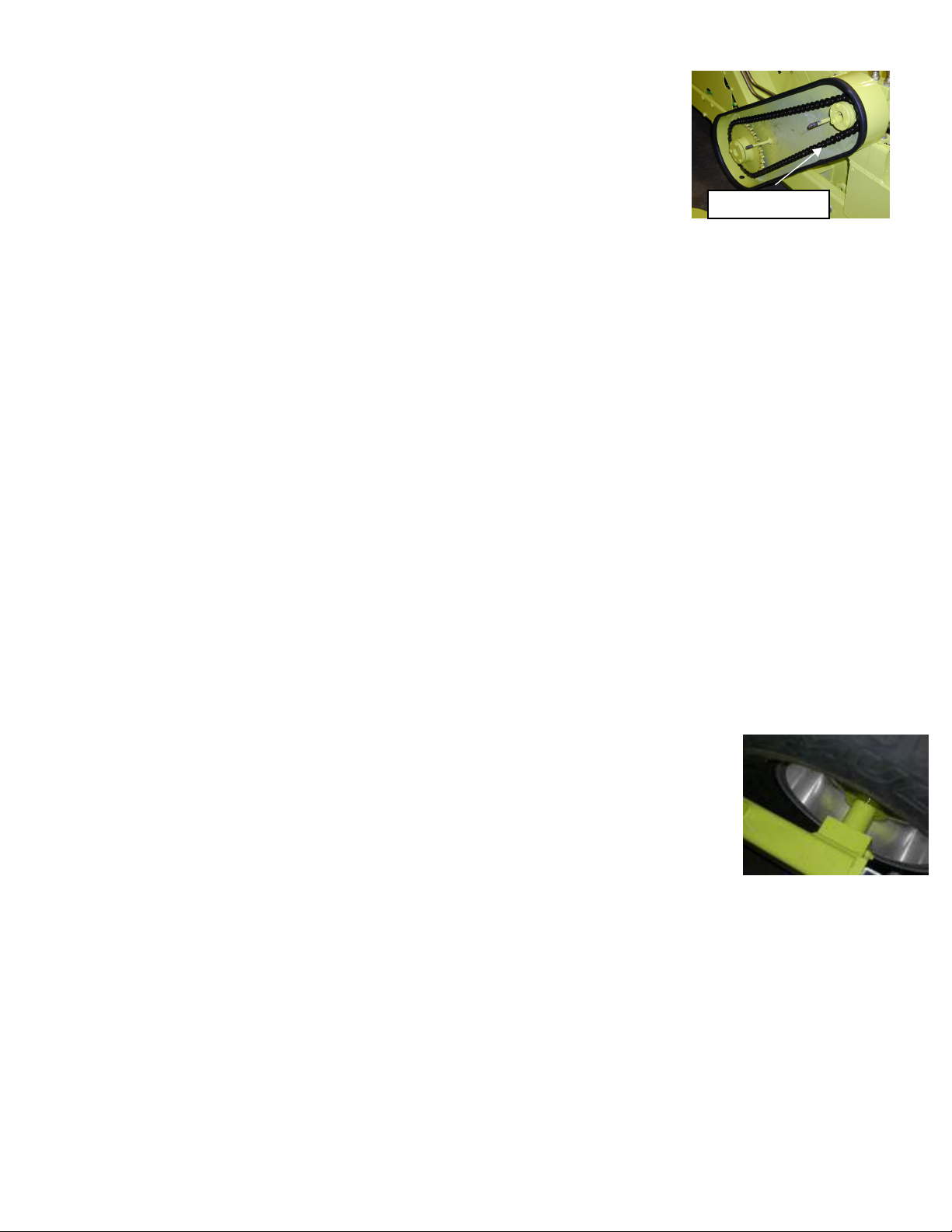
HYDRAULIC CONVEYOR BELT MOTOR The hydraulic motor drives the conveyor belt and is located next
to the chain case. The intake hose comes from the flow control and the outlet hose
returns to the reservoir. The motor does not run in reverse. There is a takeup bolt and
lock down nut at the base of the motor that moves the motor to adjust and tighten the
chain case drive chain when the chain wears.
HYDRAULIC COMPONENTS (BUCKET AND FINISHER)
The tractor’s remote valve hydraulic system is used to control both the bucket
hydraulics and the hydraulic moldboard if equipped.
Each tractor remote valve spool has a pair (2) of quick disconnects that are next to each other, positioned
either vertically or horizontally depending on brand of tractor, and independently operated from adjacent
spools. One spool (2 quick disconnect outlets) is needed for the hose for the bucket raising and lowering
operation and tripping and returning operations. Only one quick connect is utilized. No other hose or
implement can be plugged into the unused quick connect. If a hydraulic moldboard option is added, an
additional spool or second remote is required to raise and lower the moldboard. These are the onlydouble
acting cylinders on the Surf Rake®and use both the upper and lower quick disconnects of a spool. It is not
possible to share two of these operations on the same spool or set of remote valves. When connecting to
each spool use the upper remote and leave the lower remote empty.
1
-
3
CONTROL VALVE
CONVEYOR MOTOR

61780 0221
BUCKET LIFTING CYLINDERS The two large cylinders raise the lift arms and bucket to its dumping position.
BUCKET TRIPPING CYLINDERS After the hopper is raised and positioned, two small cylinders areusedto
trip the hopper and remove the debris. The dump chains, sprockets and small cylinders trip the bucket after
it is raised. The turnbuckles are the mechanism used to adjust the position of the bucket. It is very important
that the turnbuckles be adjusted evenly to distribute or share the lifting load of the bucket. When the bucket
is being raised or when the bucket is down in the cleaning position, the dump chains should be taut on both
sides.
AUTOMATIC FINISHER (OPTION) The automatic finisher is integrated into the conveyor belt hydraulics.
When the PTO on the tractor is engaged, the conveyor belt is activated and the finisher is lowered. A spring
mechanism is used to raise the finisher when the PTO is disengaged.
FINISHER CYLINDER (OPTION) The finisher’s single acting cylinder is operated hydraulically through a
hose connected to one of the tractor’s quick disconnecting remote valves. The finisher cylinder lowers the
finisher onto the beach to create a smooth pathway behind the Surf Rake®. The finisher cylinder raises the
finisher for transporting to and from either a debris dump site or dumpster and for transporting the Surf
Rake®to a storage site.
HYDRAULIC MOLDBOARD (OPTION) The hydraulic moldboard is moved up and down by two double
acting cylinders. This option requires a separate set of remote valves on the tractor. The two hoses connect
to one rear remote valve.
ELECTRONIC COMPONENTS (OPTIONS)
Electrical diagrams for all component options are located at the end of this manual.
POWER CABLE The towing tractor supplies the Surf Rake®and all its electronic
components with power through a seven conductor cable. The cable runs from the
tractor to the junction box on the Surf Rake®. Wiring diagrams are located at the
back of this manual – refer to the table of contents. See Picture.
LIGHTING (OPTION) The lighting circuit is comprised of a two piece molded
electrical harness that connects the brake lights, tail lights, turn signal lights
to the towing vehicle’s lighting system. The Electrical Plug is a 7-pin configuration. Wiring diagrams are in
Section 6-18.
HYDRAULIC MULTIPLIER (OPTION) When the tractor needs an additional valve(s) to
operate the bucket or the finisher, a hydraulic multiplier can be used. Connect the
multiplier’s solenoid body to the tractor’s quick disconnect remote outlet. Attach the
multiplier’s push button handle onto the tractor remote’s handle and plug into the
tractor’s electrical power source. This electronic solenoid activated valve spits an
existing line from the tractor, allowing you to choose which cylinders you want to
activate by pressing the button on the handle. A one to two line multiplier and a one
to three line multiplier are available.See Picture.
1
-
4
POWER CABLE
HYDRAULIC
MULTIPLIER

61780 0221
BARBER SURF RAKE®MODEL 600HD
SECTION 2 - ATTACHING TO TOWING VEHICLE
ATTACH
DRAWBAR Install the supplied draw bar onto the tractor's lower 3-pointhitcharms,
securing it on each end with the supplied hitch bar snap pins.
FRONT HITCH To attach, back the tractor up to the Surf Rake®and centrallylocate
the draw bar between the upper and lower plates of the hitch. Drop hitch pin
through and insert cotter pin into bottom of hitch pin. See Figure 2.
DRAFT CONTROL Set the draft control on the tractor so the bottom edge of the
moldboard may be lowered at least 4 inches (10.16 cm) below ground level. The
three-point hitch lift arms on the tractor may need to be adjusted so that you have
the necessary range of movement. It is recommended that sway bars be used on the arms ofthethree-point
hitch. The draw bar must be 4-5 inches from the ground at its lowest point.
HYDRAULIC PUMP The tractor PTO guard must first be removed in order to
correctly install the pump. The hydraulic pump should be placed over the PTO
spline at the rear of the tractor. Slide the pump as far forward on the PTO spline
shaft as possible. The pump bracket is attached to the pump. Attach the bracket to
the top pin of the three point assembly. Keep the pump as close to the tractor as
possible. If the arm cannot be attached, use the attaching chain. Thepumpchainis
located in the spare parts box. Secure the chain to a rigid surface of the tractor,
preferably to the pin of the upper three-point hitch arm bracket, so that the torque
arm of the pump is positioned up. The PTO spline will turn clockwise and the
resulting torque will tend to turn the pump clockwise also. MINIMIZE THE LENGTH
OF THE SAFETY CHAIN. There is a removable link that attaches the hook to the chain. This link may be
repositioned along the chain to minimize the chain length and maintain the upright orientation of thepump.It
may be necessary to reduce the chain length to achieve proper orientation of the pump. Be careful not to
crimp or twist the hoses. If the 1"(2.54cm) suction hose is twisted, the clamp on the pump end of the hose
can be loosened, the hose turned to the desired position, and the clamp re-tightened. The supplied bracket
is adjustable for a variety of tractors.
There is one hose at the front of the Surf Rake®that operates the bucket. See Figure 4.
If equipped, can add an additional hose for the hydraulic moldboard.
HYDRAULICS FOR BUCKET RAISE Remove the protective covers (545HD-13)
from the bucket hose. Attach the hose, which is equipped with quick disconnect
couplers into your tractor's quick disconnect outlets. This hosemustbeconnected
to separate spools for independent operation. DO NOT ACTIVATE TRIP UNTIL
THE BUCKET HAS BEEN RAISED.
HYDRAULIC MULTIPLIER Depending on which options are purchased for the
SURF RAKE®, the towing tractor may require more than one hydraulic (spool)
valve. If more than one valve is required, a “hydraulic multiplier” can be installed to split one
valve into two or three circuits. See Figure 5.
JACK POSITIONING Lift the machine up with the three-point hitch, remove the jack stand pin and turn the
jack stand back, not forward, into its neutral position (or remove jack stand if desired). Replace jack stand
2
-
1
FIGURE 4

61780 0221
pin. Fold the jack stand arm up to keep it away from the working area as shown in
Figure 6. The Surf Rake®is now ready for operation. See Figure 6.
TRACTOR ENGINE While in operation, the tractor engine should be kept at an RPM that will result in a 540-
RPM PTO speed. This should be displayed on the tractor's tachometer. The speed of the tractor and the
PTO speed will later be adjusted to suit individual beaches.
FLOW CONTROL The flow control valve lever should be adjusted once the PTO
on the tractor is engaged. The pump will deliver oil to the flow control valve. The
lever on the valve regulates the conveyor belt speed. Adjust the belt speed as
described in the operation section in this manual (Belt speed of 14 RPM is a good
initial setting). The valve is also equipped with an overflow relief, factory set to
2000 PSI (13,788 kPa), which serves as a safety device should the belt
mechanism jam. See Figure 7.
2-2

61780 0221
BARBER SURF RAKE®MODEL 600HD
SECTION 3 – OPERATING THE SURF RAKE®
OPERATION
Do not allow individuals to operate the Surf Rake®without first receiving personalized
training and ensuring that they have read this manual.
Before each operation of the Surf Rake®, make a careful visual inspection of the machine.
Do not operate if you observe damaged or missing parts, missingguards,excessivewearor
unusual noise or vibration during startup.
Stand clear of hydraulic hoses and fittings while the Surf Rake®is in operation. A sudden
fitting or hose failure can inflict serious injury.
To prevent the tractor and/or Surf Rake®from capsizing and causing serious injury or death,
do not operate the Surf Rake®on a steep incline or unstable surface.
Do not allow a bystander to approach the Surf Rake®unless that individualis qualified and
is present to assist in the operation or repair of the machine. Never allow one person to
operate the controls of the Surf Rake®while another has any part of their body in or near a
pinch point.
Under no circumstances should a bystander stand under or near the hopper whileitisbeing
raised or lowered.
To prevent injury, do not attempt to clear large obstacles by pushing them with the tractor
or Surf Rake®.
Never attempt to clear a jam by placing hands or any part of the body into or near the
machinery that has not been completely shut down. A jammed conveyor component can
immediately jump into motion and cause serious injury to hands or other body parts in
immediate contact with the components if the system is under hydraulic pressure.
3
-
1

61780 0221
START UP Pull the Surf Rake®into position on the beach area to be cleaned. Put the tractor in gear.
Engage the PTO and adjust the engine to a 540-RPM PTO setting. With the tractor
moving and the belt turning, lower the Surf Rake®into the sand. The Surf Rake®
can be towed along the beach at speeds from one to fifteen miles per hour
(1.6km/hr to 24 km/hr). Speed is dependent on the contour of the beach and the
volume of debris to be removed. On a very uneven beach or on a beach that is
heavily littered, travel-cleaning speeds of three to four miles per hour should be
maintained. On a level beach that is lightly littered, higher speeds can be attained.
The operator must be alert for large objects or obstructions on the beach. If a
significant obstruction is encountered, the Surf Rake®must be raised clear of the
obstruction. If it is not possible to safely raise the Surf Rake®clear of the obstruction, stop the machine,turn
it off, and manually remove the obstacle.
Seek assistance if you cannot do so alone.
UNDER NO CIRCUMSTANCES SHOULD THE SURF RAKE®REMOVE MORE THAN A
NEGLIGIBLE AMOUNT OF SAND.
If it is picking up too much sand, refer to the operating hints section of this manual.
The machine should be raised and lowered while cleaning to follow the general
contour of the beach. To achieve a consistently clean beach, some materialshould
be carried in front of the moldboard deflector unit. This allows the tines topenetrate
evenly for the full width of the machine, thus leveling the beach while utilizing the
Surf Rake®to its maximum potential.
MOLDBOARD ADJUSTMENT Proper adjustment of the moldboard is critical to
achieving the maximum potential from your Surf Rake®. The distance from the
bottom of the Surf Rake®frame to the bottom edge of the moldboard is set at the
factory at 7 1/4"(18.42cm). This adjustment can be varied to change the cleaning
depth and accommodate particular beach conditions. The moldboardisadjustedby
two turnbuckles as shown in Figure 10 (one side). Caution must be taken so that
both sides of the moldboard are adjusted evenly and it should be noted that even a
1/4"(.635cm) adjustment makes a significant difference in the performance of the
machine. Do Not Raise The Moldboard Too High. This will result in the Surf
Rake®unnecessarily removing sand and will greatly accelerate tine and conveyor wear. If there are any
questions regarding this adjustment, please call the factory for a more in-depth explanation.
3
-
2

61780 0221
OPERATING HINTS
The following general rules should be followed to attain maximum efficiency from your Surf Rake®.
If your Surf Rake®is picking up too much sand: If your Surf Rake®is not removing enough debris:
1. Lower moldboard 1. Raise moldboard
2. Reduce conveyor belt speed 2. Increase conveyor belt speed
3. Increase tractor speed 3. Decrease your tractor speed
As beach conditions vary, the adjustments listed below should also be varied. Some general conditionsand
the proper settings for the condition are also listed below:
WET SAND DRY SAND
Moldboard - lower Moldboard - raise
Belt Speed RPM's - decrease Belt Speed RPM's - increase
Tractor speed - not critical Tractor speed - not critical
FIRM BEACH SOFT BEACH
Moldboard - lower Moldboard - raise
Belt Speed RPM's - decrease Belt Speed RPM's - increase
Tractor speed - not critical Tractor speed - not critical
BIG MATERIAL SMALL MATERIAL
Moldboard - not critical Moldboard - raise
Belt Speed RPM's - decrease Belt Speed RPM's - increase
Tractor speed - slow Tractor speed - not critical
CLAY OR SOIL IN SAND PURE SAND
Moldboard - lower Moldboard - raise
Belt Speed RPM's - decrease Belt Speed RPM's - increase
Tractor speed - not critical Tractor speed - not critical
HEAVY SEAWEED BOTTLES
Moldboard - raise Moldboard - not critical
Belt Speed RPM's - decrease Belt Speed RPM's - decrease
Tractor speed - slower Tractor speed - not critical
Once the proper settings have been found, a negligible amount of sand should be removed with the
unwanted debris. After this setting has been attained, no further adjustment of the moldboard should be
required. The dailyvariations can be satisfactorily dealt with by adjusting the conveyorRPMortractorspeed.
These rules are to be used as a general guideline. Each beach is unique and requires its own group of
settings. With experience, the best settings can be found quickly allowing the Surf Rake®to be used to
its maximum potential.
3
-
3

61780 0221
BARBER SURF RAKE®MODEL 600HD
SECTION 4 – MAINTENANCE
To prevent injury, before conducting any repair or maintenance on the SurfRake®, ensure that
the hydraulic pump is OFF, not just in neutral, and examine the machine carefully to assure
that:
No hydraulic hoses remain pressurized
No parts of the machine are suspended without being mechanically blocked or supported.
All sources of power have been locked in the “off” position and tagged.
Follow OSHA regulations regarding hydraulic fluid, fire safety, guarding and, if applicable,
lock-out/tag-out procedures.
Always ensure that the parking brake on the tractor is set before workingon the SurfRake®to
prevent injury.
Never modify any part of the Surf Rake®without prior approval, in writing, from H. Barber &
Sons, Inc. Do not replace any component of the Surf Rake®with one that is not manufactured
by Barber or listed in this manual as a proper replacement part.
LUBRICATION
GREASE FITTINGS Lubricate all grease fittings every40 hours of operation. (See Maintenance
and Lubrication Chart - Section 5)
BUCKET CHAINS should be sprayed with penetrating oil twice a year. Cover the chains with oil
or grease before storing for the off-season.
CHAIN CASE ROLLER CHAIN should be oiled after every 200 hours of use.
TURNBUCKLES should be cleaned and re-greased at the end of the season. In severe rusting
areas this should be done more frequently.
PINS Cylinder and moldboard pins should be spot lubricated with oil every 4 weeks.
CYLINDERS Cylinder tops should be wiped clean and spot lubricated with penetrating oil every
100 hours and at the end of the season.
CONVEYOR CHAIN It is recommended that the Conveyor Chain berun dry. Lubricants will case
sand to adhere and speed up wear. A dry graphite lubricant may also be used. Occasionally,
especially after a period of disuse, light penetrating oil may be applied. Prior to winter storage,
heavier oil may be applied to avoid rusting.
4
-
1

61780 0221
BARBER SURF RAKE®MAINTENANCE ADJUSTMENTS
DAILY ADJUSTMENT CHECK There are four basic component checks for proper adjustment toensurethat
your Surf Rake®is operating to the efficiencyfor which it was designed. The four adjustments worktogether
and should be checked each time the machine is used.
1. TIRE PRESSURE It is important for the proper operation of the Surf Rake®to have the two rear tires
inflated to the same pressure.
TO ADJUST TIRE PRESSURE: Inflate tires to 18 PSI.
When the tires are not inflated the same, the tire with the lower pressure will in turn lower that side of the
Surf Rake®and cause the tines on that side to be lower. The result is the conveyor belt will clean
unevenly, possibly picking up sand on the lower side or not cleaning deep enough on the higher side.
2. BUCKET / LIFT ARM CHAIN ASSEMBLIES It is important for the proper operation of the Surf Rake®to
have the bucket/lift arm chains on each side of the Surf Rake®under the same tension, and not left loose,
so they will share the load when lifting and tripping the hopper.
TO ADJUST BUCKET CHAINS: When the bucket is sitting on the frame, the chain/turnbuckleassemblies
should be tight. Tighten up loose chain/turnbuckle assemblies so that both sides have the same tension
and the bucket support blocks are just off or barely touching the frame.
When one chain assembly is loose while raising the bucket, all the weight and pressureofliftingthe
bucket is shifted to the tighter chain assembly. This causes the tighter chain assembly to stretch
more than it would if both chain assemblies were the same tension. This causes premature wear to
the links and the chains and can cause sudden failure to one or both of the chain assemblies. If
both chains become loose, the bucket will not fully return to the forward/bottom position and will
bottom out farther back on the frame than it should. This will allow a gap between the bucket and
the path of the debris being thrown by the conveyor that allows the debris to drop down in front of
the bucket.
3. CONVEYOR BELT TENSION It is important for the proper operation of the Surf Rake®tohave bothsides
of the conveyor belt with the same tension.
TO ADJUST THE CONVEYOR BELT: Open the side guard doors on both sides of the Surf Rake®. Pull
the conveyor belt back and forth midway between the upper 8” idler roller wheel and lower 8” idler roller
wheel to check for amount of play. If there is more than 1 ½” of play, tighten the adjusting bolt. This will
raise the upper shaft and tighten the conveyor assembly. Repeat this procedure on the other side of the
conveyor assembly. Take some time and go back and forth to each side of the machine, checking that
both sides are the same tension. Once both sides are the same tension, retighten the jam nutsonthetake
up bolts and refasten the doors/guards.
When the conveyor belt assembly is loose on one side, the belt will naturally sag on that side and cause
the tines to drag on that side. The result is premature wear to the tines, an uneven cleaning and possibly
picking up sand.
4. MOLDBOARD HEIGHT It is important for the proper operation of the Surf Rake®to haveboth sidesof the
moldboard adjusted identically to the same height. The moldboard is initially set evenly. For most
applications, this factory setting works well. If the factorysetting is changed, be advised that a smallamount
of adjustment has dramatic results. Do not move more than ¼” at a time without testing the new setting in
the sand for a period of time. Use the guides at the sides of the moldboard to align both sides identically.
TO ADJUST: Loosen the turnbuckle locking arms on the sides to be moved. Use the guides at each side
of the moldboard to level the moldboard to the desired height. Be sure that the guides are set at the same
mark or location on each side. Retighten the turnbuckle locking arm/s.
4
-
2

61780 0221
The moldboard levels the beach so the tines can penetrate and clean the sand to a constant depth. If the
moldboard is too high on one side, the tines will be forced too deep into the sand. This will result in sand
being removed along with the debris. At no time should the Barber Surf Rake®pick up sand.
HYDRAULIC MOLDBOARD (Option) The hydraulic moldboard can be powered up ordownfromthetractor.
When the moldboard is lowered, the life of the conveyor system is maximized. By varying the height of the
moldboard, the depth of cleaning is varied.
CONVEYOR BELT DRIVE COMPONENTS – INSPECTION AND ADJUSTMENT
MAIN SHAFT
MAIN SHAFT SPROCKETS Make a visual inspection of the sprockets for wear. If the sprocket toothis worn
down half of its original width, it should be replaced. There is no adjustment to be made on the sprockets.
MAIN SHAFT BEARINGS Try and lift the main shaft either with a pry bar or by hand. If there is play or
movement, an adjustment can be made to tighten the bearing.
TO ADJUST THE MAIN SHAFT BEARINGS: Unscrew machine screw on side of main shaft bearing and
remove retaining ring stop. Turn retaining ring clockwise until there is little or no play. Reinsert the stop and
screw. Do not over-tighten. The drive chain and drive sprocket must be removed to adjustthebearingonthe
chain case side. If adjusting does not remove the play from the bearing, it must be replaced.
TO REMOVE THE MAIN SHAFT BEARINGS:
Remove the top shield, side guards, and conveyor belt assemblies.
Remove the chain case cover.
Loosen the motor jam nut and take up bolt.
Loosen the motor mount bolts and slide back the motor to loosen the drive chain.
Remove drive chain.
Remove large drive sprocket.
Loosen the set screws on the cast iron conveyor belt sprocket that is farthest awayfrom the chaincase-the
left side.
Clean the paint off of the inner/left side of the main shaft and move the left side cast iron conveyor belt
sprocket toward the center of the main shaft.
Remove the left/outer-retaining ring, which holds the cartridge bearing in its sleeve.
Pull the main shaft away from the chain case so that the left bearing slides out of its sleeve and can be
taken off of the shaft.
Remove the right inner retaining ring and push the cartridge bearing out of its sleeve.
If the cartridge bearing is locked into place, a bearing puller can be purchased to help remove the bearing.
TOP SHAFT
TOP SHAFT SPROCKETS Make a visual inspection of the sprockets for wear. If the sprocket tooth is worn
down half of its original thickness, the top shaft should be replaced. There is no adjustment to be made on
the sprockets.
TOP SHAFT BEARINGS The top shaft bearings are take-up bearings. Clean off anydebrisorexcessgrease
and visually inspect for wear or damage. Use a pry bar to check for wear pushing on the bar to inspect for
movement. If there is no movement, clean and grease. If the bearings or sprockets are visibly damaged or
have movement, they must be replaced.
TO REMOVE THE TOP SHAFT: Raise the bucket and secure it with the safety support (545JJCA).
Remove the top shield. Loosen up the six 1/2" wing nuts (518AA) that secure the top shield to the side
shields. The top shield is hinged. Flip up the lower section of the top shield so it rests on the uppersectionof
the top shield. Remove the top shield assembly by lifting it off the side shields.
4
-
3

61780 0221
REMOVE SIDE SHIELDS The side shields are slotted so that they can be lifted off the frame once the bolts
that attach them to the frame are loosened (four bolts) or removed (two bolts).
There are three 3/8” bolts on each side, which secure each guard. The top set of bolts has no hidden nuts
and loosens with either a 9/16” socket or box wrench. They can be completely removed from the frame.
The middle set of bolts has nuts, which are accessible and hidden on the inside of the frame. They should
be partially loosened with a 9/16” socket and box end wrench. Loosen three or four turns but do not remove
from the frame.
One of the bottom bolts/nuts is accessible behind the chain case and must be loosened three or four turns
with an open end wrench. The other bottom bolt can be loosened three or four turns with a 9/16” socket and
box end wrench.
Raise the bottom end of the side guard first, and then lift the guard off of the bolts.
Remove the two ½” wing nuts that secure the chain case cover to the chain case. Remove the chain case
cover. Position the connecting link midway between the large and small drive sprockets. Remove the
connecting link and the drive chain.
The tractor can be unoccupied from the SURF RAKE®at this point.
There is an overlap at the ends of the conveyor belt rubber belting. The overlap is under one of the rows of
springs. The belt must be disconnected at this overlapped row. To find the overlap, look inside thebelt while
turning it. The channel on the inside of the belt will partially hide the ends of the rubber belting, but theendof
the belting will be visible. When it is found, the overlapped row should be positioned one row up from the
rear bottom sprockets.
Loosen the jam nuts on the take up bolts (1 1/8" open ended wrench), which are located behind the
small/upper side door shields on both sides of the machine.
The top shaft is a sliding/take up shaft. It is used for tensioning and loosening the conveyor belt. By
loosening the take up bolts, the top shaft will lower and the conveyor belt will loosen. Loosen the take up
bolts until the conveyor belt stops lowering (1 1/8” socket with one 12” and one 6” extension). Loosen both
sides completely.
The conveyor belt must be clamped to prevent it from rolling off/down when all fastenersandchainsfromthe
overlapped row are removed. Clamp each side using a c-clamp type vice grip or similarclamps. Position the
clamps through the chain and fasten the clamps to the arms that hold the skid shoes. Remove the row of
tines that covers the overlap by removing the 5/16” nuts that secure the channels-backing strips-retaining
bars (use a 1/2” socket with 6” extension & 9/16” box wrench).
Remove the cotter pin and connecting pin from the chains. If the chains are worn out and being replaced,
they can be torched apart.
There are 28 rows on the belt. Count 14 rows or half way from where the belt is split. A lifting chain should
be hooked at or near this midpoint location on each side of the conveyor belt. This will allow the lowest
height necessary to lift the conveyor belt off of the machine.
When the lifting chain is fastened/hooked to the conveyor belt chain and enough tension is on the lifting
chain to prevent the conveyor belt from moving, remove the clamps that prevent the conveyor belt from
rolling off/down.
Lift the conveyor belt up/off of the machine being careful of the cylinders at the top of the machine and of the
hydraulics at the front of the machine.
The conveyor belt can also be pulled off from the rear of the machine.
Once the belt is off, the top shaft lifts up the guides and off the frame. It is easiest to have two people lift it
off. It must be lifted off straight and even.
4
-
4

61780 0221
It is important to make a note of the bearing location on the top shaft to ensure correct placement of the new
bearings. Measure the distance from the edges of the bearings to the ends of the shaft and to the edge of
the sprockets. The better centered the sprockets are the smoother the belt will run.Thebearings canonlygo
on one way. The collars must face the outside.
It is possible to rotate the top shaft to allow the unused side of the sprocket teeth to be in contact with the
conveyor belt chain, prolonging the life of the top shaft.
Loosen the set screws on the bearings and pull the bearings off the top shaft. It usually takes a bearing
puller to remove the bearings. Mark a centering hole on the shaft to keep the bearing puller straight. Clean,
file or sand any imperfections that will prevent the bearing replacement.
Put the new bearings on the top shaft. Do not tighten the bearings onto the shaft yet. Do not grease the
bearings yet. Replace the top shaft assembly into the take-up guides of the frame. This is a short two-man
step. Each person should be on the ends of the shaft. The first person should position one bearing into the
take-up guides and just start it down the guides. The second person should use a large screwdriver to help
position the second bearing into the take-up guides. When both sides are in the guides, let the top shaft
assembly drop all the way down the guides. A rubber hammer will help to get the shaft down the guides.
Center the shaft/sprockets so they are even on both sides. Tighten down the set screws when the top shaft
is centered.
Grease the bearings until grease is visible at the seals. Wipe off any excess grease. Anyexcess grease will
immediately have sand adhering to it creating a situation where abrasion will occur.
Replace the belt using the belt removal sequence in reverse.
3 ½” and 3 ¼” ROLLERS AND 8” IDLER ROLLERS INSPECTION AND ADJUSTMENT
There are four 3 ½” steel rollers, two3 ¼” rollers and four 8” poly rollers that support and guide the conveyor
belt on the 600HD. The 3 ½” and 3 ¼” rollers are used to support the conveyor chains. Two of the 8” poly
rollers support and guide the conveyor belt over the front of the bucket. The other two 8” poly rollers turn the
belt at the bottom of the machine, directing the belt toward the front main shaft and providing a plane of four
rows of tines that clean the sand. The internal components are the same for all rollers. Look for any wear on
the outside diameter/working surface of the roller. On the metal rollers there will be grooves fromthecontact
with the conveyor chains. If there are flats on the metal roller it must be replaced. To check for wear, loosen
the conveyor belt by backing off the adjusting bolts located on each side under the top shaft take-up
bearings. Take the weight off of the roller you are inspecting. Check for anywobbling or play. If thereisplay,
the bearings are worn but can be adjusted.
TO ADJUST THE IDLER ROLLERS: Shims are used to compensate for wear. Removethebearingfromthe
machine. Remove the external retaining ring and cover from the roller. Clean the grease away from the pin
and retaining ring. Remove the retaining ring off of the pin. Add shim(s) as necessary, replace retaining ring
and recheck for play. Repeat until the roller is tight on the pin. The rollers ride on tapered rollerbearings.The
bearings will wear out prematurely if not adjusted for wear.
CHAIN CASE SPROCKETS AND CHAIN The drive chain sprockets and chain will wear with use and need
to be adjusted periodically. Remove chain case cover and check chain tightness. There shouldbe½”playin
the chain, midway between the sprockets. Check the condition of the teeth of the sprockets. If theyareworn
down to half their original thickness, they should be replaced. The chain should be replaced if the sprockets
are replaced.
TO ADJUST THE CHAIN CASE DRIVE CHAIN: Loosen the take-up bolt and nut away from the motor base
plate. Slightly loosen the two motor mount bolts to allow the motor to slide. Tighten the take-up bolt until
there is ½” play in the drive chain. Re-tighten the motor mount bolts and the take-up nut. Re-checkthechain
for correct tension. Only use dry film lubricant on the chain. Do not use grease or oil that will attract sand
and shorten the life of the components.
4
-
5

61780 0221
HYDRAULIC COMPONENTS
BUCKET MANIFOLD The bucket manifold, a sequence valve, runs the two functions of the bucket. It both
raises and trips the bucket. It is centrally located on the upper cross tube.
CYLINDERS The large and small cylinders are of similar design. They are single acting cylinders. Hydraulic
pressure from the towing vehicle raises the cylinders and the weight of the bucket and gravitylowers them.
Check for hydraulic leaks. There are seal kits to repair leaking cylinders. A WD-40 type penetrate can be
used to prevent the seals from drying out when the machine sits for the off-season. It can also lubricate the
rods when first operating a machine after it has sat for a period of time. Clean the breathers to improve
airflow in and out of the cylinders.
TO REPLACE THE CYLINDER SEALS: Power wash or clean the cylinder before removing it from the
machine. Remove hose from the cylinder. Remove breather from the cylinder. Place the base of thecylinder
in a vice and position the cylinder horizontally. Use a bar through the piston rod hole to pull out the piston
and piston rod assembly.
Small Cylinder – Have someone compress the retaining ring at the top of the cylinder while you pull the
gland and rod assembly out of the cylinder. If the retaining ring is rusted, it is advisable to use penetratingoil
and clean up the ring and adjoining area. The retaining ring ends must touch in order to disassemble. Pull
out as straight as possible.
Large Cylinder - Unscrew the top with a spanner wrench. Remove the rod/piston assembly.Nevertrytoslide
the gland over the end of the piston rod. To clean gland, remove nut on bottom of piston rod and
disassemble from that side.
Before removing seals, wipers and O-rings, take note of their orientation in the piston and gland. When
replacing felt wipers, make sure they have been saturated in oil. Coat all surfaces in oil before reassembly.
WHEELS SPINDLES AND AXLES To check for play in the spindle/hubs elevate thewheelsoff of theground
and check for play or looseness on the spindles. It is easier to determine if adjustment is necessary when
the tire/wheel is off the hub. If there is excessive play, the bearing and races should be inspected for
damage.
TO ADJUST WHEEL HUBS: Remove the buddy hub/grease reservoir from the end of the hub. Cleanaway
the grease. Remove the cotter pin. Tighten the castle nut assembly until the play is gone. Reinsertthecotter
pin and grease reservoir. There is a blue collar on the grease reservoir that extends out when grease is
added. Add grease to the reservoir until the blue collar extends out. Check for tightness of the wheel cone
nuts. They should be tightened to 95 ft/lbs. Tires should be inflated to 18 PSI.
TINE REPLACEMENT Replace tines as they break. Your machine can clean effectively with 20 or 30 tines
missing; however, it is advisable to replace them soon after they break. When a tine is broken, the work it
would normally do picking up material is transferred to the adjacent tines. This will overwork them and, in
turn, shorten their life. Never operate your machine with more than 50 broken tines. Tines will shorten as
they are used and should be replaced when they wear to within ½” of the bends.
The most convenient location for removing and replacing tines on the conveyor belts is at the back of the
machine with the bucket raised and secured with the safety support. Never work on the machinewithout the
safety support in place.
Position the belt. Rotate the conveyor belt slowly and stop it when the row on which you are going toreplace
the tines is at the top, back of the machine and parallel to the ground.
4
-
6

61780 0221
REMOVAL AND REPLACEMENT OF 504FH TINES (SIFTING BELT)
TOOLS RECOMMENDED: Safety support is REQUIRED! 3/8” ratchet, 6” socket extension and 1/2” socket
(6 point) or a 1/2” combination wrench.
The tines are secured on the retaining bar by a spacer washer and a locknut. Loosen off the retaining
washer and nut and remove the old tine. Reapply a small amount of anti-seize to the threaded stud before
reassembling. Start the washer and nut back onto the threaded stud, leaving enough room to allow the tine
to be positioned underneath.
Tines should be parallel to each other and to the conveyor. Be sure the tines are positioned next to the
retaining bolt and well secured under the retaining washer and nut. Tighten the retaining nut 18to 20 ft-lbs.
REMOVAL AND REPLACEMENT OF 504F-1 TINES (SOLID BELT)
TOOLS RECOMMENDED: Safety support is REQUIRED! Impact gun or ratchet, 6” socket extension and
9/16” socket (6 point), large flat blade screwdriver, 9/16” combination wrench, drive torque wrench.
The tines are secured under the retaining bars (516A/516B) and kept in position bya series of divots on the
retaining bars. Loosen conveyor bolts (SIX REVOLUTIONS MAXIMUM). Bolts on bothsides of anytine must
be loosened in order to remove and replace the tine. The center bolts are secured by wing nuts that will fall
to the inside of the belt if the bolts are loosened more than 6 turns. Marking the side of the 9/16" socket with
a bright colored line will allow you to count the revolutions while loosening a bolt. If a tine is to be replaced
next to the belt chain, the end bolts that secure the chain to the retaining bar must be loosenedfromtheside
location of the machine.
Once the bolts are loosened, place the screwdriver between the retaining bar and the backing strip andnext
to the tine that you are removing. Pry the retaining bar away from the belt and remove the tine. Place the
new tine under the retaining bar and resting on the backing strip, make sure that it is positioned correctly
around the divot. Torque center bolts to 22 ft.-lbs. (30 Meter-Newtons). If a torque wrench is not available,
tighten the bolts so that the retaining bars are tight against the spacer washers on which they sit. If the
retaining bars bend when tightening, back off until the retaining bar is straight. Torque end bolts to 40ft.-lbs.
(54 Meter-Newtons).
4-7

61780 0221
REMOVAL AND REPLACEMENT OF CHANNEL STUDS 560B05095S (SIFTING BELT).
TOOLS RECOMMENDED: Channel Stud Replacement Tool 504CM02, 5/8” socket or ratcheting wrench,
hammer, punch, oil. The Bucket Safety Support is REQUIRED when working at the rear of the conveyor
with the bucket elevated!
When the top of a channel stud has broken off from use, the stud must be replaced. The base of the
stud must be removed from the channel using a punch and hammer from the topside of the conveyor
belt. The washer can be reused. The replacement stud should be pushed through from the inside of the
conveyor belt. The stud’s splines can be aligned/turned into the grooves in the channel that were made
from the broken stud. Place the washer onto the stud and then thread the lightly oiled Channel Stud
Replacement Tool onto the stud by hand, as far as it will go. Tighten the tool until the head of the stud is
flush with the channel. The tool is threaded on both ends and each end will tighten between 10 -15
studs. DO NOT use power tools to install studs.
Please visit the SURF RAKE Maintenance Video Section of our website, by clicking the following link:
http://www.hbarber.com/customer-service/Maintenance/surf-rake-maintenance.html
4-8
Table of contents
Other Barber Cleaning Equipment manuals