Barry-Wehmiller Thiele Technologies Streamfeeder Reliant... User manual

Manual
Reliant 1500

Part Number: 00900323
© 2009 Thiele Technologies, Inc. - Streamfeeder. All rights reserved.
No part of this publication may be reproduced, photocopied, stored on
a retrieval system, or transmitted without the express written consent of
Thiele Technologies, Inc. - Streamfeeder.
Thiele Technologies, Inc. - Streamfeeder
103 Osborne Road
Minneapolis, MN 55432-3120 USA
Tel:763.502.0000
Fax:763.502.0100
e-Mail: service@streamfeeder.com
Web: www.streamfeeder.com
Printed in the USA.

i
Relaint 1500 Manual
Contents
Safety Information ........................................................ii
Specications ..............................................................iv
Section 1: About the Machine .......................................................1
Section2: InstallingtheMachine ..................................................7
Section3: PreparingforOperation .............................................15
Section4: HowtoOperate ...........................................................27
Section5: Troubleshooting .........................................................31
Section6: InspectionandCare ...................................................33
Section7: AdditionalWedges .....................................................41
Section8: ElectricalSchematics.................................................43
Section9: MechanicalComponents ...........................................47
ii Reliant 1500 Manual
Message
Conventions
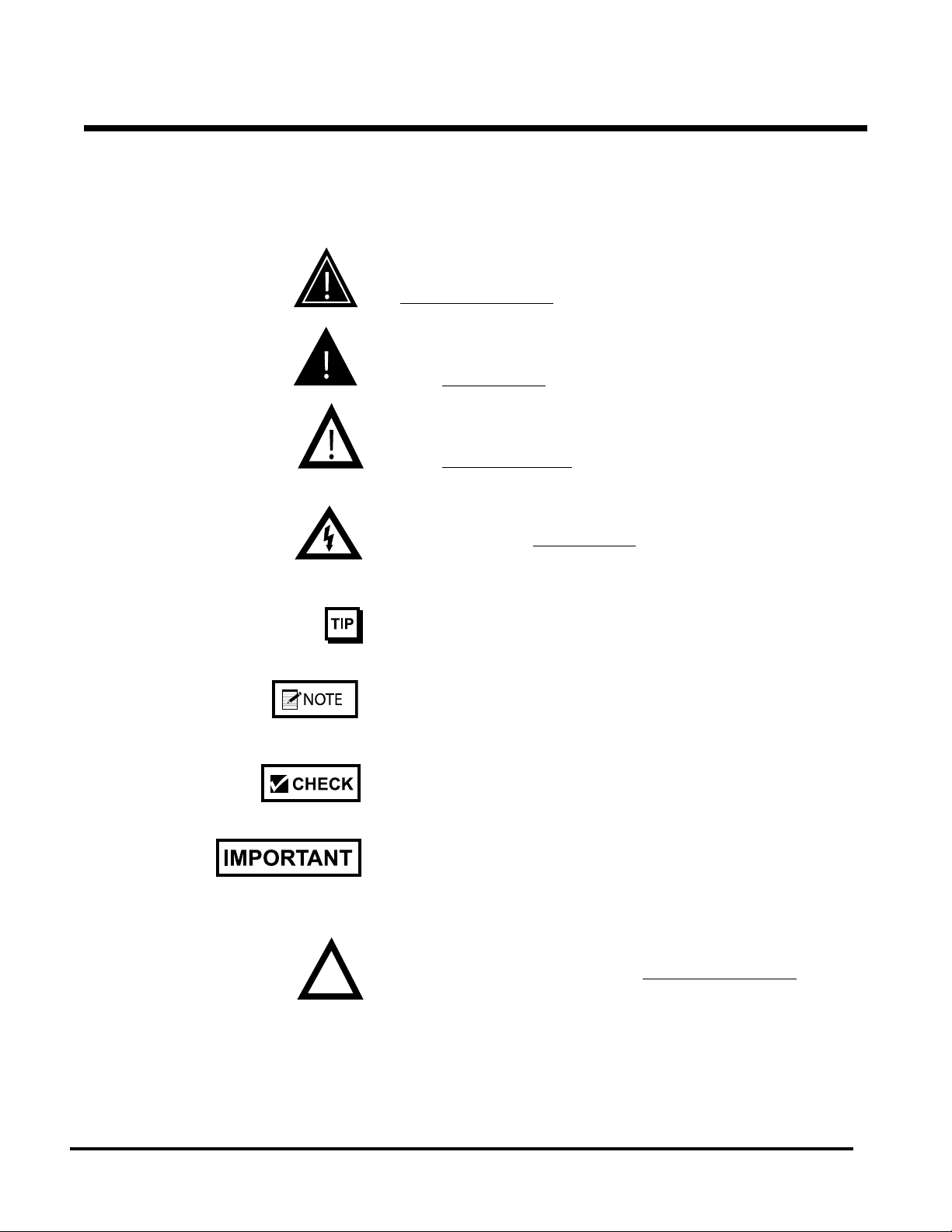
DANGER signies an action or specic equipment area that can result
in serious injury or death if proper precautions are not taken.
WARNING signies an action or specic equipment area that can
result in personal injury if proper precautions are not taken.
CAUTION signies an action or specic equipment area that can
result in equipment damage if proper precautions are not taken.
ELECTRICAL DANGER signies an action or specic equipment
area that can result in personal injury or death from an electrical haz-
ard if proper precautions are not taken.
TIP signies information that is provided to help minimize problems
in the installation or operation of the feeder.
NOTE provides useful additional information that the installer or
operator should be aware of to perform a certain task.
CHECK signies an action that should be reviewed by the operator
before proceeding.
IMPORTANT alerts the installer or operator to actions that can poten-
tially lead to problems or equipment damage if instructions are not
followed properly.
WARNING LABELS afxed to this product signify an action or spe-
cic equipment area that can result in serious injury or death if proper
precautions are not taken.
Before You Begin

iii
Relaint 1500 Manual
Message
Conventions
Before You Begin
Avoid injury. Do not reach around guards.
Hazardous voltage. Contact will cause electric shock or burn. Turn off
and lock out power before servicing.
Moving parts can crush and cut. Keep guards in place. Lock out power
before servicing.
Pinch point. Keep hands and ngers clear.
Moving parts can crush and cut. Keep guards in place. Lock out power
before servicing.

iv Reliant 1500 Manual
Maximum Product Size: ......................... 9.25 W x 6 L in (235 x 152 mm)
Contact us for longer insert length
Minimum Product Size: ...................... 2.125 W x 2.25 L in (54 x 57 mm)
Min/Max Product Thickness: ......................... .003-.25 in (.076-6.35 mm)
Belt Speed: ......................................................... 1000 ipm (25,400 mmpm)
Electrical Requirements: ................................................... 115/230vac, 1A
Weight: .............................................................................. 23 lbs. (10.43kg)
speCifiCations
1
Relaint 1500 Manual
1About the Machine
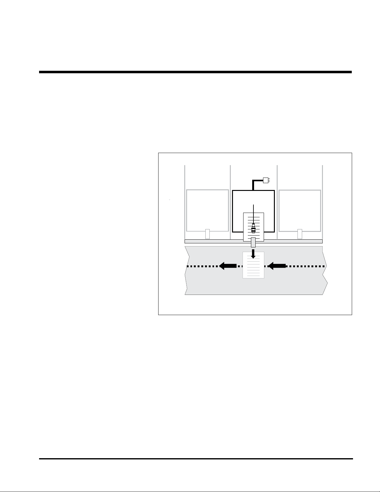
The Streamfeeder Reliant 1500 Universal Friction Feeder is designed
for use with multi-station inserters to efciently separate, singulate,
and feed a wide variety of cut sheets and non-nested material. After
material is loaded into the hopper, the rest is automatic. With photo
sensor monitoring, feed cycling is always sychronized with the in-
serter gripper jaw. Figure 1 shows a typical setup on the inserter.
Introducing the
Reliant 1500
Universal Friction
Feeder
Figure 1. Reliant 1500 Universal Friction Feeders
Mounted on an Inserter
Insert Track
Feeder x
Station x

2Reliant 1500 Manual
Product Description Section 1
One of the design features that makes the Reliant 1500 Universal Fric-
tion Feeder unique is a part called the gate assembly (Figure 2). This
patented device is the main reason the feeder can separate, singulate,
and feed individual sheets with accuracy and reliability — even at
high speeds. A single-knob adjustment allows you to easily setup the
feeder for many different types of material.
Figure 2. Standard O-Ring Gate, Horizon Adjust
Bar Gate II Horizon Adjust Assembly
The machine is entirely powered by a single AC synchronous mo-
tor that runs off of either a 120- or 240-VAC electrical power source.
Once the machine is prepared for operation, the power-up and opera-
tion of the feeder is relatively easy.
But to get the most out of your machine, you should rst become fa-
miliar with all of the features, including controls and sensors, connec-
tors, and cables.
Please read the “Main Features” subsection that follows to learn about
all controls, sensors, and connections. Once you have done this, you
should be ready to adjust and successfully run the machine with any
material within the specication parameters.
NO TE
This manual contains installation, preparation,
and operation information only.
3
Relaint 1500 Manual
Section 1 Product Description
Main Features
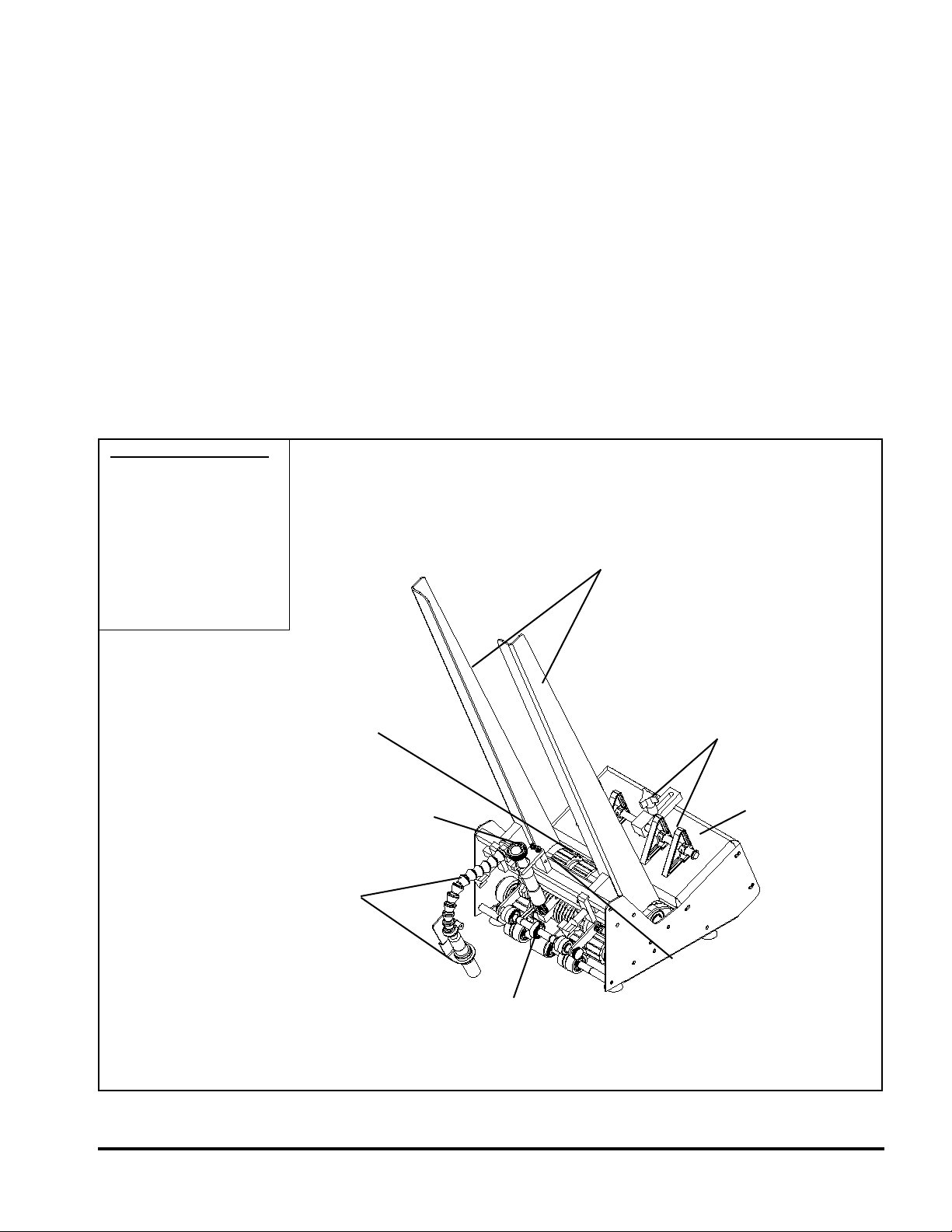
Figure 3. Reliant 1500 Universal Friction Feeder Features
Loose Parts Supplied
• Side Guides (2)
• Hold-Down Spring
Assemblies (2)
• Side Guide
Wing-Nut Assemblies (2)
• Insert Plate Guide
• AC Power Cord
Side Guides
(Adjustable)
Back Wedge and
Adjustments
Feeder
Top Panel
(Table Top)
Gate Bracket
Assembly
Discharge
Assist
Assembly
Photo Sensor
and Flex Arm
Extension
Gate Assembly
and Adjustment
Feed Belts
The Reliant 1500 Universal Friction Feeder is designed for reliability,
exibility, and ease of use. All control, sensing, and feeding assem-
blies are combined into one compact unit.
The main components and adjustments of the feeder are shown in Fig-
ure 3. Brief descriptions of each are found in Table 1 on the following
page.

4Reliant 1500 Manual
Feature Description
Gate assembly and adjustment Mounted on a gate bracket assembly directly above the feed belts, this
device provides a curvature to help preshingle stacked material. When
properly adjusted, a clearance is created to help singulate and feed
material. (Note: For multiple page material, a 1 to 1.5 maximum thickness
is typical.)
Top panel (table top) Used to support the back wedge.
Side guides (adjustable) Holds a stack of material to be fed and helps keep it straight for proper
entry through the gate assembly area. Also referred to as “hopper”.
(Note: Loading can be performed from either the front or back of inserter.)
Back wedge and adjustment Lifts the material to keep it off the table top, reduces excessive contact
with the feed belts, and helps push the material against the curvature of
the gate assembly.
Photo Sensor and ex arm extension Controls the starting and stopping of a feed cycle by sensing the presence
or absence of material. To ensure proper alignment of the sensor, a ex
arm extension allows you adjust it for proper distance and angle to the
material.
Feed belts Provides the friction and motion necessary to pull individual material from
the bottom of the stack and through the gate assembly area.
Discharge assist assembly A series of small rollers mounted on movable brackets help to gently hold
material down on the feed belts as material exits the gate assembly area.
These brackets and rollers are part of the gate assembly and are removed
when the gate assembly is removed.
On/Off switch (not pictured) Located on the rear of the feeder, this toggle switch turns AC power On or
Off to the feeder.
Hold-down spring assemblies As a piece of material exits the feeder gate assembly area, these two
hold-down spring assemblies help keep it aligned and in proper position
for the gripper jaw. Shipped loose and mounted on inserter.
Side guide wing-nut assmblies Secures side guides to the cross-bar. Loosening each allows you to move
each side guide horizontally to accommodate various material sizes.
Insert plate guide This plate is supplied with your feeder and is to be mounted on the back
deck plate. Shipped loose and mounted on inserter (if required).
AC power cord, 8 ft. (2.44 m) IEC320 removal three-prong. Shipped loose.
Product Description Section 1
Table 1. Feature Descriptions of Reliant 1500 Universal Friction Feeder

5
Relaint 1500 Manual
Controls and
Sensors
Read the following descriptions to become familiar with the controls
and sensors. See Figure 4 for locations
ON/OFF SWITCH. This rocker switch determines whether AC power
to the feeder is “On” or “Off”. Push the horizontal line (—) to turn
“On” and push the circle (O) to turn “Off”. It is located at the rear of
the feeder.
PHOTO SENSOR. Sends signals to the relay circuit to both “start”
and “stop” the feed cycle. Also called a sheet sensor, it “looks” for
the leading edge of the bottom sheet of material to stop the machine.
When the gripper jaw removes the bottom sheet of material, the feeder
starts and then feeds the next sheet. The machine stops as the sensor
“sees” the leading edge. The sensor uses two LED indicators. A green
LED functions as the power indicator and is constantly lit during
normal operation. The second LED is amber, and indicates the pres-
ence of product staged under the sensor. Amber LED on indicates the
sensor "sees" product; off when no product is present.
Read the following descriptions to become familiar with the connec-
tors and cables. Refer back to Figure 4 for location.
AC POWER INLET/FUSE. This 3-prong connector receives incom-
ing AC power from the designated power source. One end of AC
power cord plugs into power inlet (rear of machine), while the other
plugs into a three-prong grounded and fused outlet.
Connectors and
Cables
Figure 4. Feeder (Rear)
On/Off Switch
Fuse Holder
AC Power
Inlet
Connector

6Reliant 1500 Manual
7
Relaint 1500 Manual
2Installing the Machine
Installation of the Reliant 1500 Universal Friction Feeder onto the
back deck plate of an inserter is a relatively simple procedure, with
only minor modications to the selected insert station prior to attach-
ing the feeder. The entire installation can typically be done with a hex-
head driver set and a slotted screwdriver.
To install the feeder, perform the following steps:
1: Removing rear guide assembly
2: Removing T-plate
3: Repositioning separator foot
4: Removing suction cup and closing off vacuum hose
5: Repositioning insert guide tabs
Optional step: Install insert plate guide
6: Installing feeder hold-down spring assemblies
7: Aligning feeder with insert station
8: Securing feeder to inserter
9: Initial feeder photo sensor positioning
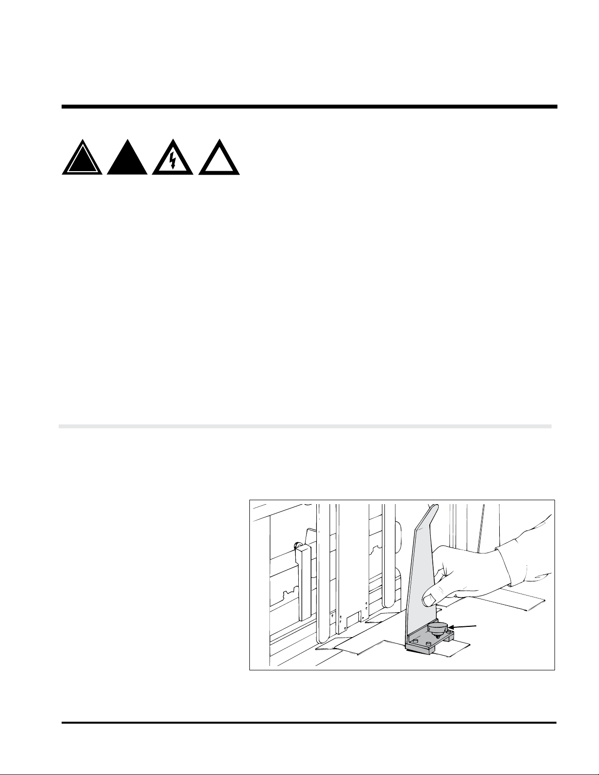
!
!
!
When performing initial installation, always
make sure you turn Off the main power
switch and disconnect all equipment from
the electrical power source. Failure to do so
can expose you to a potential start-up, and
therefore moving parts which can cause
serious injury.
Do not attempt feeder installation while the
inserter is running. Failure to do so can expose
you to moving parts which can cause serious
injury.
Avoid turning on the feeder or making initial
adjustments until all parts are secured. Failure
to do so can cause damage to equipment.
STEP 1:
Removing Rear
Guide Assembly
At the selected insert station, remove the fasteners that hold the
inserter rear guide assembly to the inserter back deck plate. Lift rear
guide assembly off of back deck plate (Figure 5).
Figure 5. Removing Guide Assembly Rear from Inserter
Rear guide
assembly

8Reliant 1500 Manual
STEP 2:
Removing T-Plate
With the rear guide assembly removed, you can now access the in-
serter T-plate. Simply lift off of back deck plate (Figure 6).
Figure 6. Removing T-Plate from Inserter
T-plate
STEP 3:
Repositioning
Separator Foot
• Locate the separator foot at the front side of the inserter station (at-
tached to top rotating shaft).
• With a screwdriver, loosen the inserter separator foot and tilt away
slightly from insert station assembly (opposite feeder) so the foot
does not interfere with material being fed (Figure 7).
• Retighten to secure.
Figure 7. Repositioning Separator Foot at Front of Inserter
Separator foot
9
Relaint 1500 Manual
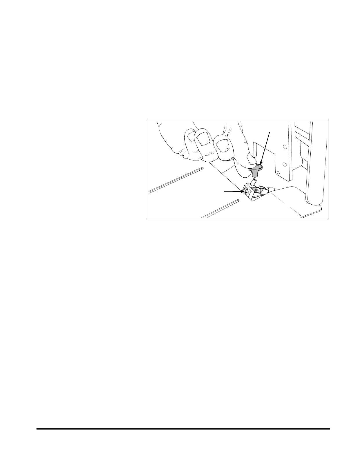
STEP 4:
Removing Suction
Cup and Closing Off
Vacuum Hose
• Locate the suction cup and hose from front side of insert station.
• Remove suction cup from vacuum assembly. See Figure 8.
• Lower and tilt the adjustable vacuum assembly forward (by turn-
ing the built-in thumbscrew). The vacuum assembly may be moved
down and to one side if it interferes with the material being fed.
• Close off the vacuum hose opening; any convenient plugging
method will do.
Figure 8. Removing Suction Cup from Vacuum Assembly
Suction cup
Vacuum assembly
10 Reliant 1500 Manual
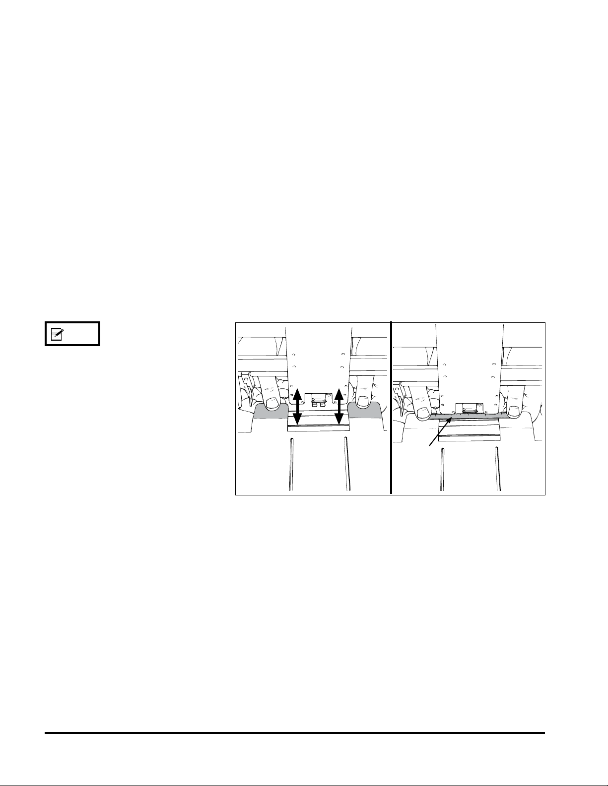
STEP 5:
Repositioning
Insert Guide Tabs
• Cycle the inserter until the gripper arm jaw is approximately 1/2 in.
(12.7 mm) from the hopper plate (leading edge of material exiting
feeder stops here).
• Locate the two insert guide tabs that protrude from under the back
deck plate. Bend these tabs as required (either up or down) until
their top surface is slightly above the bottom of the gripper arm
jaw. The material to be run will rest on these tabs. The bottom of
the gripper arm jaw must pass under the material without making
contact with it.
• As it is important that there be adequate clearance between the
guide tabs surface and the gripper jaw, use a at, thin rule (or
gauge) to test for clearance. Ideally, with the gripper jaw should be
fully open when testing.
• Center the gauge on the guide tabs and slide the gauge back and
forth on the tabs, making sure the gripper jaw does not touch the
bottom of the gauge. See Figure 9.
Figure 9. Respositioning Guide Tabs and Testing For Clearance
Inserco inserters only:
Remove the two insert guide tabs that protrude
from the back deck plate. Make a bend in each
tab approximately 1-3/8 in. (34.9 mm) from the
tip by placing the tab approximately 1-3/8 in.
(34.9 mm) into the rear guide assembly. Bend
the tab slightly and repeat same for second tab.
Reinstall insert guide tabs to back deck plate.
NO TE
Ruler or
gauge
11
Relaint 1500 Manual
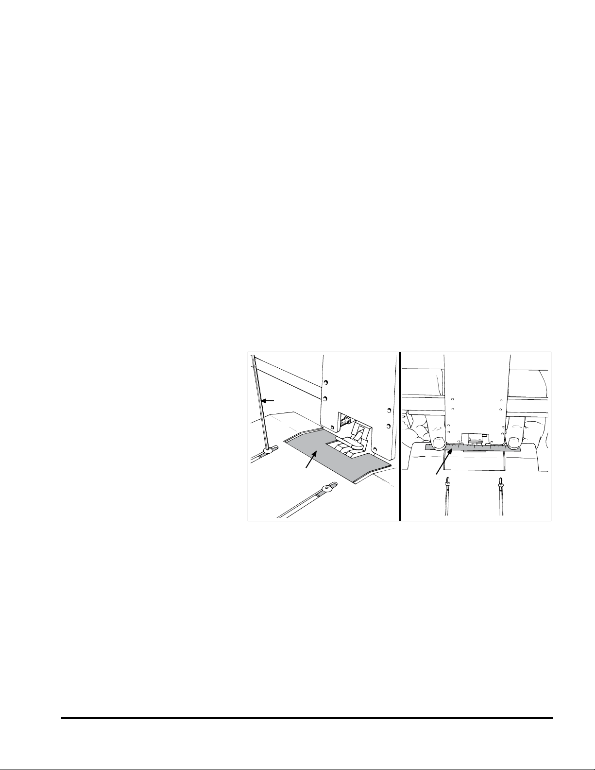
Optional Step:
Installing Insert
Plate Guide
When feeding materials less than 5 in. (12.7 cm) wide, you must in-
stall the provided insert plate guide with your machine. Install it from
the underside of the back deck plate using the two provided hex-head
screws; reuse the two slots previously used for mounting the rear
guide assembly.
• Start the screws from the top side of the back deck plate, leaving
them loose so you can move insert plate guide during placement.
• Position the insert plate guide so the top surface is slightly above
the bottom of the gripper arm jaw.
• Tighten to secure.
• As it is important that there be adequate clearance between the
guide tabs surface and the gripper jaw, use a at, thin rule (or
gauge) to test for clearance. Ideally, the gripper jaw should be fully
open when testing.
• Center the gauge on the guide tabs and slide the gauge back and
forth on the tabs, making sure the gripper jaw does not touch the
bottom of the gauge. See Figure 10.
Figure 10. Installing Optional Insert Plate Guide and
Checking for Clearance
Insert plate
guide
Allen
wrench
Ruler or
gauge

12 Reliant 1500 Manual
• Using the two provided hold-down spring assemblies (with support
bars), place each on the insert station rail (feeder side of inserter).
• Position each spring support bar so that they are equally spaced
from each edge of the material to be run.
• Tighten the built-in wing nut on each to secure.
• Check for placement and pressure of the hold-down spring as-
semblies by sliding a piece of material to be run under the springs.
There should be a “slight drag” when moving the material back and
forth.
• Make adjustments as required and recheck. See Figure 11.
STEP 6:
Installing Feeder
Hold-Down Spring
Assemblies
NO TE
Figure 11. Installing Hold-Down Spring Assemblies and
Testing for Drag
Feeder
hold-down
spring
Feeder
hold-down
springs
Use this conguration
for Bell & Howell
Mailstars, and 825
models.
Knowing how far from each edge of the material
to place the hold-down spring assemblies is a
combination of intuition and testing.
TIP
With material inserted between the springs and
the insert guide tabs, test the spring tension by
sliding the material back and forth. Tension
should not be so great that it distorts the material
as it moves.
If adjustment is required, loosen the hex-head
screw for each spring and move up or down on
support bar. Retighten when optimum tension is
achieved.
TIP
Certain inserter models require hold-down spring
assemblies to mount from the bottom side of the
cross-bar (see gure below). To invert, simply
remove screw and invert L-bracket and spring.

13
Relaint 1500 Manual
Figure 12. Aligning Feeder with Insert Station
STEP 7:
Aligning and
Securing Feeder to
Insert Station
• Using your nger, turn the drive belt to advance a piece of your
material through the gate assembly area and under the feeder hold
down springs.
• Continue advancing the material until the trailing edge of material
ts between the feeder exit rollers (.25 in. to .5 in., or 6.4 mm to
12.7 mm of material).
• Carefully slide the feeder into the inserter station and center the
leading edge of your material under the inserter hold-down springs.
Ensure the front edge of the material is in-line with the front hopper
plate. See Figure 12.
• Once you are satised with the feeder alignment, press down on the
feeder top plate to secure the feeder suction cups to the inserter rear
deck plate.
T-handle
screw
S uctio n
c up

14 Reliant 1500 Manual
STEP 8:
Initial Feeder Photo
Sensor Positioning
• With the machine turned Off, position the photo sensor by sighting
along the tubular barrel. It should point exactly at the leading edge
of material being held by the hold-down springs (Figure 13).
• Use the retractable extension to maneuver the photo sensor into
position for desired height and angle.
• During the nal adjustment of the photo sensor, you need to actu-
ally load material into hopper, turn the feeder Off, and cycle the
inserter. See Section 3, “Preparing for Operation”, for more infor-
mation.
NO TE
The nal photo sensor adjustment will align
slightly to the rear of the leading edge. This is
because when the photo sensor signals the feeder
to stop, the motor will over-travel slightly.
Figure 13. Initial Photo Sensor Adjustment
Photo
sensor
A perpendicular alignment to the material is
preferred. However, in many instances you may
be limited to an angular alignment due to the
constraints of the retractable extension and
cross-bar design.
IMPOR TANT
Table of contents
Other Barry-Wehmiller Wire Feeder manuals

Popular Wire Feeder manuals by other brands


Kemppi
Kemppi KEMPOWELD WIRE 200 Operation instructions

EWM
EWM Drive 4 Basic S D200 operating instructions

RNA
RNA STS 220-4 operating instructions

LOBSTER
LOBSTER ARF-800P instruction manual

Lincoln Electric
Lincoln Electric DX7 Instructions for use

Oerlikon
Oerlikon DMU P400 Instruction for operation and maintenance