Baxi 808 Instructions for use

5110831/04
INSTALLER AND OWNER GUIDE
This guide is intended to help you install and care for your Baxi Fires Division electric
heater. Please read carefully before installing and using your heater. However, if further
information is required, our Baxi Fires Division Technical Helpline
will be pleased to
help.
Telephone 08706 061 065 (National call rates apply in the United Kingdom)
In the Republic of Ireland call 0044 8706 061 065
Important: Please keep your guide in a safe place for future reference
Model 808
Electric Heater
© Baxi Heating U.K. Ltd.

Safety First.
Baxi Fires Division heaters are CE Approved and designed to meet the appropriate
British Standards and Safety Marks.
Quality and Excellence.
All Baxi Fires Division heaters are manufactured to the highest standards of quality and
excellence and are manufactured to ISO 9001.
CUSTOMER CARE
Thank you for choosing Baxi Fires Division
All Baxi Fires Division heaters are designed to meet the most stringent quality,
performance and safety requirements to provide our customers with many years of
trouble free service. This guide aims to improve your understanding and appreciation of
your new Baxi Fires Division heater, by providing simple and informative instructions
to enable you to install it and to ensure that you benefit from the excellent performance
and features it has to offer.
If you require further assistance, the Baxi Fires Division Technical Helpline will be
pleased to help.
Please telephone 08706 061 065
(local rates apply in the United Kingdom). In the
Republic of Ireland please telephone 0044 8706 061 065
FOR OTHER USEFUL TELEPHONE NUMBERS SEE THE LAST SECTION OF THIS
GUIDE
Baxi Fires Division, Erdington, Birmingham B24 9QP
www.firesandstoves.co.uk
Because our policy is one of constant development and improvement, details may vary slightly from those
given in this publication
Page 2
INSTALLER AND OWNER GUIDE

HANDLING AND UNPACKING
Before continuing any further with the installation of this heater please read the
following:
Important instructions.
!The lifting weight of the heater is as below:
Model Weight (kg)
Traditional 9kg.
Traditional with spacer 10.5kg.
Contemporary 11kg.
Contemporary with spacer 12.5kg.
!
One person should be sufficient to lift the heater. If for any reason this weight is
considered too heavy then obtain assistance.
!
When lifting always keep your back straight. Bend your legs and not your back.
!Avoid twisting at the waist. It is better to reposition your feet.
!
Avoid upper body / top heavy bending. Always bend from the knees rather than
the waist. Do not lean forward or sideways whilst handling the heater.
!
Always grip with the palm of the hand. Do not use the tips of fingers for support.
!
Always keep the heater as close to the body as possible. This will minimise the
cantilever action.
!Use gloves to provide additional grip.
!Always use assistance if required.
!Remove the spare bulb from the top polystyrene fitment.
Page 3
INSTALLER AND OWNER GUIDE

SAFETY
Always
! Always install the heater in accordance with this guide. If in doubt obtain
expert advice.
! Always make sure the electrical socket is accessible and located adjacent to, but
not above the heater.
! Always disconnect the heater from the electrical supply before carrying out
cleaning, maintenance or replacing the light bulbs.
! Always
make sure the heater is firmly secured to prevent it from being tipped over.
! Always use a fireguard when young children and infirm persons can come into
contact with the heater.
! Always use genuine Baxi Fires Division spares.
Never
! Never leave children unsupervised in a room where the heater is ON and
unguarded.
! Never obstruct or cover the fan outlet or force items into heater openings.
! Never install or use the heater anywhere where water is in use, i.e.
Bathrooms, Kitchens, Shower Rooms, Swimming Pools etc.
! Never use aerosols or steam cleaners on or around the heater.
! Never route the mains supply cable under carpet etc.
! Never install the heater close to curtains or combustible materials.
! Never use the heater to dry clothes etc.
! Never sit or stand on the heater.
FITTING THE HEATER
The installation of this heater requires a reasonable level of DIY skills.
Please read this guide thoroughly before commencing installation and if in doubt,
seek help from a competent person
Do I need any tools?
1.
Depending on which style of fascia you have (traditional / contemporary) you will
need the below screwdrivers: -
1 off Pozidrive / Phillips / cross head screwdriver. This is required on traditional
models. This should have a number 2 size end. If you are unsure about the size of the
Page 4
INSTALLER AND OWNER GUIDE

end simply make sure that the end fits into the screws that secure the fascia to the
heater. If the end is too small then the end will spin and damage the screw.
1 off Flat end
screwdriver. This is required on both models. The end should fit into the
slot head screws supplied with the heater.
2.
For drilling into brickwork you will need an electric drill (preferably with hammer
action) and appropriate size drill bit for the wallplugs supplied (See figure 3).
Where can I fit the heater?
This heater can be fitted into fireplaces or surrounds where the following dimensions
are available.
Width 390mm - 450 mm (15.35 inches - 17.72 inches)
Height 555mm - 590 mm (21.9 inches - 23.2 inches)
Depth At least 75mm (At least 3 inches)
There should be at least 30mm (1.2 inches) clearance between the top of the fascia and
anything such as a shelf, fireplace surround or mantel etc. This will allow the fascia to
be lifted off or removed during servicing. To check this gently place the fascia against
the surface to which it is to be fixed. Measure the distance from the top of the fascia.
The heater is of a slim design and should suit most fireplace openings and fire
surrounds. However, there may be some applications that require the need for a spacer
where a fireplace opening or fireplace surround opening are not available i.e. a flat wall.
Some models are not supplied with a spacer frame kit. This optional spacer frame kit is
obtainable either from the your heater supplier or direct from Baxi Fires Division Sales.
The kit is:
!
Models with traditional fascia - 75mm (3 inch) spacer kit (Kit number 05801T1).
Important Electrical Safety
The heater must not
be located in front of or under an electrical socket, the socket must
always be accessible in order to disconnect the heater from the electrical supply for
maintenance and cleaning.
Important! This heater must be earthed.
!
The heater is supplied with a 3 pin 13 Amp fused re-wireable plug with 1mm² 3 core
cable.
! The wires in the cable are coloured in accordance with the following code: -
Live =Brown Neutral = Blue Earth = Green /Yellow
! The mains supply must be safely routed from the heater to an electrical socket.
Page 5
INSTALLER AND OWNER GUIDE

Moving the Cable Guide
At the base of the heater you will find the electric
cable which runs through a rectangular plastic cable
guide. The cable guide is fitted into the rectangular
slot on the right side of the heater. If required this
can be moved and put in the rectangular slot in the
centre or left hand side of the heater. For removal
and fitting please see below.
Removing the cable guide
1. Before moving the cable guide please note that the
lip of the cable guide is on the outer edge of the base
(See figure 1- Item 1).
2. To remove the cable guide push and lift the tab on
the bottom of it and the cable guide will open (See
figure 1- Item 2).
3. Lift the electric cable clear of the cable guide.
4. Hold the bottom of the cable guide close to the
heater then gently pull the cable guide away from
the rectangular slot (See figure 1- Item 3).
Fitting the cable guide.
When fitting the cable guide please remember that
the lip of the cable guide
has to be fitted against the
outer face of the base (See
figure 1- Item 1).
1. Gently pinch the sides of
the cable guide (See figure
1 - Item 4) and push into
the desired rectangular slot.
2. Place the electrical cable
into the guide and close the
top.
If the mains cable is
damaged, to avoid a hazard
it must be replaced by a
Baxi fires division
authorised service agent, or
Page 6
INSTALLER AND OWNER GUIDE
Figure 2. Removing the
fascia.
Figure 1. Removing and
positioning the cable guide.
Item 1
Item 2
Item 4
Item 3

similarly qualified person (See the last page of this guide for useful telephone numbers).
All external wiring between the heater and the electrical supply shall comply with
current IEE regulations.
Removing the fascia on models fitted with a traditional fascia.
1. Remove the two fascia securing screws (See figure 2). Remove the front fascia by
gently pulling the base of the fascia forward whilst lifting clear of the support brackets
at the top of the heater (See figure 2).
2. Keep the fascia in a safe place while installing the heater.
Heater Fixing
All of the fixings supplied with the heater have been identified as in figure 3.
The heater must be fixed into position to prevent it from being tipped over
The following fixing options are available:
Screw Fixing
Wire Fixing
Spacer Frame (
The spacer frame may not be supplied with the heater - see details
in section headed ‘Where can I fit the heater?’).
If fitting the heater into a fireplace or surround opening, try the heater in the opening to
ensure that it will fit.
If fitting the heater onto a decorative hearth surface such as marble or tile it is advisable
to protect the hearth surface. Do not drag the heater across the surface of the hearth as
this may scratch the hearth surface.
Page 7
INSTALLER AND OWNER GUIDE
Figure 3. Loose parts identification

Method A - Screw fixing
Note - If fixing to marble it is recommended that
Method B - ‘Wire fixing’ is used. Drilling marble
without the correct tools and experience may result in
the marble cracking.
1. Place the heater into the fireplace or surround
opening. Make sure that the heater is in the middle of
the surround or fireplace.
2. There are two slotted holes in the top of the heater
(See figure 4). Mark through the slotted holes so that
their position is clear when the heater is removed.
3. Remove the heater
4. Drill an appropriate size hole in each of the marked
positions. Insert wall plugs into the drilled holes.
5. Place the heater so that the slotted holes are in line with the wallplugs in the fixing
surface.
6. Screw and secure the heater with two woodscrews screws (See figure 3).
Method B - Wire Fix
This method of fixing needs a fireplace opening and is recommended when fixing the
heater to a marble surround or where the wall or brickwork is in poor condition.
1. The fixing kit supplied with the heater
includes a steel wire and eyescrew (See
figure 3). These can be used to secure the
heater to the back of a fireplace opening.
2. Mark the eyescrew position on the centre
line at the back of the fireplace opening and
at a height of 533-560mm (21 inches - 22
inches) (See figure 5).
3. Drill an appropriate size hole in the
marked position.
4. Insert a wallplug into the drilled hole.
5. Screw the eyescrew into the wallplug.
6. Position the heater in front of the
fireplace opening.
7. At the top of the heater there are four
small holes, two each side of the heater
(See figure 6- Item 1). From the front of the heater, thread about 50mm (2 inches) of the
steel wire into the inside small hole on the left side of the heater (See figure 6 - item 2).
Page 8
INSTALLER AND OWNER GUIDE
Figure 5. Eyescrew position.
Figure 4. Slots for screw
fixing.

8. Thread the other end of the wire
through the remaining small hole on the
left hand side of the heater. Continue to
push the wire through this hole until there
is only a small loop of wire at the front of
the heater (See figure 6 - item 3).
9. At the back of the heater there will be a
long piece and a short piece of wire
coming through the two holes. Hold the
short piece and give the long piece a
gentle tug. This will secure the steel wire.
Take the long piece and thread this
through the eyescrew in the back of the
fireplace opening (See figure 6 - item 4).
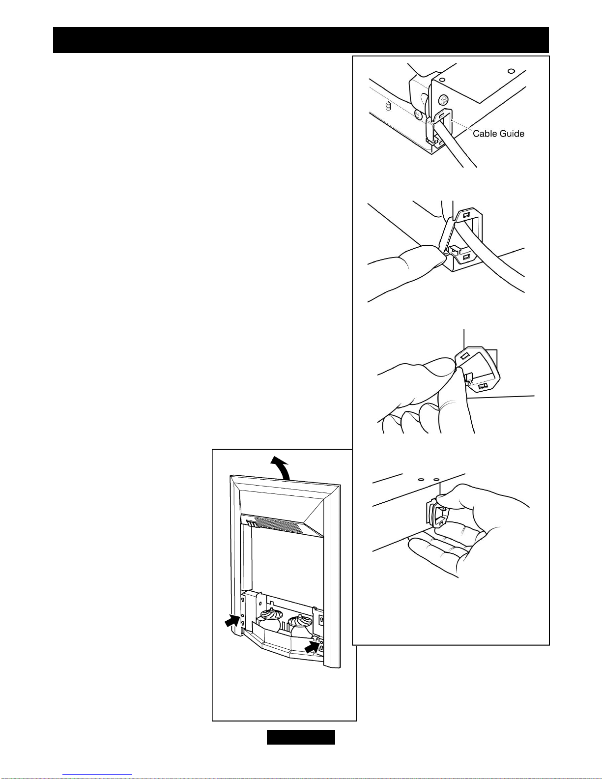
10. From the back of the heater thread the
long piece of steel wire through the outer
small hole on the right hand side of the
heater (See figure 6 - item 5).
11. Locate the heater in the fireplace
opening, then from the front of the heater,
gently pull the steel wire on the right hand
side to gather up the excess until the
heater is secure. Thread the wire through
the remaining small hole to lock the wire
and heater in place (See figure 6 - item 6).
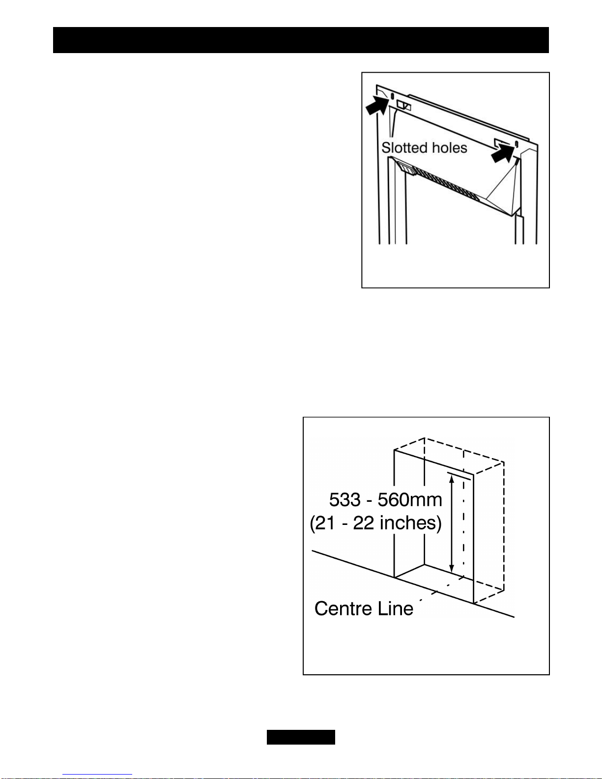
Method C - Spacer Frame
The spacer frame is for use during installations
where a chimney recess or rebated fire surround
are not available. For your safety the frame and
heater must be securely fixed to the rear wall.
1. Fit the four self adhesive rubber pads to the rear
of the spacer frame. They should be located on the
rear of the vertical legs as in figure 7.
2. Position the spacer frame against the wall.
Ensure that the spacer frame is central to the
fireplace.
3. The top rear flange of the spacer frame has two
screw locations. Mark the positions of the two screw locations on the rear wall (See
figure 8).
Page 9
INSTALLER AND OWNER GUIDE
Figure 7. Rubber pad locations
Figure 6. Steel wire fixing (The fuel effect
may differ from that shown)

4. Remove the spacer frame from the fireplace
and place away from the work area.
5. Drill the screw locations using a no. 12
masonry drill bit.
6. Insert the two wall plugs provided into the
holes
7. Insert a screw into each hole and screw in until
there is approximately 6mm of screw protruding
from the wall.
Preparing the heater for installation.
1. Using the four screws provided, fix the heater
to the spacer frame.
2. There is a supply cable slot on both sides of
the spacer frame. It is located at the base. Decide
which side to pass the supply cable through. The
nylon grommet supplied has a slot along its
length. Fit the grommet to the mains cable with
the flange edge positioned away from the fire
(See figure 9).
4. Position the supply cable in the spacer frame
slot
5. Slide the nylon grommet along the supply cable towards the heater. When the
grommet reaches the slot, push it into the slot up to its flange (See figure 9).
Fitting the heater.
1.
Locate the spacer frame and heater over the screw heads ensuring a tight fit. If the fit
is loose, remove the spacer frame and heater from the wall. Tighten the wall screws
slightly and reposition the spacer frame and heater.
Fitting the fascia on Traditional models.
1. Hook the brackets on the rear of the main fascia
over the brackets on the heater (See figure 10).
2. Secure with the two screws removed previously
(See figure 2)
3. Locate the lower firefront casting onto the
fascia. The two screws on the rear of the firefront
casting locate into the two keyhole slots in the
fascia
4. Place the loose coals onto the fuel support (a
Page 10
INSTALLER AND OWNER GUIDE
Figure 9. Fitting the grommet
Figure 8. Bracket positions
Figure 10. Fitting the facia.

glove is provided with the coal pack). It is not
necessary to use all the coal supplied. If the
coal pieces are too large then a suitable tool
can be used to break them.
Important Note:
The coals are for decorative purposes
only. There is a choke risk to young
children. Make sure they cannot gain
access to them.
Fitting the fascia on Contemporary
models.
The contemporary fascia consists of three
parts. Two sides and a top. These are held in
place with six magnets. Fit the firefront
assembly before the fascia. To do this align
the four holes in the firefront assembly with those
on the heater. Secure with the four screws
supplied.
1. Lay the three fascia parts face down on a flat
surface as in figure 11. Each side trim has a small
tab at the top. Position the tab to the outside upper
edge (See figure 11).
2. Locate the tabs into the fold on the top edge of
the top trim.
3. Locate the six magnets on the side trims as in
figure 12. Note that bottom edge of the the upper
magnets are in line with the bottom of the top
trim.
Page 11
INSTALLER AND OWNER GUIDE
Figure 12.
Figure 11.

4. Lift the trims at the top outer edges. This will
keep the trims together. Locate the trims to the
heater as in figure 13.
5. Place the loose pebbles on top of the fuel
support. It is not necessary to use all the pebbles
supplied.
Important Note:
The pebbles are for decorative purposes
only. There is a choke risk to young children.
Make sure they cannot gain access to them.
USING THE HEATER
Important Safety
Never cover the heater or obstruct the openings at the base of the heater, this could
cause overheating and consequent risk of fire.
What are the three switches for?
The heater is operated by three switches located below the hood on the left hand side of
the heater.
Switch 1 =
Main On - Off. (In the ‘ON’ position, only the flame
effect operates)
Switch 2 =
1kW fan heat setting and flame effect. (Switch 1
needs to be in the ‘ON’ position to enable switch 2
to operate).
Switch 3 =
2kW fan heat setting and flame effect. (Switch 2
needs to be in the ‘ON’ position to enable switch 3
to operate).
Page 12
INSTALLER AND OWNER GUIDE
Figure 13. (The fuel effect may
differ from that shown)

CLEANING AND MAINTAINING THE HEATER
How do I Clean my heater?
The heater fascia, spacer frame and glass parts need only to be wiped clean with a dry
soft cloth, do not use polishes or abrasive materials. Heaters with contemporary fascia
may have finger prints on the fascia surface. These can be removed by applying a small
amount of ‘baby oil’ to a lint free non-abrasive cloth and wiping the surface. Use a
clean cloth to remove the oil.
I have a problem with my heater!
Important Safety
Before undertaking maintenance or replacing the light bulb(s) always disconnect
the heater from the electricity supply by removing the 3 pin plug and allowing the
heater to cool.
1. My heater is on but there is no light / low light.
This is possibly a light bulb failure. Remove the light bulb as below and check it in a
table lamp that is known to work. If it does not work in the table lamp then replace it as
below.
The light bulb fitted to this heater is a 60Watt fireflame (Red) Edison screw type, but
due to the indeterminate life span and ease of replacement, it is specifically excluded
from the guarantee.
To replace the light bulb(s).
1. To gain access to the light bulb(s), remove the loose coals / pebbles from the fuel
support and place them onto an old newspaper or plastic bag. This will prevent them
from marking the surface.
2. On Traditional models remove the firefront casting.
3. Remove the fascia in the reverse order to that shown on pages 9-11.
4. On Contemporary models unscrew and remove the firefront assembly.
6. Unscrew the bulb(s) in a clockwise direction.
7. Replace the light bulb with a 60Watt fireflame (Red) Edison screw type bulb.
8.On Contemporary models it the firefront assembly back into place using the four
screws previously removed.
9. Fit the fascia (See pages 9-11).
10. On Traditional models fit the lower firefront casting and ash pan.
11. Place the coals / pebbles back on top of the fuel support.
2. My heater is on but there is no light or heat.
The first thing to do is check the wall socket. To do this plug in a known working
appliance. If the appliance you have plugged in works then there is a good chance that
Page 13
INSTALLER AND OWNER GUIDE

the problem lies with the 13Amp fuse in the heater plug. If either fuse or socket is
suspected, have them checked by an electrician.
3. My heater is on but there is no heat.
A cut out device is fitted to the heater to prevent damage due to over heating. If it
operates due to an obstruction in the airflow, the heater must be turned off and allowed
to cool for 15 minutes and the obstruction removed before restarting.
4. I Have a problem that is different to those in the previous examples 1- 3.
Below is a list of Useful Telephone numbers
For general advice about your heater:
BAXI FIRES DIVISION TECHNICAL HELPLINE 08706 061 065.
To report faults or arrange for your heater to be serviced:
BAXI FIRES DIVISION SERVICE 08706 090 081.
For sales or product information:
BAXI FIRES DIVISION SALES 08706 061 067.
CALLERS IN THE REPUBLIC OF IRELAND
Call 0044 8706 061 065
For spares inquiries
Spare parts are available nationwide via the ‘interpart stockist network’. For your
local stockist consult Yellow pages under ‘Central Heating’.
When ordering spare parts please have the below information available. This will help
us to deal with your call quicker and avoid you having to make a second call.
! Your Post Code
! Type of Heater (Electric or gas)
! Model, Name and serial number (This information can be found on a small label
attached to the inside lower left of the heater. To see this you will have to remove the
lower firefront / casting and ash pan.
! The fault, problem or request.
What should I do when I’m ready to dispose of my heater?
The plug should be removed from the mains cable and the mains cable cut from the
heater. These should be disposed of with the heater.
Environmental Protection.
Waste electrical products should not be disposed of with household waste.
Please recycle where facilities exist. Check with your local authority or retailer
for recycling advice.
Page 14
INSTALLER AND OWNER GUIDE
Other manuals for 808
1
Table of contents
Other Baxi Electric Heater manuals
Popular Electric Heater manuals by other brands

Sawotec
Sawotec SAVONIA manual

Dimplex
Dimplex XLS12N operating instructions

HeatQ
HeatQ HEC 1.0 Assembly instruction

SHUODU ELECTRIC
SHUODU ELECTRIC NSB-120SL8 instructions

American Standard
American Standard Foundation BAYHTFA305 Series installation instructions

Ecostrad
Ecostrad iQ Plus Series instruction manual

Holmes
Holmes AccuTemp HFH595-CN owner's guide

DeLonghi
DeLonghi HSX4315ECA Instructions for use

DeLonghi
DeLonghi HSX3315FTS-6A Instructions for use

Sentiotec
Sentiotec 136E Instructions for installation and use

Grandhall
Grandhall THD1500EU Installation, operation & maintenance manual

NuTone
NuTone 665RP instruction manual