7
1Rinse the pipeline thoroughly.
2Close the shut-o valves in the inlet and outlet.
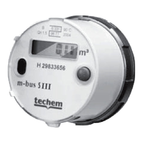
3Unscrew the temporary cover or old meter anti-clockwise.
4Clean the connector's sealing surfaces and the measuring capsule's O-ring.
5Grease the connector's sealing surfaces lightly with tap grease.
6Screw the measuring capsule hand-tight into the connector and tighten it by 1/8to
max. 1/4turn with the Techem hook spanner.
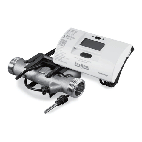
7Turn the computer unit to a position in which it is easily readable.
Installing the temperature sensors
Î 1
1Remove the pressure from the sensor installation location.
2Unscrew the closing screw from the special ball valve.
3Place the enclosed O-ring on the assembly pin. Only use one O-ring.
When replacing sensors, replace the old O-ring with a new one.
4Using the assembly pin, turn the O-Ring into the bore hole of the closing screw with a
rotating movement.
5Place the O-ring in its final position using the other end of the assembly pin.
6Place the assembly pin with the sleeve end over the temperature sensor as far as it
will go.
7Clasp the temperature sensor with both halves of the plastic screw directly over the
assembly pin. Press both halves together so that both pins from one half fit in the bore
holes in the other half of the plastic screw.
8Place the temperature sensor with the plastic screw in the bore hole of the closing
screw and tighten it hand-tigh. Do not use any tools for this!
Functional check
1Open the shut-o valves in the inlet and outlet.
2Check the leak tightness of the union piece connector.
3Press the push-button on the meter to switch on the display.
Final tasks
1Apply seals to the union piece connector and both temperature sensor closing covers.
2Mark the connector visibly with the label enclosed.
3Reconnect the insulation correctly.
M-bus / impulse cable connector
1Remove the closing cover from the casing.
2Plug the M-bus / impulse cable plug into the existing opening.
3For the M-bus version, only the outer pins are occupied. Polarity can be set as desired
here.
4For the pulse output version, pay attention to correct polarity: Insert volume output
(green) under the inscription V, energy output (white) under the inscription E.
5Close the closing cover.
6Seal the closing cover dust and grease-free.
7Lay the cable to the branching socket with cable plug clamps, shorten it to the re-
quired length and equip the wires with wire sleeves.
GB


