BEAMEX TC305 User manual
Service manual for
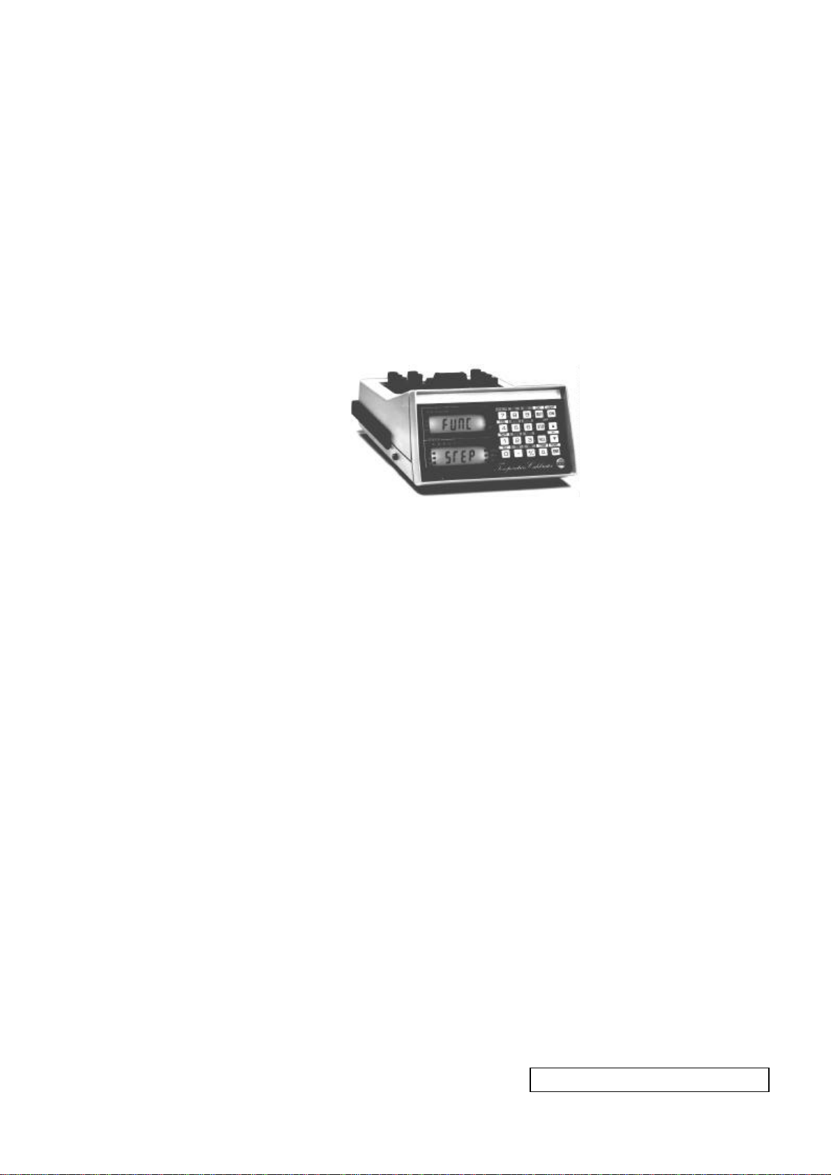
TEMPERATURE CALIBRATOR
TC305/TC303
Dear user,
We have made every effort to ensure the accuracy of the
contents of this manual. Should any errors be detected, we
would greatly appreciate to receive suggestions to improve the
quality of the contents of this manual.
The above not withstanding, we can assume no responsibility
for any errors in this manual or their eventual consequences.
We reserve rights to make modifications to this manual without
any further notice.
For more detailed technical data about the Service manual for
TC305/TC303, please contact the manufacturer.
© Copyright 1997
OY BEAMEX AB
P.O. Box 5
68601 Pietarsaari
FINLAND
Tel +358 - 6 - 7840111
Fax +358 - 6 - 7840404
E-mail: [email protected]
Internet: http://www.beamex.com
8830100 / SETC305 / 912417

CONTENTS
PART A. FUNCTIONAL DESCRIPTION
1 GENERAL ................................................................................................................................A - 1
2 SECTION A..............................................................................................................................A - 2
3 SECTION B..............................................................................................................................A - 3
PART B. SERVICE
1 WARNING DURING OPERATION......................................................................................... B - 1
2 HARDWARE ERROR MESSAGES ....................................................................................... B - 2
3 SERVICE, TROUBLESHOOTING AND REPAIR.................................................................. B - 4
3.1 Disassembling and reassembling the calibrator......................................................... B - 4
3.2 Updating the software version....................................................................................... B - 5
3.3 Installing software options............................................................................................. B - 5
3.4 Replacing the battery pack............................................................................................. B - 6
3.5 Hardware troubleshooting.............................................................................................. B - 6
3.5.1 Front assembly.............................................................................................................B - 7
3.5.1.1 Display and keypad board......................................................................................B - 7
3.5.1.2 Battery pack............................................................................................................B - 7
3.5.1.3 Power supply board................................................................................................B - 8
3.5.2 Analog i/o assembly .....................................................................................................B - 9
3.5.3 Processor boards .......................................................................................................B - 10
3.5.4 Optional 24V supply board.........................................................................................B - 10
PART C. CALIBRATION
1 GENERAL ............................................................................................................................... C - 1
2 EQUIPMENT REQUIRED FOR CALIBRATION.................................................................... C - 1
3 PREPARATIONS BEFORE CALIBRATION.......................................................................... C - 3
4 SECTION B MEASUREMENTS............................................................................................. C - 4
5 SECTION A MEASUREMENTS............................................................................................. C - 6
6 RESISTANCE SIMULATION.................................................................................................. C - 8
7 INTERNAL REFERENCE JUNCTION COMPENSATION.................................................. C - 10
7.1 Calibration with thermocouple..................................................................................... C - 11
7.2 Calibration with a thermometer ................................................................................... C - 12

8 CALIBRATION DATE........................................................................................................... C - 13
9 AUTO CALIBRATION OF GENERATION RANGES........................................................... C - 14
10 CALIBRATION PERIOD..................................................................................................... C - 15
PART D. SERIAL COMMUNICATION
1 GENERAL ............................................................................................................................... D - 1
2 TECHNICAL SPECIFICATIONS ............................................................................................ D - 2
2.1 Flow control (XON/XOFF)............................................................................................... D - 2
2.2 Checksum......................................................................................................................... D - 2
2.3 Acknowledgment (ACK/NAK) ........................................................................................ D - 3
2.4 Line terminators (CR/LF)................................................................................................ D - 3
3 COMMANDS........................................................................................................................... D - 4
3.1 Interface configuration and control............................................................................... D - 5
3.1.1 Communication control................................................................................................ D - 5
3.1.2 Line termination........................................................................................................... D - 5
3.1.3 Control of sent measurement/generation readings..................................................... D - 6
3.1.4 Use of status codes..................................................................................................... D - 6
3.1.5 Formatting of readings................................................................................................. D - 7
3.2 Device configuration....................................................................................................... D - 8
3.2.1 A-section (upper display) electrical unit selection....................................................... D - 8
3.2.2 A-section temperature / electrical mode selection...................................................... D - 8
3.2.3 Temperature sensor selection..................................................................................... D - 9
3.2.4 Temperature scale....................................................................................................... D - 9
3.2.5 CJ-selection............................................................................................................... D - 10
3.2.6 Generation value setting ........................................................................................... D - 10
3.2.7 Emulation of mechanical switch settings .................................................................. D - 10
3.2.8 B-section (lower display) electrical unit selection ..................................................... D - 11
3.2.9 Local on/off................................................................................................................ D - 11
3.3 Calibration and service................................................................................................. D - 12
3.4 Commands for key emulation / inquiry....................................................................... D - 13
3.5 Other standard commands........................................................................................... D - 14
3.5.1 System details ........................................................................................................... D - 14
3.5.2 Set/get date ............................................................................................................... D - 14
3.5.3 Display message....................................................................................................... D - 15
3.6 Special commands........................................................................................................ D - 16
APPENDIXES
APPENDIX A: STATUS CODE / ERROR MESSAGES IN SERIAL COMMUNICATION .......X - 1
APPENDIX B: MEASUREMENT PRINTOUT FORMAT ...........................................................X - 2
APPENDIX C: ALGORITHMS....................................................................................................X - 4
APPENDIX D: PC106P RS-232 SAVEABLE OPTIONS..........................................................X - 4

FUNCTIONAL
DESCRIPTION

TC305/TC303 - Functional Description A- 1
1 GENERAL
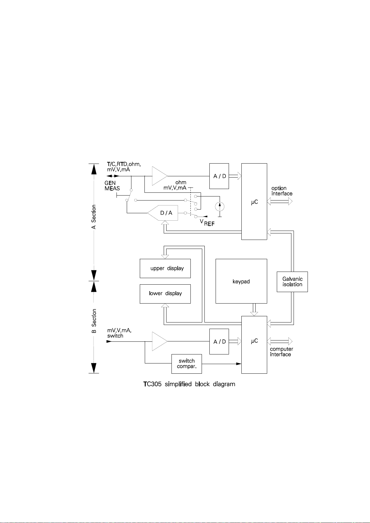
The functions of TC305/TC303 temperature calibrator are divided in two sections.
The left side of the connection panel and the upper display constitute the
Measure/Generate section which is called the A-section. The right side of the
connection panel and the lower display constitute the Measure section, called
here the B-section.
A- 2TC305/TC303 - Functional Description
2 SECTION A
The A-section microprocessor takes care of electrical measurements and
generations/simulations. It also makes all calculations required for temperature
sensor simulations and measurements. It uses one A/D-converter for all these
measurements and one D/A-converter for generations/simulations.
In resistance measurement TC305/TC303 generates the measurement current
and measures the voltage across the resistance. It switches off the current for a
part of the time. This enables compensation of the thermovoltages in the
resistance measurement circuit.
In voltage and current generation TC305/TC303 makes the output with the D/A-
converter and assures the accuracy by continuously measuring the generated
value.
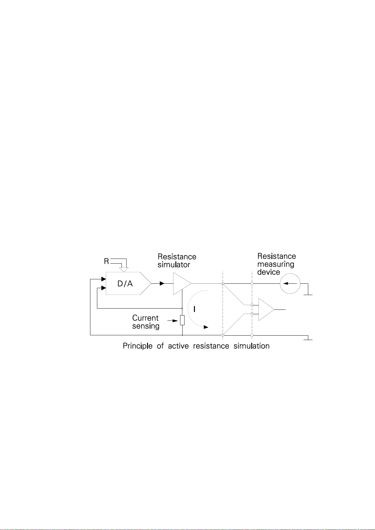
In resistance simulation there should be an external resistance measurement
device measuring the resistance between the TC305/TC303 output terminals.
The D/A-converter detects the measurement current coming from the external
measurement device. It controls the voltage across the resistance output
terminals so that it is in the correct ratio to the detected current. The
microprocessor defines this ratio according to the Ohm's law and the simulated
resistance value.
Theoretically the resistance simulation could be able to simulate the given
resistance also to an AC circuit. In practice, anyhow, it is always too slow to
achieve reasonable accuracy, if the measurement device uses AC supply for
resistance measurement. Fortunately AC measurement of resistance is very
seldom used nowadays.
Some resistance measurement devices - like TC305/TC303 itself - use pulsed
current for resistance measurement. Simulation to these devices is possible with
TC305/TC303. The measurement device should, however, give enough time for
the circuits to settle after switching the current on. This is normally necessary also
because of the inductance and capacitance of the industrial resistance
measurement circuits.

TC305/TC303 - Functional Description A- 3
3 SECTION B
The B-section microprocessor uses another A/D-converter to measure current or
voltage. There are also circuits for switch state detection. There is a galvanic
isolation between the two sections. This enables you to generate the input of an
instrument and simultaneously measure the instrument output.
The B-section microprocessor also carries out the communication with the user
and with the computer via the serial computer interface.

SERVICE

TC305/TC303 - Service B- 1
1 WARNING DURING OPERATION
If you try to use TC305/TC303 in a strange way, it may warn you about it. The
following list explains the used warning messages in detail.
NO TCAL Attempt to start Quick Store or Quick Examine function
when TCAL305 expansion software is not installed.
NO ID No instrument identifier defined.
CLEAR AREA No instrument data in the loaded memory area.
UNDEFD SENSOR Attempt to load instrument data from Data Memory. The
defined sensor type was not known and loading was denied.
If a special sensor is included in the instrument data and the
special sensor is no longer fixed to the defined special
sensor place, the required special sensor arrow is lit.
CONFIG ERROR Attempt to start the Quick Store function with faulty
configuration, e.g. the instrument type is FREE.
SCAN ERROR The actuation or deactuation point of a limit switch out of the
scan limits or scan limits out of the generation/simulation
range of the calibrator.
NOT SAVED Attempt to change the contents of the Working Memory
without saving the results of the latest Quick Store to the
Data Memory.
CANCEL STORE Escaping from Quick Store before altering the contents of
the Working Memory.
DATA LOST TC305/TC303 has lost its configuration data, instrument
data and calibration results due to the missing RAM backup
voltage. The obvious reason is, that the battery has been
disconnected for a while or empty battery has not been
recharged in time. Switch the calibrator off and check the
battery wiring, recharge the battery or replace it if necessary.
If the error remains, send TC305/TC303 to Beamex or
representative for repair.

B- 2TC305/TC303 - Service
DATE LOST TC305/TC303 calendar/clock has lost the date and time due
to the missing backup voltage. The obvious reason is, that
the battery has been disconnected for a while or empty
battery has not been recharged in time. Check the battery
wiring, recharge the battery or replace it if necessary. Enter
the new date and time as explained in part C of this manual.
If the error remains, send TC305/TC303 to Beamex or
representative for repair.
CALIBR SOON According to the given calibration period, you should soon
recalibrate the TC305/TC303 calibrator.
NO CAL DATA This message is used in new devices before the initial
definition and calibration. It should not come in sold devices.
However, if it comes, there is fault in the EEPROM memory.
TC305/TC303 has lost all calibration data. Do not use it for
calibration purposes. Send it to the manufacturer for repair.
NO DATA Attempt to use the Quick Examine function when the
Working Memory is empty.
NO FREQ MODULE The instrument to be calibrated requires a frequency module
or the settings of the frequency module does not correspond
to the requirements. The inverted arrows in TC305/TC303
display the settings needed for the operation. This applies
for software versions 1.31 and later. In earlier software
versions the message was "BAD FRQ UNIT x".

TC305/TC303 - Service B- 3
2 HARDWARE ERROR MESSAGES
If TC305/TC303 detects errors in its internal functions, it denies all operations and
shows an error code:
ERROR
CODE n
The error code helps to decide, how to correct the error.
Error codes:
1The A-section microprocessor doesn't answer when called from the
B-section.
2Fault in the B-section analog part.
3Checksum error in EEPROM memory.
4Fault in the A-section analog part.
5Error in the A-section digital part.
6Error in the clock/calendar circuit.
7The watchdog circuit detected fault in operation during previous use.
8Errors in communication between A- and B-sections.
9Software option data in EEPROM corrupted.
10 According to A/D-converter readings, the A-section analog part is faulty.
The messages give some idea, where the error might be. You can't, however,
make any absolutely sure conclusions of them. Error codes 2,3,4,9 and 10
normally show that the error is in the analog i/o assembly. Error codes 6 and 7
mean that the main processor board is faulty. Obvious cause for the error code 5
is on the temperature processor board. Errors 1 and 8 may be caused by a fault
on either one of the two processor boards. In all cases the actual fault can be in
cabling between the boards. In some cases the fault is said to be in the analog i/o
assembly but it actually is on one of the processor boards or vice versa. Fault on
the power supply board can cause practically any malfunction or error message.

B- 4TC305/TC303 - Service
3 SERVICE, TROUBLESHOOTING AND REPAIR
If you can't switch the calibrator on at all, the most obvious fault is empty battery.
If charging doesn't help, check the battery voltage from the battery terminals. If
the battery is ok, but you still can't start the calibrator, the fault is obviously in
internal cabling or on the main processor board. If your device stops and shows
an error code, write down the shown code number and switch the calibrator off.
Wait five seconds and switch the calibrator on to see, if the error remains. If the
error remains or repeats later, see the following chapters for more help. Only
board level service is explained. Component level trouble shooting would require
detailed knowledge both of the hardware and of the software.
If the fault is obvious or if you can locate it using the information given in this
manual, you can perhaps repair it locally. Otherwise, send the device to the
manufacturer or to the representative for repair. In case of warranty repair, always
send the device to us or to our representative. Most representatives can carry out
board level trouble shooting and replace faulty boards or units.
3.1 Disassembling and reassembling the calibrator
The calibrator must be taken apart in case of software update, read/write memory
installation, battery replacement or hardware trouble shooting. The following steps
are required to disassemble TC305/TC303:
∗ Switch off the calibrator.
∗ Loosen the four screws on the bottom of the calibrator.
∗ Carefully lift the rear of the cover and remove the cover.
∗ Remove the handle and the handle springs.
∗ Remove the two screws holding the front assembly.
∗ Loosen the front assembly cable connectors from the processor boards
below it and from the analog i/o assembly.
∗ Remove the four screws on the front and rear of the analog i/o assembly.
∗ Lift the analog i/o assembly and loosen its cable connectors from the
processor boards.
Reassembling requires opposite steps. If the front assembly has been removed,
TC305/TC303 looses date, time and all data stored in the read/write memory.
This includes Working Memory, Data Memory and all configuration settings.
Calibration data as well as installation of software options do not change,
because they are stored in the non-volatile EEPROM memory. Setting of date,
time and all configurations is explained in part C of the instruction manual. After
disassembly, TC305/TC303 may show error message 'ERROR CODE 7'. If this
happens, switch the unit off for 5 seconds and try to switch on again.
Note:
When disassembling a TC305/TC303, all special sensor definitions will be

TC305/TC303 - Service B- 5
lost. After reassembling, refer to chapter "Special sensor definition" in
part C of the Instruction manual to fix your additional sensor to a special
sensor number.
3.2 Updating the software version
TC305/TC303 software is stored in two EPROM memories, one on each
processor board on the bottom of the calibrator. The left side (front view)
processor board is named 'main processor board' and the right side processor
board is 'temperature processor board'. The EPROMs are labeled 'Main
Processor' and 'Temp. Processor' respectively. To install a new software version,
follow the updating instructions delivered with the new EPROM(s).
3.3 Installing software options
To be able to install software options, you must purchase the license for the
option from us. The license is delivered in form of security codes. To be able to
generate the codes, we need the serial number of the calibrator as well as the
serial number of the analog i/o assembly of the calibrator.
To read the serial numbers, select the configuration menu entry
CONF
<OTHERS> (quick select qCONF qSTO)
To the prompt
C.CODE?
enter the code
101 ENT
For example the display
C.330
E.10234
means that the serial number of the calibrator is 330 (should be the same as
marked on the connection panel) and the serial number of the analog i/o
assembly is 10234.
Write the numbers on paper and press qESC to exit. Contact us for further
operations.

B- 6TC305/TC303 - Service
3.4 Replacing the battery pack
If you recharge the battery regularly, it can be used years without replacement.
When the battery gets old, its capacity decreases and it can not be used long
enough between recharges.
To replace the battery pack:
∗ Remove the cover of the calibrator.
∗ Open the screws of the battery pack cover and remove the cover.
∗ Loosen the battery pack wire connectors from the power supply board.
∗ Install the new battery pack in reverse order.
The battery replacement should be done with the battery charger connected to
prevent loss of data stored in the read/write memory. Otherwise TC305/TC303
looses date, time and all data stored in the read/write memory. This includes
Working Memory, Data Memory and all configuration settings. Calibration data as
well as installation of software options do not change, because they are stored in
the non-volatile EEPROM memory. Setting of date, time and all configurations is
explained in part C of the instruction manual. After disassembly, TC305/TC303
may show error message 'ERROR CODE 7'. If this happens, switch the unit off for
5 seconds and try to switch on again.
3.5 Hardware troubleshooting
If TC305/TC303 doesn't function properly, we recommend that you send it to us
for reparation. Board or module level trouble shooting can be done also by other
qualified service personnel. However, reparations by others than Beamex during
the warranty period invalidate the warranty.
If you have another functional TC305/TC303, you can relatively easy find the
faulty part of the calibrator. Something can also be concluded from the symptoms
without replacement parts.

TC305/TC303 - Service B- 7
3.5.1 Front assembly
3.5.1.1 Display and keypad board
Fault on the display and keypad board is obvious, if
∗ The calibrator functions, but some display segments never show.
∗ Display back light or some parts of it never function.
∗ Some keys never function. In this case the fault can be on the main
processor board or in cabling, too.
∗ Some keys stack. The obvious reason is that some dust or liquid has
penetrated into the keypad.
If the malfunction of the keys or displays depends on the task that the calibrator is
carrying out, the fault is more obviously on the main processor board.
3.5.1.2 Battery pack
If the calibrator can not be used long time enough after recharge, check first that
the fault is not in the recharging. After sufficient recharge time disconnect the
charger and after a few minutes measure the battery voltage (See Instruction
Manual part C, Chapter 3). The reading should be about 100%. If the value is too
low, check the charger and the power supply card.
If the batteries can be charged to full charge but the using time is considerably
shortened, the obvious reason is faulty battery pack. The battery may also
damage so that the calibrator cannot be switched on at all. In such case, remove
the calibrator cover and measure the battery voltage. With fully charged battery
the voltage should be around 8.5V at room temperature, if the charger has not
been connected for 15 minutes and the calibrator is not switched on.
Warning!
Avoid short circuiting the battery terminals, the short circuit current may
cause burns, battery damage or even fire. See also warning in the
Instruction Manual Part A, Chapter 2.3.

B- 8TC305/TC303 - Service
3.5.1.3 Power supply board
The functions on the power supply board include battery charge control and
generation of supply voltages. The power supply construction is quite complicated
and all you are recommended to do is to measure the output voltages. For the
measurements you must connect all cables coming from the power supply card
and switch the calibrator on. The most important voltage is marked 'G' on the
following figure. If it is about 25.5V, it is obvious that all other voltages are right,
too. If your calibrator has the 24V supply option, measure the 24V supply output.
If it is right, you can be quite sure that the other voltages are right, too.
A,B = 15V C...F = 5V G = 25.5V
The calibrator sections A and B should be galvanically isolated from each other.
To check this, switch the calibrator off and measure the DC-resistance between
the CJ-block minus terminal and the section B black terminal. The value should
be more than 10 megaohms. If the resistance is lower, the fault can be in the
power supply, in the i/o-assembly, in one of the processor boards or in cabling.
Warning!
Use an ordinary ohm meter, not a high voltage isolation meter. The galvanic
isolation between the sections is for functional purposes only.

TC305/TC303 - Service B- 9
3.5.2 Analog i/o assembly
The analog i/o assembly consists of three cards, but they should only be replaced
as one unit. If one of the cards or some components were replaced, the entire unit
should be redefined in the factory, otherwise the required accuracy can not be
achieved. On the other hand, all components related to calibration are in the
analog i/o assembly. This means that calibration is not required if one analog i/o
assembly is transferred from one calibrator to another.
For the communication and calibration security purposes, the calibrator serial
number is stored in the EEPROM of the calibrator. It is recommended that the
stored serial number is the same as marked on the connection panel. Because
the EEPROM circuit is part of the analog i/o assembly, the numbers remain equal
if you replace the analog i/o assembly together with the connection panel.
If you replace the three analog cards only, you should change the serial number
stored in the EEPROM to the same as marked on the connection panel.
To check the stored serial number of the calibrator as well as the serial number of
the analog i/o assembly installed in the calibrator, select the configuration menu
entry CONF
<OTHERS> (quick select qCONF qSTO)
To the prompt
C.CODE?
enter the code
101 ENT
For example the display
C.330
E.10234
means that the serial number of the calibrator is 330 and the serial number of the
analog i/o assembly is 10234. If the calibrator serial number differs from the one
marked on the connection panel, write the displayed numbers on paper and press
qESC to exit.
If the calibrator serial number was not the one marked on the connection panel,
we recommend you to change the stored number. Tell us the displayed serial
numbers for the calibrator and for the analog i/o assembly as well as the serial
number marked on the connection panel. We will give you orders, how to change
the serial number without losing the installed software options.
If TC305/TC303 doesn't measure or generate/simulate properly, a fault in analog
i/o assembly is most obvious. If the only problem is a too large calibration error,
try to correct it by calibration (see part C of this manual).

B- 10 TC305/TC303 - Service
3.5.3 Processor boards
The two processor boards are located on the bottom of the calibrator. The main
processor board is on the left side and the temperature processor board is on the
right side (front view).
Fault on a processor board may cause many different symptoms. It may stack
while showing the 'SELF TEST' prompt, or before showing any special display. It
may switch off automatically without any obvious reason or you may even be
unable to switch it off at all.
If processor fault occurs only once, it may be result of an extremely strong
interference from other electrical circuits or devices. If the fault repeats often, the
faulty processor board must be replaced.
If you can't switch the calibrator off, loosen one of the battery wires from the
power supply board and loosen the battery charger from the calibrator. When you
reconnect the battery wire, you should be able to switch the calibrator on again.
When the batteries have been disconnected, TC305/TC303 loses the contents of
the read/write memory as well as the real time clock time and date.
3.5.4 Optional 24V supply board
If you have the 24V option and the calibrator works otherwise right, but there is no
24V output, the fault is on the 24V option board (or in cabling).

CALIBRATION
This manual suits for next models
1
Table of contents
Other BEAMEX Test Equipment manuals


