HBM TB1A User manual

A01627.0 en/de/fr
Reference
torque measuringdisc
Referenz
Drehmomentmessscheibe
Couplemètre
disque de référence
TB1A
Mounting instructions
Montageanleitung
Notice de montage

English Page 3 − 25. . . . . . . . . . . . . . . . . . . . . . . . . . . . . . . . . . . . . . . . . . . . . . .
Deutsch Seite 27 − 49. . . . . . . . . . . . . . . . . . . . . . . . . . . . . . . . . . . . . . . . . . . . . .
Français Page 51 − 73. . . . . . . . . . . . . . . . . . . . . . . . . . . . . . . . . . . . . . . . . . . . . .

3
TB1A
HBMA01627.0en/de/fr
Contents Page
Safety instructions 4. . . . . . . . . . . . . . . . . . . . . . . . . . . . . . . . . . . . . . . . . . . . . . .
1 Scope of supply 8. . . . . . . . . . . . . . . . . . . . . . . . . . . . . . . . . . . . . . . . . . . . . .
2Application 8. . . . . . . . . . . . . . . . . . . . . . . . . . . . . . . . . . . . . . . . . . . . . . . . . .
3Structure and mode of operation 9. . . . . . . . . . . . . . . . . . . . . . . . . . . . . .
3.1 Mechanical structure 9. . . . . . . . . . . . . . . . . . . . . . . . . . . . . . . . . . . . .
4 Mounting 9. . . . . . . . . . . . . . . . . . . . . . . . . . . . . . . . . . . . . . . . . . . . . . . . . . . .
4.1 General installation notes 9. . . . . . . . . . . . . . . . . . . . . . . . . . . . . . . . .
4.2 Mounting position 12. . . . . . . . . . . . . . . . . . . . . . . . . . . . . . . . . . . . . . . .
4.3 Conditions on site 12. . . . . . . . . . . . . . . . . . . . . . . . . . . . . . . . . . . . . . .
4.4 Mechanical installation 12. . . . . . . . . . . . . . . . . . . . . . . . . . . . . . . . . . .
4.5 Loading capacity 18. . . . . . . . . . . . . . . . . . . . . . . . . . . . . . . . . . . . . . . .
5 Electrical connection 19. . . . . . . . . . . . . . . . . . . . . . . . . . . . . . . . . . . . . . . . .
5.1 Notes for cabling 20. . . . . . . . . . . . . . . . . . . . . . . . . . . . . . . . . . . . . . . .
5.2 Fourwire technique 21. . . . . . . . . . . . . . . . . . . . . . . . . . . . . . . . . . . . . .
6 Maintenance 21. . . . . . . . . . . . . . . . . . . . . . . . . . . . . . . . . . . . . . . . . . . . . . . . .
7Accessories 21. . . . . . . . . . . . . . . . . . . . . . . . . . . . . . . . . . . . . . . . . . . . . . . . .
8 Specifications 22. . . . . . . . . . . . . . . . . . . . . . . . . . . . . . . . . . . . . . . . . . . . . . .
9Dimensions 25. . . . . . . . . . . . . . . . . . . . . . . . . . . . . . . . . . . . . . . . . . . . . . . . . .

4TB1A
HBM A01627.0en/de/fr
Safety instructions
Use in accordance with the regulations
Reference torque measuringdiscs TB1A are used exclusively for torque
measurement tasks and control and adjustment tasks directly connected
thereto. Use for any additional purpose shall be deemed to be not in
accordance with the regulations.
In the interests of safety, the transducer should only be operated as described
in the Mounting Instructions. It is also essential to observe the appropriate
legal and safety regulations for the application concerned during use. The
same applies to the use of accessories.
The transducer is not a safety element within the meaning of its use as in
tended. Proper and safe operation of this transducer requires proper
transportation, correct storage, assembly and mounting and careful operation.
General dangers of failing to follow the safety instructions
The transducer corresponds to the state of the art and is failsafe. The
transducer can give rise to remaining dangers if it is inappropriately installed
and operated by untrained personnel.
Everyone involved with the installation, commissioning, maintenance or repair
of the transducer must have read and understood the Operating Manual and
in particular the technical safety instructions.
Remaining dangers
The scope of supply and performance of the transducer covers only a small
area of torque measurement technique. In addition, equipment planners,
installers and operators should plan, implement and respond to the safety
engineering considerations of torque measurement technique in such a way
as to minimize remaining dangers. Prevailing regulations must be complied
with at all times. Reference must be made to remaining dangers connected
with torque measurement technology.

5
TB1A
HBMA01627.0en/de/fr
In this Mounting Instruction remaining dangers are pointed out using the
following symbols:
Symbol: DANGER
Meaning: Highest level of danger
Warns of a directly dangerous situation in which failure to comply with safety
requirements will lead to death or serious physical injury.
Symbol: WARNING
Meaning: Possibly dangerous situation
Warns of a potentially dangerous situation in which failure to comply with
safety requirements can result in death or serious physical injury.
Symbol: CAUTION
Meaning: Potentially dangerous situation
Warns of a potentially dangerous situation in which failure to comply with
safety requirements could result in damage to property or some form of
physical injury.

6TB1A
HBM A01627.0en/de/fr
Symbols pointing out notes on use and waste disposal as well as useful
information:
Symbol: NOTE
Means that important information about the product or its handling is being
given.
Symbol:
Meaning: CE mark
The CE mark enables the manufacturer to guarantee that the product com
plies with the requirements of the relevant ECdirectives (the declaration of
conformity is available at http://www.hbm.com/HBMdoc).
Symbol:
Meaning: Statutory marking requirements forwaste disposal
National and local regulations regarding the protection of the environment and
recycling of raw materials require old equipment to be separated from regular
domestic waste for disposal.
For more detailed information on disposal, please contact the local authorities
or the dealer from whom you purchased the product.

7
TB1A
HBMA01627.0en/de/fr
Conversions and modifications
The transducer must not be modified from the design or safety engineering
point of view except with our express agreement. Any modification shall ex
clude all liability on our part for any damage resulting therefrom.
Qualified personnel
Qualified personnel means persons entrusted with the installation, fitting,
commissioning and operation of the product who possess the appropriate
qualifications for their function.
The transducer must only to be installed and used by qualified personnel,
strictly in accordance with the specifications and with safety requirements and
regulations. It is also essential to observe the appropriate legal and safety re
gulations for the application concerned during use. The same applies to the
use of accessories.
Prevention of accidents
According to prevailing accident prevention regulations, it is essential that
after mounting the transducers the user fits a cover or enclosure as follows:
•The cover or enclosure must not be able rotate.
•The cover or enclosure shall protect against crushing or cutting and provide
protection against parts that might come loose.
•The covers and enclosures shall be installed at a safe distance from
moving parts or shall prevent anyone putting their hand inside.
•The covers and enclosures shall even be fitted if the moving parts are
installed in areas to which persons do not usually have access.
The above regulations may only be diverged from, if machine parts are
already sufficiently protected owing to the design of the machine or because
other precautions have been taken.

8TB1A
HBM A01627.0en/de/fr
1 Scope of supply
The scope of supply includes the following:
1Reference torque measuringdisc
1 Mounting Instructions
1 Test record
2Application
Transducers measure static and dynamic torques in nonturning mode. The
nominal torques fall within the range 100 N⋅m to 10kN⋅m.
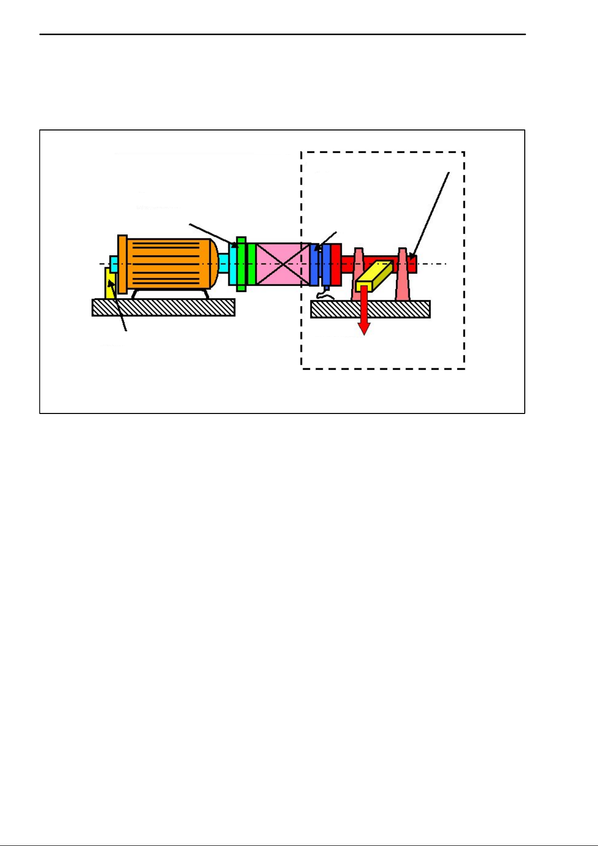
Transfertorque transducer
The main applications are torque transfer, for example, when calibrating
reference transducers in test and calibration machines and comparisons of
the reference normals of various calibration laboratories.
In the case of transfer transducers, a high degree of comparability is import
ant, as when relaying torque, this provides a gage for various observers, test
conditions, laboratories and the installation and time situation. So for relay, the
same installation conditions should be created as for calibration in the refe
rence normal, or relevant adapters (for recommendations, see Page 17f)
should be included in the calibration.
Reference torque transducer
Reference torque transducers are mounted in a calibration device and then
the entire calibration machine is qualified or certified by means of transfer
torque transducers, for example. The precise sensitivity of the transducer is
thus less important.
General torque measurements in nonturning mode
Because of the high mechanical loading capacity, the permissible vibration
bandwidth of 160% (10kN⋅m=120%) of nominal torque and the compact
design, the transducers are also eminently suitable for use in testing
machines for component testing (rotary alternating stress) or as reaction
torque transducers, for example in agitators with direct drive motor or gearbox
connection.

9
TB1A
HBMA01627.0en/de/fr
3Structure and mode of operation
3.1 Mechanical structure
The reference torque measuringdisc comprises a measuring body applied
with strain gages and a mounting flange screw fitted to it.
Measuring body
Mounting flange
Measuring side
Fig.3.1: Mechanical structure
4 Mounting
4.1 General installation notes
When the torque measuringdisc is fitted in test benches, the test bench
components (frame, couplings, mounting flanges, screw fittings, etc.), affect
the deflection performance in the shaft run and thus the measuring
characteristics (zero point, sensitivity, reproducibility). The causes for this can
include:
•Additional parasitic loadings such as radial forces, axial forces or bending
moments
•Asymmetrical torque introduction in the transducers

10 TB1A
HBM A01627.0en/de/fr
•Different stiffness conditions in the shaft run to those of transducer
calibration
These test bench reactions on the reference transducer are calibrated in by
adaptable leverground systems, for example.
Torque transducer
to be calibrated
Blocking device
TB1A
Leverforce device
for static torque
Calibration test device with
reference transducer
Fig.4.1: Typical installation in a calibration test device
Parasitic loadings
Parasitic loadings are caused by deformations in the shaft run. They result in
an additive effect on the zero signal of the torque measuringdisc (see
Specifications). If they occur during a torque loading, they cause an apparent
change in sensitivity.
Countermeasures:
1. Optimum alignment of the shaft run (note alignment data in the
Specifications!).
As long as you do not exceed the permissible limits for bending moments,
transverse force and longitudinal force, no special couplings or other
measures are required to install the reference torque measuringdisc
(effect on the measurement result approx. 1% of nominal torque).

11
TB1A
HBMA01627.0en/de/fr
2. If you cannot achieve the requisite alignment accuracy, use noninteracting
couplings.
3. Keep the weight of the shaft sections acting on the torque measuringdisc
as low as possible.
Depending on the design of the test bench, decoupling measures with
torsionally stiff but pliable torsion bars may be necessary.
Different stiffness conditions
If the stiffness conditions in the shaft run (near the torque measuringdisc)
differ to the conditions during calibration in the HBM normal measuring device,
this can change the torque introduction to the torque measuringdisc.
Countermeasures:
1. Keep strictly to the prescribed fastening bolt tightening torques.
2. Use highstrength or hardened adaptation components, especially close to
the torque introductions and torque outlets of the torque measuringdisc.
Asymmetrical torque distributions
Asymmetrical (axially uneven) torque distribution in the shaft run can lead to
deflections, that then cause parasitic loadings.
Countermeasures:
1. Use all the available screw connections for the mounting.
2. Keep strictly to the prescribed fastening bolt tightening torques.
3. Avoid making unnecessary bore holes in the adaptation flanges.
4. Use flange surfaces that are clean, flat and as polished as possible.
5. Avoid having torque introductions and outlets right on the outside diameter
of the measuring disc.
6. Use adaptation flanges with sufficiently large clearance bores to stop the
screws locking up.

12 TB1A
HBM A01627.0en/de/fr
4.2 Mounting position
The reference torque measuringdisc can be installed in any position. With
clockwise momentum, there is a positive output signal in conjunction with the
HBM measuring amplifiers.
4.3 Conditions on site
The TB1A reference torque measuringdiscs are protected to IP54 according
to EN60529. The measuringdiscs must be protected from dirt, dust, oil,
solvents and humidity.
During operation, the prevailing safety regulations for the security of
personnel must be observed.
4.4 Mechanical installation
NOTE
Handle the reference torque measuringdisc carefully. The transducer
might sufferpermanent damage from mechanical shock (dropping),
chemical effects (e.g. acids, solvents) orthermal effects (hot air, steam).
CAUTION
You must not loosen the screwed joints of the measuring body and
mounting flange and the slotted screws of the identification plate
marked at the factory by safety paint.

13
TB1A
HBMA01627.0en/de/fr
When installing the reference torque measuringdisc as a comparison
standard in calibration test benches, the torque to be measured is introduced
from the measuring side (see Fig.4.2).
Slotted screws
Identification plate
Screwed joint
Measuring body mounting flange
Measuring side
Fig.4.2: Screwed joints painted at the factory
Assembly sequence:
1. Use flange surfaces (minimum material strength>900N/mm2;
hardness>30HRC) that are clean, flat (runout tolerance 0.01mm) and
as polished as possible ( Rt<0.8).
2. Prior to installation, clean the plane flange surfaces of the
torquemeasuring disc and of the counter flanges. For safe torque transfer,
the surfaces must be clean and free from grease. Use a piece of cloth or
paper soaked with a solvent. Make sure that no solvent drips into the
gaging flange’s interior.
3. Use eight DINENISO 4762; black/oiled/mtot=0,125 hexagonsocket
screws, property class 10.9 (measuring range 10kN⋅m: 12.9), of the
appropriate length (depending on the connection geometry, see Table4.1)
to screwfasten the measuring body.
We recommend, particularly for 100N⋅m and 200N⋅m situations,
fillisterhead screws DINENISO 4762 or similar, blackened,
smoothheaded, permitted size and shape variance in accordance with
DINISO 4759, Part 1, product class A.

14 TB1A
HBM A01627.0en/de/fr
WARNING
The screw heads (Z), see Fig.4.3, must not sit on the mounting flange.
With alternating loads: glue all the connection screws into the counter
thread with a screw locking device (medium) to exclude a pretension
loss due to screw slackening.
4. With a cut thread, the adapter material should have a yield point of at least
900 N/mm2.
Screwed joint
measuring body
Screwed joint
mounting flange
Z
Fig.4.3: Screwed joint of the measuring body
5. Before finally fastening the screws, turn the reference torque
measuringdisc on the centering until all screw heads are located about
centrically in the connection element’s clearance bores. The screw heads
may in no case be in contact with the sides of the mountingflange
clearance bores.
6. Fasten all screws with the specified tightening torque (Table4.1).
7. For further installation of the shafting, there are eight threaded bores on
the mounting flange. Also use screws of property class 10.9 and fasten
with the tightening torque specified in Table4.1.

15
TB1A
HBMA01627.0en/de/fr
CAUTION
It is essential to keep to the maximum thread reach in the mounting
flange (as perTable4.1) ! Otherwise, considerable measurement errors
might occurorthe transducermight sufferdamage.
Nominal
torque
(NVm)
Fastening
bolts (Z)
measuring
body
Fastening bolts
property class
Maximum thread reach
(Y) of the screws in the
mounting flange
(mm)
Prescribed
tightening torque
(NVm)
100 M6
10.9
7.5 14
200 mM8 11 34
500 M12 18 115
1k M12 18 115
2k M14 18 185
5k M18 33.5 400
10k M18 12.91) 33.5 470
Table4.1: Fastening bolts
1) If screws of Class 12.9 are not available, Class 10.9 screws (400 N⋅m tightening torque)
can be used. The permissible limiting torque is reduced then to 120% referred to MN.
Z
Torque measuringdisc
Max. thread reach Y
Fig.4.4: Installation example

16 TB1A
HBM A01627.0en/de/fr
Installing as a transfertransducer
Transfer transducers must be as insensitive as possible to all installation
influences. This can be achieved in the design, for example, by specially
developed adaptation flanges.
For optimum transfer of sensitivity, observe the following points in addition to
the recommendations for reference transducers already mentioned:
•Introduce the torque into the torque measuringdisc from the inside (DI) to
the outside (DA), at a ratio of DI
DAv0.6 .
•The width of the adaptation flange (B) on the reaction side should be 1.5 −
2 times the diameter of the flange screw.
DI
DA
TB1A measuring side
TB1A reaction side
Adaptation flanges
B
Fig.4.5: Adaptation flange transfer transducer

17
TB1A
HBMA01627.0en/de/fr
As an alternative to shaft stubs, you can also use an additional adaptation
flange that is mounted on the sensor side and is included in the measurement
(see Fig.4.6).
DOn
TB1A
L
L > DOn
2
Z
Adaptation flange
Fig.4.6: Additional adaptation flange for transfer transducers
To make it easy to install the gaging flange with the adaptation flange, we
recommend the following flange design:
•Provide clearance bores on the reverse of the flange to correspond to the
bore pattern of the TB1A. The relative position of the clearance bores
should correspond to the relative position of the tapped holes of the TB1A.
•The dimensions of flange clearance Z must be such that the connection
screws can be put through and tightened with a torque wrench.

18 TB1A
HBM A01627.0en/de/fr
4.5 Loading capacity
The torque measuringdiscs can be used to measure static and dynamic
torques.
Please note the following when measuring dynamic torque:
•The calibration made for static torques is also valid for dynamic torque
measurements.
•The natural frequency f0for the mechanical measuring system depends on
the moments of inertia J1and J2of the connected rotating masses and the
TB1A’s torsional stiffness.
Use the below equation to determine the natural frequency f0for the
mechanical measuring system:
f0+1
2p· c
T·1
J1
)1
J2
f0= Natural frequency in Hz
J1, J2= Mass moment of inertia in kgm2
cT= Torsional stiffness in N⋅m/rad
•The maximum permissible amplitude of vibration (peaktopeak) may be
160% (at nominal torque 10 kN⋅m=120%) of the TB1A’s nominal torque,
even with alternating load. In all cases the vibration bandwidth must lie
within the loading range defined by −MNand +MN.
Caution: Even in a resonance situation, you must keep to the mechanical
limits. Torsion spring rigidity and moment of inertia for estimating the the
natural frequency, can be found in Chapter 8.
+MN100%
−MN100%
0
90
70
Nominal torque MNin %
160% (120%)MN
vibration bandwidth
Fig.4.7: Permissible dynamic loading

19
TB1A
HBMA01627.0en/de/fr
5 Electrical connection
Reference torque measuringdiscs are equipped with a fixed 6wire
connection cable (six wire circuit) with free ends. A connector assembly is
possible on request (see Chapter7.)
Extension cables should be shielded and lowcapacitance. HBM provides
cables 1−KAB0304A−10 (readymade) and KAB8/002/2/2 (by the meter, can
also be supplied with fitted appliance connector) especially for this.
The pin assignment for HBM measuring amplifiers can be found in the
following table:
Connection to a measuring amplifier
with
Connection Wire colour15pin
SubDconnector
7pin
connector
Measurement signal (+UA) White 8 A
Excitation voltage (−UB) Black 5 B
Excitation voltage (+UB) Blue 6 C
Measurement signal (−UA)Red 15 D
Sensor circuit (−) Gray 12 G
Sensor circuit (+) Green 13 F
Shielding connected to enclosure
ground Yellow 1 E
Table5.1: Pin assignment
The measuring amplifier pin assignments with soldered or clamped
connection can be found in the documentation of the particular amplifier.

20 TB1A
HBM A01627.0en/de/fr
5.1 Notes forcabling
Electrical and magnetic fields often cause interference voltages to be injected
into the measuring circuit. This interference starts primarily from power lines
lying parallel to the measuring leads, but can also start from any contactors or
electric motors in the vicinity. In addition, interference voltages can be injected
galvanically, especially if the measurement chain is grounded at several
points.
Please take note of the following:
•Use only shielded and lowcapacitance measurement cables from HBM.
•Do not install measurement cables parallel to power lines or control
circuits. If this is not possible (e.g. in cable shafts), protect the
measurement cable by armoured steel tubing, for example and keep it a
minimum of 50cm away from other cables. Power lines or control circuits
should be twisted together (15 twists per meter).
•The stray fields of transformers, motors and contactors should be avoided.
•Do not ground transducers, amplifiers and indicating instruments
repeatedly. All the devices of the measurement chain should be connected
to the same grounded conductor.
•The shield of the connection cable is connected to the transducer housing.
•Connection diagram, grounding concept (Greenline).
Grounding concept (Greenline).
The cable shielding is connected in accordance with the Greenline concept.
This encloses the measurement system in a Faraday cage. Any
electromagnetic interference active here does not affect the measurement
signal. Special electronic coding methods are used to protect the transmission
path from electromagnetic interferences.
In the case of interferences due to potential differences (compensating
currents), operatingvoltage zero and housing ground must be disconnected
on the amplifier and a potential equalization line between housing and
amplifier housing must be established (highly flexible stranded wire, 10mm2
wire crosssection).
Other manuals for TB1A
1
Table of contents
Languages:
Other HBM Transducer manuals
Popular Transducer manuals by other brands

Agilent Technologies
Agilent Technologies IMG-300 instruction manual

Balluff
Balluff BTL7-S5-M Series user guide

TR-Electronic
TR-Electronic LMRS-27 Interface-Box ANA-I manual

promesstec
promesstec UMU 100-A-B user manual

Balluff
Balluff BTL6-V11V-M Series manual

CCS
CCS WattNode Pulse WNB-3Y-208-P Installation and operation manual