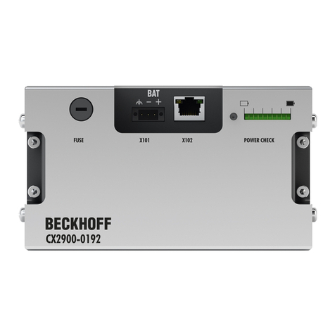
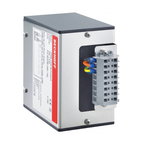
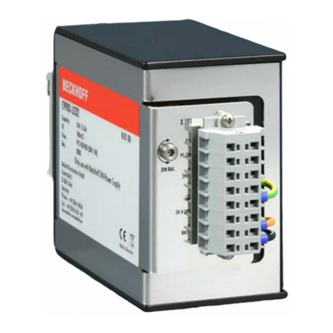
Beckhoff C9900-U330 User manual

Manual | EN
C9900-U330
Battery pack
2022-4-14 | Version: 3.0


Table of contents
C9900-U330 3Version: 3.0
Table of contents
1 Notes on the documentation ....................................................................................................................5
2 For your safety...........................................................................................................................................6
2.1 Description of safety symbols............................................................................................................6
2.2 Intended use......................................................................................................................................6
2.3 Fundamental safety instructions........................................................................................................7
2.4 Operator's obligation to exercise diligence ........................................................................................7
3 Product overview.......................................................................................................................................8
3.1 Structure ............................................................................................................................................8
3.2 Name plate ........................................................................................................................................9
4 Commissioning........................................................................................................................................10
4.1 Transport and unpacking.................................................................................................................10
4.2 Dimensions......................................................................................................................................11
4.3 Control cabinet installation ..............................................................................................................12
4.4 Connect battery pack.......................................................................................................................13
5 Decommissioning....................................................................................................................................17
6 Maintenance.............................................................................................................................................19
7 Technical data..........................................................................................................................................20
8 Appendix ..................................................................................................................................................21
8.1 Service and support.........................................................................................................................21
8.2 Approvals.........................................................................................................................................22

Table of contents
C9900-U3304 Version: 3.0

Notes on the documentation
C9900-U330 5Version: 3.0
1 Notes on the documentation
This description is only intended for the use of trained specialists in control and automation engineering who
are familiar with the applicable national standards.
The following instructions and explanations must be followed during installation and commissioning of the
components. The responsible staff must ensure that the application or use of the products described satisfy
all the requirements for safety, including all the relevant laws, regulations, guidelines and standards.
Disclaimer
The documentation has been prepared with care. The products described are, however, constantly under
development. For that reason the documentation is not in every case checked for consistency with
performance data, standards or other characteristics. In the event that it contains technical or editorial errors,
we retain the right to make alterations at any time and without warning. No claims for the modification of
products that have already been supplied may be made on the basis of the data, diagrams, and descriptions
in this documentation. All illustrations shown are only examples. The configurations depicted may deviate
from the standard.
Trademarks
Beckhoff®, TwinCAT®, TwinCAT/BSD®, TC/BSD ®, EtherCAT®, EtherCAT G®, EtherCAT G10®, EtherCAT P®,
Safety over EtherCAT®, TwinSAFE®, XFC®, XTS® and XPlanar® are registered and licensed trademarks of
Beckhoff Automation GmbH.
Other designations used in this publication may be trademarks whose use by third parties for their own
purposes could violate the rights of the owners.
Patents
The EtherCAT Technology is covered, including but not limited to the following patent applications and
patents: EP1590927, EP1789857, EP1456722, EP2137893, DE102015105702 and similar applications and
registrations in several other countries.
Copyright
© Beckhoff Automation GmbH & Co. KG. Publication of this document on websites other than ours is
prohibited. Offenders will be held liable for the payment of damages. All rights reserved in the event of the
grant of a patent, utility model or design.
Delivery state
All the components are supplied in particular hardware and software configurations appropriate for the
application. Changes to the hardware or software configuration are permitted, provided they are within the
specified limits for power consumption and power loss (please refer to the respective data sheet).
Delivery conditions
In addition, the general delivery conditions of the company Beckhoff Automation GmbH & Co. KG apply.

For your safety
C9900-U3306 Version: 3.0
2 For your safety
The Safety chapter first explains the safety symbols used in the documentation and their meanings. They
contain fundamental safety instructions that are essential for the avoidance of personal injuries and damage
to property.
Exclusion of liability
Beckhoff shall not be liable in the event of non-compliance with this documentation and thus the use of the
battery packs outside the documented operating conditions.
2.1 Description of safety symbols
The following safety symbols are used in these operating instructions. In order to avoid personal injuries and
damage to property, read and follow the safety and warning notices.
Warning of personal injuries:
DANGER
Disregarding the safety notice will lead to death or serious injuries.
WARNING
Disregarding the safety notice may lead to death or serious injuries.
CAUTION
Disregarding the safety notice may lead to minor injuries.
Warning of damage to property:
NOTE
Disregarding the notice may lead to damage to property.
2.2 Intended use
The battery pack is designed for DIN rail mounting in control cabinets of machine and system engineering. It
serves PCs with 24V power supply unit and integrated C9900-P209 or C9900-U209 UPS as external energy
storage.
The specified limits for technical data must be adhered to.
The battery pack can be used within the documented operating conditions.
Improper use
Do not use the battery pack outside the documented operating conditions.

For your safety
C9900-U330 7Version: 3.0
2.3 Fundamental safety instructions
The following safety instructions must be observed when handling the battery pack.
Application conditions
• Do not use the battery pack under extreme environmental conditions.
• Never use the battery pack in potentially explosive atmospheres.
• Provide openings in the control cabinet walls for sufficient ventilation of the control cabinet in
accordance with EN 50272-2. This avoids the risk of explosion due to gas escaping from the battery
packs.
• Never plug or unplug connectors during thunderstorms. There is a risk of electric shock.
• Ensure protective earthing of the battery pack.
Damage to property and impairment of functions
• Ensure that only trained specialists with a control and automation engineering background, operate the
PC to which the battery pack is connected. Use by unauthorized persons can lead to damage to
property.
• Extinguish the battery pack with foam halogens in case of fire or with a large amount of spray water in
case of large fires.
2.4 Operator's obligation to exercise diligence
The operator must ensure that
• the products are only used as intended (see chapter 2.2 Intended use [}6]).
• the products are only operated in sound condition and in working order.
• only sufficiently qualified and authorized personnel operate the PC to which the battery pack is
connected.
• the personnel is instructed regularly about relevant occupational safety and environmental protection
aspects, and is familiar with the operating instructions and in particular the safety instructions contained
herein.
• the operating instructions are in good condition and complete, and always available for reference at the
location where the products are used.

Product overview
C9900-U3308 Version: 3.0
3 Product overview
The battery pack C9900-U330 serves as energy storage for PCs with 24 V power supply unit and integrated
UPS and continues to supply the PC with energy in the event of a power failure. It allows backing up the data
to a hard disk or flash media (e.g. SSD or CFast) and shutting down the PC properly. The battery pack is
intended for external mounting in control cabinets of machine and system engineering.
The battery pack has a nominal capacity of 3.4Ah.
The internal structure of the battery pack consists of two 12V batteries in series connection. The VRLA-AGM
technology (valve regulated lead acid absorbed glass mat technology) is applied. These are valve regulated
lead-acid batteries with fiberglass mats in the separator.
3.1 Structure
1
2
3
Fig.1: C9900-U330_Structure
Table1: Key for C9900-U330 structure
No. Component Description
1 Name plate Information about the equipment of the battery pack
2 Socket head screws Screws for securing the battery pack on the DIN rail
3 5-pin terminal strip Connecting the battery pack to the power supply unit of the
PC

Product overview
C9900-U330 9Version: 3.0
3.2 Name plate
The name plate provides information about the battery pack equipment.
1
2
3
4
5
6
7
9
10
8
Fig.2: C9900-U330_name plate
Table2: Key for C9900-U330 name plate
No. Description
1 Model
2 Nominal capacity
3 Internal resistance
4 Fuse
5 Revision
6 Address of the vendor
7 Coded production date
8 Symbols
Note: here are the symbols applicable to the battery pack such as CE, EAC, UKCA, . The
approvals of your battery pack can be found on the name plate and in chapter 9.2 Approvals
[}22].
9 Reference to safety and warning instructions, power supply and battery leakage protection
10 Pin assignment of the 5-pin terminal strip

Commissioning
C9900-U33010 Version: 3.0
4 Commissioning
In order to use the battery pack, you must first transport and unpack it. You can then install the battery pack
in the control cabinet and connect it to the PC.
4.1 Transport and unpacking
Note the specified transport and storage conditions (see Chapter 7 Technical data [}20]).
The battery pack contains two leak-proof VRLA batteries. The batteries are permanently installed in a
corrosion-resistant stainless steel housing and short-circuit proof with electrical fuse protection.
Despite the robust design of the unit, the components are sensitive to strong vibrations and impacts.
Transporting a control cabinet with a built-in battery pack can result in excessive impact on the DIN rail and
the battery pack. Therefore, the transport of the battery pack in the control cabinet is not possible. During
transport the battery pack must therefore be protected from excessive mechanical stress. Appropriate
packaging of the battery pack, in particular the original packaging, can improve the vibration resistance
during transport.
On our original packaging you will find the following sticker:
C9900-U330 battery pack for USV
Fig.3: C9900-U330_shipping label
Use the original packaging for re-transportation to ensure the required labeling of the battery packs by the
sticker.
The battery pack is not regulated for air transport as it meets the requirements of Special Provision - "A67"
according to the International Air Transportation Association (IATA) and the International Civil Aviation
Organization (ICAO).
In addition, the battery pack meets vibration and differential pressure tests in accordance with International
Maritime Dangerous Goods (IMDG) regulations.
Unpacking
Proceed as follows to unpack the battery pack:
1. Check the packaging for transport damage.
2. Remove packaging.
3. Keep the packaging for possible future transport.
4. Check your delivery for completeness by comparing it with your order.
5. Check the contents for visible shipping damage.

Commissioning
C9900-U330 11Version: 3.0
6. In case of discrepancies between the package contents and the order, or in case of transport damage,
please inform Beckhoff Service (see Chapter 8.1 Service and support [}21]).
4.2 Dimensions
All dimensions are in mm.
Figure 4 shows the dimensions of the battery pack for correct mounting on the DIN rail.
157 175
70
Fig.4: C9900-U330_dimensions

Commissioning
C9900-U33012 Version: 3.0
4.3 Control cabinet installation
WARNING
Risk of deflagration
A missing or insufficient ventilation of the control cabinet in which the battery pack is mounted can lead to
deflagration in the control cabinet.
• Ensure sufficient ventilation of the control cabinet according to EN 50272-2 (see below).
NOTE
Extreme environmental conditions
Extreme environmental conditions can cause damage to the battery pack.
• Avoid extreme environmental conditions.
• Protect the battery pack from moisture and heat.
Ventilation control cabinet
In the event of a fault or heavy load, hydrogen may leak from the batteries inside the battery pack. Oxygen is
present in the control cabinet. If the hydrogen cannot escape from the control cabinet and the hydrogen
concentration in the control cabinet exceeds a value of 4%vol, an explosive mixture is formed and
deflagration may occur in the control cabinet. To keep the hydrogen concentration in the air low and thus
reduce the risk of deflagration, you must ensure appropriate ventilation of the control cabinet in accordance
with EN 50272-2. You can achieve this through natural ventilation. Equip the control cabinet with openings
for air circulation. Position the openings either on opposite walls or in the same wall at least 2m apart.
Control cabinet installation
The battery pack C9900-U330 is designed for installation in control cabinets of machine and plant
technology. The environmental conditions specified for operation must be observed (see chapter 7 Technical
data [}20]).
If you need the dimensions of the battery pack for mounting, you can get them in chapter 4.2 Dimensions
[}11].
The C9900-U330 battery pack is mounted on the DIN rail via the back of the battery pack. Two types of DIN
rail are commonly used in system engineering:
• TS 35 x 7.5
• TS 35 x 15
A flat DIN rail of type TS 35 x 7.5 is too weak for the battery pack. Accordingly, you may only mount the
battery pack on a DIN rail of type TS 35 x 15.
To mount the battery pack on the DIN rail, follow the steps below, shown in Figure 5:
1. Place the battery pack on the DIN rail via the rear side (section A).
2. Tighten the four socket head screws (section B).
ðYou have installed the battery pack on the DIN rail.
A B
Fig.5: C9900-U330_DIN rail installation

Commissioning
C9900-U330 13Version: 3.0
4.4 Connect battery pack
CAUTION
Risk of electric shock
Dangerous touch voltages can lead to electric shock. To avoid electric shock, observe the following:
• Never plug or unplug the battery pack cable during a thunderstorm.
• Provide protective earthing for handling the battery pack.
NOTE
Incorrect connection procedure
Incorrect procedure when connecting the cable can cause hardware damage.
• Follow the documented procedure for connecting the cable.
• Always connect the cable first and only then switch on the power supply of the connected PC.
After you have mounted the battery pack in the control cabinet, you can connect it to the PC.
Grounding
Potential differences are minimized and electrical currents are diverted to the ground through protective
earthing or potential equalization of electronic devices. This is to prevent dangerous touch voltages and
electromagnetic interference.
Connecting the battery pack
You must connect the battery pack to the PC. For this purpose, there is a 5-pin 2-wire terminal strip with
mounting flange on the battery pack housing (see Fig. 6).
15
Fig.6: C9900-U330_position terminal strip
Table3: Pin assignment terminal strip
Pin Function
1 - 24V battery pack
2 +
3
4 0V Power supply
5 24V
You can connect two wires on each side of a terminal of the terminal strip. For this purpose, you must use
double wire end sleeves (see Fig. 7).
Fig.7: C9900-U330_double wire end sleeve
PIN 4 and 5 of the battery pack are available for looping through a 24V power supply to the PC. Accordingly,
you can connect a three-core sheathed cable with plus and minus of the supply voltage as well as protective
earth to the battery pack and then connect the battery pack to the PC with a five-core sheathed cable.

Commissioning
C9900-U33014 Version: 3.0
If the supply voltage fails, the PC draws the voltage from the charged battery pack, which saves the data and
allows the PC to shut down properly.
The intended wiring of the battery pack can be found in the following wiring diagrams suitable for your
device.
12
GND
+24 V
PTC
24 V/3,4 Ah 30 V/9 A
C9900-U330 battery pack
345
1 2 3 45678
Battery
24 V
Power
24 V DC
+UPS
+ +
PC_ON
Power status
-
-
Industrial PC power connector
L max = 10 m
1,5 mm / AWG14
2
0 V24 V DC
-+
UPS Output
X1
X2
Power status
X1 X2
ext. switch
N0 N0
Fig.8: C9900-U330_wiring diagram-8-pin

Commissioning
C9900-U330 15Version: 3.0
24 V DC
PC_ON
Power status
UPS
OUT
1
2
3
4
5
ext. switch
UPS Output
ext. Switch
NO NO
X2 X1
UPS Output
X2 X1
24 V DC
0 V
Industrial PC
power connector
Power
24 V DC
Battery
24 V
1,5 mm2
Lmax = 10 m
PTC
24 V/3, 4 Ah 30 V/9 A
C9900-U330 battery pack
+24 V
GND
1
2
3
4
5
12345
Fig.9: C9900-U330_wiring diagram-2x5-pin

Commissioning
C9900-U33016 Version: 3.0
24 V DC
PC_ON
Power status 1
2
3
ext. switch
ext. Switch
NO NO
X2 X1
X2 X1
24 V DC
0 V
Industrial PC
power connector
Power
24 V DC
Battery
24 V
1,5 mm2
Lmax = 10 m
PTC
24 V/3, 4 Ah 30 V/9 A
C9900-U330 battery pack
+24 V
GND
1
2
3
4
5
12345
Fig.10: C9900-U330_wiring diagram-5-and-3-pin

Decommissioning
C9900-U330 17Version: 3.0
5 Decommissioning
WARNING
Risk of injury and hardware damage in the event of a short circuit
The batteries can be charged with large amounts of energy. In the event of a short circuit, these can lead to
very high currents, which can damage tools and injure users.
• Avoid injuries due to flying sparks and fires as well as damage to the tool by handling the battery pack
safely.
NOTE
Hardware damage due to power supply
A connected power supply can cause damage to the battery pack during disassembly.
• Disconnect the cable to the PC and thus the power supply before starting disassembly.
When decommissioning the battery pack, you must first remove all cables connected to the battery pack.
You can then remove the battery pack from the control cabinet.
If you do not want to continue using the battery pack, you will receive information on the correct disposal of
the battery pack in the further course of the chapter.
Disassembly from the DIN rail
To remove the battery pack from the DIN rail, follow the steps below, shown in Figure 11:
1. Loosen the four hexagon socket screws on the mounting notches (section A).
2. Remove the battery pack from the DIN rail (section B).
ðYou have removed the battery pack from the DIN rail.
BA
Fig.11: C9900-U330_disassembly from the DIN rail
Disposal of the battery pack
When disposing of the battery pack, be sure to observe the national electronic waste regulations.
For disposal, you must remove and dismantle the battery pack.
To dismantle the battery pack, follow the steps shown in the figure 12:
1. Remove the four M4 x 20 screws and the four M4 x 8 screws (section A).
2. Pull the angle plate from the housing (section B).
3. Remove the mounting elements (section C).
4. Pull off the fire protection plate (section D).

Decommissioning
C9900-U33018 Version: 3.0
A B
CD
Fig.12: C9900-U330_dismantling battery pack
After you have dismantled the battery pack, you should insulate the terminals of the removed batteries. For
this purpose, you can use, for example, insulating tape. You can then dispose of the components as follows:
• Dispose of batteries properly.
• Send plastic parts (polycarbonate, polyamide (PA6.6)) for plastics recycling.
• Take the angle plate to the metal recycling collection point.

Maintenance
C9900-U330 19Version: 3.0
6 Maintenance
Maintenance measures increase the efficiency of the device by ensuring long-term functionality. Cleaning
the device contributes to this.
Beckhoff generally recommends replacing the battery pack 5 years after production. You can find the coded
production date of your battery pack on the name plate. The coding is as follows:
• Example: V0916 = 16.09.2021
• V = the coded production year 2021
• 09 = Production month September
• 16 = Manufacturing day
The years of manufacture are coded in letters as follows:
• Letters H to V = production years 2007-2021
Cleaning
NOTE
Unsuitable cleaning agents
The use of unsuitable cleaning agents can damage the device.
• Clean the battery pack only as specified.
It is essential to observe the following points when cleaning the battery pack:
• Make sure that no dust gets into the battery pack.
• Only use a vacuum cleaner to clean the battery pack. The device does not have to be switched off for
this.
• Never use compressed air to clean the battery pack.
Avoid the following cleaning agents:
• Detergents with scouring or abrasive components
• Metal cleaning objects such as razor blades or steel spatulas
Repair
Only the manufacturer may repair the device. If a repair should be necessary, contact Beckhoff Service (see
Chapter 9.1 Service and support [}21]).

Technical data
C9900-U33020 Version: 3.0
7 Technical data
Product designation C9900-U330
Dimensions (W x H x D) 157 x 70 x 175 mm
Weight 3.3 kg
Electrical data Nominal voltage: 24 V
Capacity: 3.4 Ah (discharge over 20 hours)
Internal resistance: 120 mOhm
Fuse protection: 9 A/30 V via PTC element
Final charge voltage: between 27.2 V and 27.4 V
Vibration resistance (sinusoidal vibration) EN 60068-2-6: 10 to 58 Hz: 0.035 mm
58 to 500 Hz: 0.5 G (~ 5 m/s2)
Shock resistance (shock) EN 60068-2-27: 5 G (~ 50 m/s2), duration: 30 ms
EMC interference immunity conforms to EN 61000-6-2
Permitted ambient temperature 0°C to +50°C (transport/storage)
-20°C to +50°C (transport)
Permissible relative air humidity Maximum 95%, no condensation
Transport and storage The same values for air humidity and shock
resistance are to be observed during transport and
storage as in operation. The shock resistance during
transport can be improved by appropriate packaging
of the battery pack.
Table of contents
Other Beckhoff Batteries Pack manuals
Popular Batteries Pack manuals by other brands

Solax
Solax Pocket WiFi V3.0 installation manual

Anton/Bauer
Anton/Bauer QR-DSR installation instructions

Canon
Canon BATTERY PACK BP-E1 parts catalog

ENIX ENERGIES
ENIX ENERGIES MGL9050 manual

Tektronix
Tektronix THSBAT instructions

Master Battery
Master Battery GreenE 8K Installation, operation & maintenance manual