JETWAY 917PDCP User manual

917PDCP/917PDCG
917GDCP/917GDCG
USER'S MANUAL
M/B For LGA 775 Pentium 4 Processor
NO. G03-917GBA
Rev:3.0
Release date: March 2005
Trademark:
* Specifications and Information contained in this documentation are furnished for information use only, and are
subject to change at any time without notice, and should not be construed as a commitment by manufacturer.

i
USER’S NOTICE................................................................................................................................... ii
MANUAL REVISION INFORMATION ............................................................................................ ii
COOLING SOLUTIONS ...................................................................................................................... ii
CHAPTER 1 INTRODUCTION OF 917PDCP/917PDCG/917GDCP/917GDCG MOTHERBOARD
1-1 FEATURE OF MOTHERBOARD ...................................................................................... 1
1-2 SPECIFICATION.................................................................................................................. 2
1-3 PERFORMANCE LIST........................................................................................................ 3
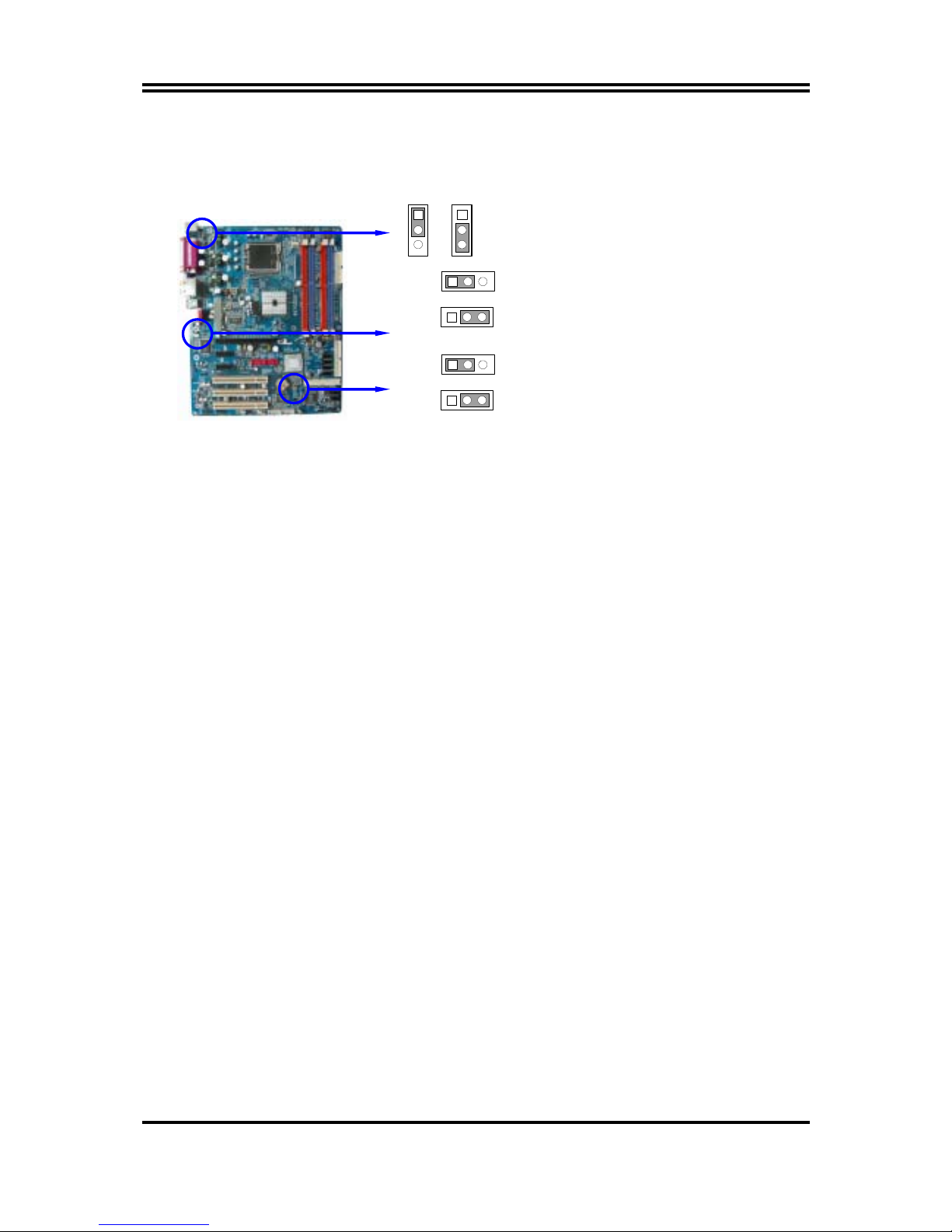
1-4 LAYOUT DIAGRAM & JUMPER SETTING ................................................................... 4
CHAPTER 2 HARDWARE INSTALLATION
2-1 HARDWARE INSTALLATION STEPS ............................................................................. 6
2-2 CHECKING MOTHERBOARD'S JUMPER SETTING................................................... 6
2-3 INSTALL CPU....................................................................................................................... 7
2-3-1 GLOSSARY................................................................................................................ 7
2-3-2 ABOUT INTEL PENTIUM 4 LGA 775 CPU.......................................................... 8
2-3-3 LGA 775 CPU INSTALLATION GUIDE................................................................ 9
2-4 INSTALL MEMORY............................................................................................................ 18
2-5 EXPANSION CARD.............................................................................................................. 19
2-5-1 PROCEDURE FOR EXPANSION CARD INSTALLATION ............................... 19
2-5-2 ASSIGNING IRQ FOR EXPANSION CARD......................................................... 20
2-5-3 INTERRUPT REQUEST TABLE FOR THIS MOTHERBOARD....................... 20
2-5-4 PCI EXPRESS SLOT ................................................................................................ 21
2-6 CONNECTORS, HEADERS ................................................................................................ 21
2-6-1 CONNECTORS.......................................................................................................... 21
2-6-2 HEADERS .................................................................................................................. 24
2-7 STARTING UP YOUR COMPUTER.................................................................................. 27
CHAPTER 3 INTRODUCING BIOS
3-1 ENTERING SETUP............................................................................................................... 28
3-2 GETTING HELP ................................................................................................................... 28
3-3 THE MAIN MENU................................................................................................................ 29
3-4 STANDARD CMOS FEATURES ........................................................................................ 30
3-5 ADVANCED BIOS FEATURES .......................................................................................... 31
3-6 ADVANCED CHIPSET FEATURES .................................................................................. 33
3-6-1 PCIEXPRESS ROOT PORT FUNCTION.............................................................. 34
3-7 INTEGRATED PERIPHERALS.......................................................................................... 35
3-7-1 ONBOARD IDE FUNCTION................................................................................... 35
3-7-2 ONBOARD DEVICE FUNCTION........................................................................... 36
3-7-3 ONBOARD SUPER IO FUNCTION ....................................................................... 37
3-8 POWER MANAGEMENT SETUP...................................................................................... 38
3-8-1 PM TIMER RELOAD EVENTS ............................................................................. 39
3-8-2 PCI EXPRESS PM FUNCTION.............................................................................. 39
3-9 PNP/PCI CONFIGURATION SETUP ................................................................................ 40
3-9-1 IRQ RESOURCES .................................................................................................... 41
3-10 PC HEALTH STATUS ........................................................................................................ 41
3-11 MISCELLANEOUS CONTROL ........................................................................................ 42
3-12 LOAD STANDARD/OPTIMIZED DEFAULTS ............................................................... 43
3-13 SET SUPERVISOR/USER PASSWORD........................................................................... 43
CHAPTER 4 DRIVER & FREE PROGRAM INSTALLATION
MAGIC INSTALL SUPPORTS WINDOWS 2000/XP................................................................. 44
4-1 INF INSTALL INTEL 915 CHIPSET SYSTEM DRIVER.................................... 45
4-2 VGA INSTALL INTEL 915G VGA DRIVER........................................................... 46
4-3 SOUND INSTALL ALC880 AC97 CODEC AUDIO DRIVER .................................... 46
4-4 LAN INSTALL REALTEK 8110S GIGA ETHERNET DRIVER .......................... 47
4-5 RAID INSTALL SIS 180 RAID DRIVER AND UTILITY........................................ 48
4-6 PC-HEALTH INSTALL INTEL HARDWARE DOCTOR UTILITY ............................ 49
4-7 PC-CILLIN INSTALL PC-CILLIN2004 ANTI-VIRUS PROGRAM .......................... 50
4-8 HOW TO UPDATE BIOS..................................................................................................... 51
TABLE OF CONTENT

ii
USER’S NOTICE
COPYRIGHT OF THIS MANUAL BELONGS TO THE MANUFACTURER. NO PART OF THIS MANUAL,
INCLUDING THE PRODUCTS AND SOFTWARE DESCRIBED IN IT MAY BE REPRODUCED,
TRANSMITTED OR TRANSLATED INTO ANY LANGUAGE IN ANY FORM OR BY ANY MEANS WITHOUT
WRITTEN PERMISSION OF THE MANUFACTURER.
THIS MANUAL CONTAINS ALL INFORMATION REQUIRED TO USE
917PDCP/917PDCG/917GDCP/917GDCG MOTHER-BOARD AND WE DO ASSURE THIS MANUAL MEETS
USER’S REQUIREMENT BUT WILL CHANGE, CORRECT ANY TIME WITHOUT NOTICE. MANUFACTURER
PROVIDES THIS MANUAL “AS IS” WITHOUT WARRANTY OF ANY KIND, AND WILL NOT BE LIABLE
FOR ANY INDIRECT, SPECIAL, INCIDENTIAL OR CONSEQUENTIAL DAMAGES (INCLUDING DAMANGES
FOR LOSS OF PROFIT, LOSS OF BUSINESS, LOSS OF USE OF DATA, INTERRUPTION OF BUSINESS AND
THE LIKE).
PRODUCTS AND CORPORATE NAMES APPEARING IN THIS MANUAL MAY OR MAY NOT BE
REGISTERED TRADEMARKS OR COPYRIGHTS OF THEIR RESPECTIVE COMPANIES, AND THEY ARE
USED ONLY FOR IDENTIFICATION OR EXPLANATION AND TO THE OWNER’S BENEFIT, WITHOUT
INTENT TO INFRINGE.
Manual Revision Information
Reversion Revision History Date
3.0 Third Edition March 2005
Item Checklist
5917PDCP/917PDCG/917GDCP/917GDCG Motherboard
5Cable for IDE/Floppy
5CD for motherboard utilities
Cable for USB Port 3/4 (Option)
5SPDIF-IN/SPDIF-OUT Adaptor
5Cable for Serial ATA IDE Port
5917PDCP/917PDCG/917GDCP/917GDCG User’s Manual
Intel Pentium 4 Processor Family
Cooling Solutions
As processor technology pushes to faster speeds and higher performance, thermal management
becomes increasingly crucial when building computer systems. Maintaining the proper thermal
environment is key to reliable, long-term system operation. The overall goal in providing the
proper thermal environment is keeping the processor below its specified maximum case
temperature. Heatsinks induce improved processor heat dissipation through increased surface area
and concentrated airflow from attached fans. In addition, interface materials allow effective
transfers of heat from the processor to the heatsink. For optimum heat transfer, Intel recommends
the use of thermal grease and mounting clips to attach the heatsink to the processor.
When selecting a thermal solution for your system, please refer to the website below for
collection of heatsinks evaluated and recommended by Intel for use with Intel processors. Note,
those heatsinks are recommended for maintaining the specified Maximum T case requirement. In
addition, this collection is not intended to be a comprehensive listing of all heatsinks that support
Intel processors.
For vendor list of heatsink and fan, please visit :
http://developer.intel.com/design/Pentium4/components/index

1
Chapter 1
Introduction of 917PDCP/917PDCG/917GDCP/917GDCG
Motherboard
1-1 Feature of motherboard
The 917PDCP/917PDCG/917GDCP/917GDCG motherboard is design for use Intel Pentium
4 Processor in LGA775(Land Grid Array) Prescott Processor with the Intel 915P/915G
Chipset delivers a high performance and professional desktop platform solution. Which utilize
the design and the memory size expandable to 2.0GB.
These motherboards use the newest Intel 915P/915G Chipset Supports 533MHz/800MHz
Processor System Bus (FSB) in data transfer rate, the 917PBAG917PBA/917GBAG/ 917GBA
provided 200/166MHz SDRAM clock frequency support DDR400/DDR333 SDRAM, also
provided DDR2 clock frequency support DDR2 533/400. These motherboard also provided
Dual Channel function to increase memory performance. The motherboard embedded ICH6
chipset offers one parallel ULTRA ATA 100 interface and four serial ATA interface to
provide speedier HDD throughout that boosts overall system performance.
917PDCP/917PDCG/917GDCP/917GDCG provided one 16-lane PCI Express port intended
for Graphics Attach, fully compliant to the PCI Express Base Specification revision 1.0a, and
two 1-lan PCI Express port support.
This X16 PCI Express Slot provided multiplexed Digital display channels, Support with
ADD2 Card (Advanced Digital Display).
The 917PDCG/917GDCG motherboard including Fast Ethernet PCI LAN chip support
10Mb/s, 100Mb/s, 1Gb/s Base transfer rate.
The 917PDCP/917GDCP motherboard including Fast Ethernet PCI LAN chip support 10Mb/s,
100Mb/s Base transfer rate.
These motherboards also has an integrated 8-channel High Definition Audio Codec on board
support 8-channel 3D surround positioning Audio which is fully compatible with Sound
Blaster Prothat gives you the best sound quality and compatibility. The motherboard
provided SPDIF-In/ SPDIF-Out optical function support SPDIF device.
With USB control as well as capability of expanding to 8 USB2.0 function ports, these
motherboards meet future USB demand also these motherboard have built-in hardware
monitor function. This will monitor and protect your computer. These motherboards special
design in hardware to protect BIOS from virus crash BIOS data.
These motherboards provide special function in BIOS Setup to setting CPU Host clock step
by step increasing let users to approach over clocking.
These motherboards provided high performance & meet future specification demand. It is
really wise choice for your computer.

2
1-2 Specification
Spec Description
Design ∗ATX form factor 4 layers PCB size: 30.5x24.5cm
Chipset ∗Intel 915P Memory Controller Hub (MCH) Chipset for
917PDCG/917PDCP
∗Intel 915G Graphics Memory Controller Hub (GMCH) Chipset
for 917GDCG/917GDCP
∗Intel 82801FB I/O Controller Hub (ICH6) Chipset
CPU Socket
(LGA 755 Socket)
∗Support Intel Pentium 4 755-Land LGA Package utilizes Flip-
Chip Land Grid Array (FCLGA4) package processor
∗Support CPU Frequency 533MHz/800MHz
∗Support 2.8G~3.8G LGA 755 Pentium 4 processor
∗Reserves support for future Intel Pentium 4 processors
Memory Socket ∗184-pin DDR RAM module socket x2
∗240-pin DDR2 RAM module socket x2
∗Support either Dual channel DDR333/DDR400 or
DDR2 533/DDR2 400 RAM Module
∗Expandable to 2.0GB
Integrate VGA
( for 917GDCG/
917GDCP)
∗400MHz Integrated 24-bit RAMDAC up to 2048x1536@75 Hz
∗Multiplexed Digital Display Channels (Support with ADD2
Card (Advanced Digital Display)
Expansion Slot &
Headers
∗One PCI Express x16, two PCI Express x1 Slots
∗32-bit PCI slot x 3
Integrate IDE ∗One IDE controllers support PCI Bus Mastering, ATA
PIO/DMA and the ULTRA DMA 33/66/100 functions that
deliver the data transfer rate up to 100 MB/s
∗Four Serial ATA Host controllers, that deliver the data transfer
rate up to 150 MB/s
LAN On Board
(Giga LAN only for
917PBAG/917GBAG)
∗Realtek 8110S PCI Interface Gigabit Ethernet (GbE) controller
∗Supports 10/100/1000 Mb/sec data transfer rate
LAN On Board
(10/100M LAN for
917PBAP/917GBAP)
∗Realtek 8100C PCI Interface Ethernet controller
∗Supports 10/100 Mb/sec data transfer rate
Audio ∗Realtek ALC880 8-channel High Definition Audio Codec
integrated
∗Support 8-channel 3D surround & Positioning Audio
∗SPDIF-In/ SPDIF-Out Optical support (Cable optional)
∗Audio driver and utility included
BIOS ∗Award 4MB Flash ROM
Multi I/O ∗PS/2 keyboard and PS/2 mouse connectors
∗Floppy disk drive connector x1
∗Parallel port x1, Serial port (x2 for 917PDCG/917PDCG, x1 for
917GDCG/917GDCP)
∗USB 2.0 connector x4, headers x4 (connecting cable option)
∗High Definition Audio connector (Line-in, MIC, 4x Line-Out)

3
1-3 Performance List
The following performance data list is the testing result of some popular benchmark testing
programs. These data are just referred by users, and there is no responsibility for different
testing data values gotten by users (the different Hardware & Software configuration will
result in different benchmark testing results.)
Performance Test Report
CPU: Intel Pentium 4 Prescott 3.6G
DRAM: PMI SAMSUNG 512M DDR2-533 X 2 1Gbyte Memory
TwinMOS Hynix Hy5du56822CT 512M DDR400 X 2 (1Gbyte) Memory
On Board VGA: On Board VGA share 32M (1024X768X32BIT Color)
Hard Disk Driver: Seagate Barracude 7200.7 SATA150
BIOS: Award Optimal default
OS: WinXPPrefessional (Service Pack 1)
917GBAG Onboard VGA +
DDR400
Onboard VGA +
DDR2-533
3D Mark 2001SE 5142 5448
3D Mark 2003 1301 1373
3D Mark 2005 249 271
AQUAMRK3 (GFX / CPU) 8277 (870 / 8235) 8828 (930 / 8552)
PCMark2004
System / CPU / Memory 3332 / 3609 / 4316 3499 / 3657 / 4323
Graph / HDD 995 / 4181 1036 / 4180
Content Creation Winstone 2004 27 27.9
Business Winstone 2004 20.8 22.4
Winbench 99 V2.0:
Business/Hi-end Disk Winmark99 7260 / 30600 7420 / 27300
Business/Hi-end Graphic Winmark 378 / 1010 381 / 1010
SISMark 2004: SISMark Rating(Internet Content Creation / Office Productivity )
SISMark 2004 164 (164 / 164) 160 (158 / 161)
3D Creation / 2D Creation 174 / 176 163 / 181
/ Web publication 143 133
Communication / Document Creation 149 / 168 145 / 164
/ Data Analysis 177 174
SISOFT Sandra 2004 : 1.CPU Arithmetic Benchmark 2.Memory bandwidth Benchmark 3.CPU
Multi-Media Benchmark
1.Dhrystone ALU MIPS 8106 7939
Whetstone FPU iSSE2 FLOPS 4242 / 5790 4248 / 5742
2.Int/Float Buffered iSSE2 MB/S 4442 / 4442 4650 / 4683
3.Integer/Floating-Point SSE2 IT/S 25052 / 29049 24823 / 28404
UT2003 Benchmark (flyby/botmatch) 75.52 / 27.83 78.82 / 30.65
Quake3 DEMO1 / DEMO2 FPS 129.9 / 123.4 134.2 / 130.1
Return to Castle Wolfenstein FPS 78.8 79.1
Super Pi (1M) Second 37s 36s
CPUZ System / CPU Clock 200.0 / 3600.0 200.0 / 3600.0

4
1-4 Layout Diagram & Jumper Setting
COM1 VGA
USB2
PS/2 Mouse
PS/2 Keyboard
PRINT
LAN
USB
Line-IN
MIC-IN
Line-OUT
Surrbac
k
GEN/LFE SURROUND
USB Power ON Jumper (JP3)
ATX 12V Power Connector
Floppy Connector
Intel 915G/915P Chip
ATX Power Connector
CPU FAN
CPU Socket
DDR2 DIMMx2
USB Port (USB3, USB4)
4MBit FWH BIOS
USB Power ON Jumper (JP2)
8-CH AC’97 Audio Codec
PCI EXPRESSx16
CD Audio
FINTEK F71872F LPC I/O Chip
PCI Slot
PC99 Back Panel
K/B Power ON Jumper
(JP1)
USB Port/LAN Connecto
r
PS2 KB/Mouse Port
Audio Connecto
r
PCI EXPRESSx1
USB Port Connecto
r
SYSFAN1
RTL8110S PCI LAN Controller ATA 100 IDE Connector
Serial-ATA Connector
(SATA1, 2, 3, 4)
Front Panel Connector
ATA 133 IDE Connector
Clear CMOS (JP4)
Intel 82801FB Chip
Power LED/Speak Connector
Serial-ATA RAID Port Connecto
r
(SATA5, 6)
SiS 180 Serial ATA Controller
SYSFAN2
Front Panel Audio
SPDIF Connector
IR Connector
DDR DIMMx2

5
Jumpers
Jumper Name Description Page
JP4 CMOS RAM Clear 3-pin Block P.6
JP1 Keyboard Power On Enable/Disabled 3-pin Block P.7
JP2/JP3 USB Power On Enable/Disabled 3-pin Block P.7
Connectors
Connector Name Description Page
ATXPWR ATX Power Connector 24-pin Block P.22
ATX12V ATX 12V Power Connector 4-pin Block P.22
USB1/USB2 USB Port Connector 4-pin Connector P.22
LAN LAN Connectors RJ-45 Connector P.22
PS2 KB/MOUSE PS/2 Mouse & PS/2 Keyboard
Connector
6-pin Female P.22
PARALLEL Parallel Port Connector 25-pin Female P.22
J1 Audio Line In/Out MIC Connector 6 phone jack Connector P.22
VGA
(for 917GDCG/917GDCP)
VGA Display Connector 15-pin Female Connector P.22
COM2
(for 917PDCG/917PDCG)
Serial Port COM2 Connector 9-pin Connector P.22
COM1 Serial Port COM1 Connector 9-pin Connector P.22
FDD Floppy Driver Connector 34-pin Block P.23
IDE1/IDE2 Primary/Secondary Connector 40-pin Block P.23
SATA1~4 Serial-ATA Port Connector 7-pin Block P.24
Headers
Header Name Description Page
AUDIO Line-Out, MIC Headers 9-pin Block P.24
USB3/USB4 USB Port Headers 9-pin Block P.24
SPEAK Speaker connector 4-pin Block P.25
FP
(Power LED/Reset/
IDE LED/ Power Button)
Front Panel Header
(including Power LED/ IDE activity LED/
Reset switch / Power On Button lead)
9-pin Block P.25
CPUFAN CPUFAN Power Header 4-pin Block P.25
SYSFAN1, SYSFAN2 FAN Power Headers 3-pin Block P.25
IR IR infrared module Headers 5-pin Block P.26
CDIN CD Audio-In Headers 4-pin Block P.26
JP6 (SPDIF) SPDIF In/Out Header 10-pin Block P.26
Expansion Sockets
Socket/Slot Name Description Page
LGA 775 Socket CPU Socket LGA 775 CPU Socket P.8
DIMM1, DIMM3 DDR2 Module Socket 240-pin DDR2 RAM Module
Expansion Socket
P.18
DIMM2, DIMM4 DDR Module Socket 184-pin DDR RAM Module Expansion
Socket
P.18
PCI1 ∼PCI3 PCI Slot 32-bit PCI Local Bus Expansion slots P.19
PE1 x16 PCI Express Slot x16 PCI Express Expansion Slot P.21
PE2/PE3 x1 PCI Express Slot x1 PCI Express Expansion Slot P.21

6
Chapter 2
Hardware installation
2-1 Hardware installation Steps
Before using your computer, you had better complete the following steps:
1. Check motherboard jumper setting
2. Install CPU and Fan
3. Install System Memory (DIMM)
4. Install Expansion cards
5. Connect IDE and Floppy cables, Front Panel /Back Panel cable
6. Connect ATX Power cable
7. Power-On and Load Standard Default
8. Reboot
9. Install Operating System
10. Install Driver and Utility
2-2 Checking Motherboard’s Jumper Setting
(1) CMOS RAM Clear (3-pin) : JP4
A battery must be used to retain the motherboard configuration in CMOS RAM short 1-2
pins of JP4 to store the CMOS data.
To clear the CMOS, follow the procedure below:
1. Turn off the system and unplug the AC power
2. Remove ATX power cable from ATX power connector
3. Locate JP4 and short pins 2-3 for a few seconds
4. Return JP4 to its normal setting by shorting pins 1-2
5. Connect ATX power cable back to ATX power connector
Note: When should clear CMOS
1. Troubleshooting
2. Forget password
3. After over clocking system boot fail
CMOS RAM Clear Setting
JP4
13
2-3 closed Clear CMOS
JP4
13
1-2 closed Normal (Default)

7
(2) Keyboard/USB Power On function Enabled/Disabled: JP1/JP2, JP3
When setting Enabled you can using keyboard by key in password/USB device to power
on system.
JP1 2-3 closed K/B Power ON Enabled
JP1 1-2 closed K/B Power ON Disabled (Default)
JP1
1
3
JP1
1
3
JP3 2-3 closed USB Power On Enabled
JP3 1-2 closed USB Power On Disabled (Default)JP3
13
JP3
13
JP2 2-3 closed USB Power On Enabled
JP2 1-2 closed USB Power On Disabled (Default)JP2
13
JP2
13
2-3 Install CPU
2-3-1 Glossary
Chipset (or core logic) - two or more integrated circuits which control the interfaces between
the system processor, RAM, I/O devises, and adapter cards.
Processor slot/socket/LGA - the slot or socket used to mount the system processor on the
motherboard.
Slot (PCI-E, PCI, RAM) - the slots used to mount adapter cards and system RAM.
PCI - Peripheral Component Interconnect - a high speed interface for video cards, sound
cards, network interface cards, and modems; runs at 33MHz.
PCI Express- Peripheral Component Interconnect Express- a high speed interface for video
cards, sound cards, network interface cards, and modems
Serial Port - a low speed interface typically used for mouse and external modems.
Parallel Port - a low speed interface typically used for printers.
PS/2 - a low speed interface used for mouse and keyboards.
USB - Universal Serial Bus - a medium speed interface typically used for mouse, keyboards,
scanners, and some digital cameras.
Sound (interface) - the interface between the sound card or integrated sound connectors and
speakers, MIC, game controllers, and MIDI sound devices.
LAN (interface) - Local Area Network - the interface to your local area network.
BIOS (Basic Input/Output System) - the program logic used to boot up a computer and
establish the relationship between the various components.
Driver - software, which defines the characteristics of a device for use by another device or
other software.
Processor - the "central processing unit" (CPU); the principal integrated circuit used for doing
the "computing" in "personal computer"
Front Side Bus Frequency - the working frequency of the motherboard, which is generated
by the clock generator for CPU, DRAM and PCI BUS.
CPU L2 Cache - the flash memory inside the CPU, normally Athlon CPU has 256K or above,
while Duron will have 64K.

8
2-3-2 About Intel Pentium 4 LGA775 CPU
This motherboard provides a 775-pin surface mount, LGA775 Land Grid Array socket,
referred to as the LGA775 socket supports Intel Pentium 4 processor in the 775 Pin package
utilizes Flip-Chip Land Grid Array (FC-LGA4) package technology.
The CPU that comes with the motherboard should have a cooling FAN attached to prevent
overheating. If this is not the case, then purchase a correct cooling FAN before you turn on
your system.
WARNING! Be sure that there is sufficient air circulation across the processor’s
heatsink and CPU cooling FAN is working correctly, otherwise it may
cause the processor and motherboard overheat and damage, you may install
an auxiliary cooling FAN, if necessary.
To install a CPU, first turn off your system and remove its cover. Locate the LGA775 socket
and open it by first pulling the level sideways away from the socket then upward to a 90-
degree angle. Insert the CPU with the correct orientation as shown below. The notched
corner should point toward the end of the level. Because the CPU has a corner pin for two of
the four corners, the CPU will only fit in the orientation as shown.
CPU LGA775 Socket
Colden Arrow
LGA775
When you put the CPU into the LGA775 socket. No force require to insert of the CPU, then
press the level to Locate position slightly without any extra force.

9
2-3-3 LGA 775 CPU Installation Guide
Socket Preparation
1. Opening the socket:
Note: Apply pressure to the corner with right hand thumb while opening/closing the load lever,
otherwise lever can bounce back like a “mouse trap” and WILL cause bent contacts (when
loaded)
i. Disengage Load Lever by depressing down and
out on the hook to clear retention tab
ii. Rotate Load Lever to fully open position at
approximately 135degrees
iii. Rotate Load Plate to fully open position at
approximately 100degrees
2. Remove PnP Cap (Pick & Place Cap)
i. With left hand index finger and thumb to support the load plate edge, engage PnP cap with right
hand thumb and peel the cap from LGA775 Socket while pressing on center of PnP cap to assist in
removal.
ii. Set PnP cap aside. Always put PnP cap back on if the processor is removed from the socket.
iii. Visually inspect PnP cap for damage. If damage observed, replace the PnP cap.
Note: After PnP cap removal, make sure socket
load plate and contacts are free of foreign
material; Refer to Overview Module for FM
cleaning.
Note: Optionally, remove PnP cap after CPU insertion.
This will compromise the ability to visually
inspect socket.
Socket Load
Lever Open
Socket Load
Plate Open

10
3. Visually inspect for bent contacts (Recommend at least 1stpass visual inspection)
NOTE:Refer to the Handling and Inspection Module for 1stand 2ndpass inspection details.
NOTE:Glove images are for illustrative purposes only. Please consult local safety guidelines for
specific requirements
NOTE: Recommend not to hold the load plate as a lever, instead hold at tab with left hand, removing
the PnP cap with right hand
775-land LGA Package Insertion
1. Lift processor package from shipping media by
grasping the substrate edges ONLY.
Note: Orient processor package such that the Pin 1
triangle mark is on bottom left and both key
notches are on left side
2. Land Side Cover Handling: Remove land side cover
with the opposite hand by depressing larger
retention tab and peeling the cover away
3. Set and reserve the land side cover aside.
Note: Always keep the land side cover on the
processor when not in the socket.
4. Visually inspect the package gold pads: Scan the
processor package gold pad array for presence of
foreign material. Refer to Overview Module for FM
cleaning recommendations
5. Orient the package with IHS up. Locate Pin 1 and
the two orientation key notches
6. Carefully place the package into the socket body
using a purely vertical motion
CAUTION: Using Vacuum Pen for installation is not recommended
7. Verify that package is within the socket body and
properly mated to the orient keys
8. Close the socket by
i. Rotating the Load Plate onto the package HIS
ii. While pressing down lightly on Load Plate, engage
the Load Lever.
iii. Securing Load Lever with Load Plate tab under
retention tab of Load Lever
Press to remove
Pin 1 Indicator
Alignment Key

11
775-Land Package Removal
1. Open the Load Plate/Lever with both hands:
With left hand index finger and thumb to support the
load plate edge, engage PnP cap with right hand
thumb and peel the cap from LGA775 Socket while
pressing on center of PnP cap to assist in removal.
2. Pick up 775-land LGA package:
By Vacuum Pen: Place a minimum 9-mm cup at
approximately the center of IHS.
Recommend not to place Vacuum Pen on IHS edge.
Risk of dropping and causing bent contact.
Recommend not to use Vacuum Pen for inserting
CPU By Hand: Index finger to hold load plate hinge
side and thumb to hold load lever side
3. Lift the package straight up and away.
4. Assemble processors land side cover immediately
to prevent contamination.
i. While holding the processor by the 3 corners, the
other hand lift land side cover from work surface
by grasping at the large retention tabs. Ensure
retention tabs and package are pointing each
other.
ii. Orientate so that land side cover chamfer is
matching with package Pin 1 location.
iii. Hook the first large retention tab on the package
substrate. Then press the opposite tab onto the
substrate.
iv. Place processor with land side cover installed onto
proper shipping media or other ESD approved work
surface
Chamfer on Land Side
Cover (align this with
pin 1 mark on 775-land
LGA package)
Large Retention Tabs
(pointing towards user)
Hold at corners

12
5. Visually inspect socket contact array
1. First Pass Inspection
i. Scan socket contact array at varying angles noting the presence of any foreign material
ii. If foreign material can’t be blown off by compressed air, or mechanical damage (Mode1 or 4)
observed, reject the motherboard for further evaluation or socket replacement.
2. Second Pass Inspection
i. Repeat 2 more times to sight down the rows and columns from each of the 4 sides of the socket to
ensure all contacts within the array are inspected
ii. Inspect for Mode2, Mode3, and Mode5 failures
Note: Refer to the Test Module for detail visual inspections
6. Assemble LGA775 socket PnP cap
i. Secure/Hook the back side of PnP cap.
ii. Snap down the front side to fully secure
7. Close the Socket
Intel Reference Thermal Solution Assembly
NOTE: Depending on the configuration, Thermal Solution Integration procedure could perform with
M/B alone or with M/B in the Chassis.
1. Place motherboard on support structure providing
minimum 0.150-inch backside clearance
2. Apply 300 mg of Thermal Interface Material (Shin-
Etsu G751) onto center of IHS
0.150-inch backside
clearance for
fastener installation
Fan cabled on side
closest to MB heade
r
Fastener slots
pointing straight out

13
NOTE: Thermal Solutions that come with IntelR boxed
processor use pre-applied thermal interface material
and not grease.
3. Remove Heat Sink (HS) from packaging media
4. Place HS onto the LGA775 Socket
•Ensure fan cables are oriented on side closest to
fan header
•Align Fasteners with MB through-holes
5. Inspection
•Ensure cables are not trapped or interfere fastener
operation
•Ensure fastener slots are pointing straight out from
heatsink
6. Actuate fasteners
•While holding HS to prevent tilting, press down on
fastener caps with thumb to install and lock
Repeat with remaining fasteners
7. Inspection
•Verify the fasteners are properly seated
•Ensure both fastener cap and base are flush with
spring and motherboard
8. Connect fan header with Board header
9. Secure excess cable with tie-wrap to ensure cable
does not interfere with fan operation or contact
other components.
Apply Thermal
Interface Material
Fastener Cap not
resting against spring
Fastener flush
against MB
Press Down
(4 Places)
Both fastener
halves are flush
against spring
Fastener flush
against spring

14
Intel Reference Thermal Solution Disassembly
1. Rotate fastener cap. turn to un-lock
2. Pull up fastener cap to un-seat 12
1. Disconnect fan cable from motherboard header
2. Turn fastener caps (4) counter-clock wise
90degrees to the un-locked position
•A flat-bladed screwdriver may be used if required
3. Pull up on fastener caps to unseat
4. Manually remove HS with gentle twist motion.
5. To re-assemble the HS, reset the fastener caps to
their original position with the slot perpendicular to
the HS. Then, follow the assembly instructions.
Note: Thermal grease should be reapplied
TIM and Grease Removal from CPU
1 2
3 4

15
1. Remove the heatsink from the socket
2. Gently push loose thermal interface material (TIM) to center of processor (pictures 2 and 3)
3. Remove pieces with dry cloth (picture 4)
4. Wipe with dry, lint-free cloth to remove most of the material (picture 5)
5. Wet another lint-free cloth with isopropyl alcohol (IPA) and wipe to clean remaining material
(picture 6)
6. Be careful to remove material from gaps between processor and load plate
7. For thermal grease removal use Step 4-6
TIM and Grease Removal from Heat-sink
Note: Remove and replace the TIM from the heatsink if you are re-using the heatsink on a new
processor
1. Use dry, lint-free cloth and wipe package to remove most of the material
2. Wet another lint-free cloth with isopropyl alcohol (IPA) and wipe heatsink to clean remaining
material
5 Dr
y
6IPA
Removal TIM from heatsink
1
Dr
y

16
Replacing Damaged Fasteners
•To prevent damage, avoid setting the thermal solution with the prongs down
−Set on heatsink side or with fan down
•The plastic fasteners on the heatsink can be replaced.
−Use Shop Intel to order spare fasteners
−http://www.shop-intel.com
•To remove a damaged fastener
Note: Protective gloves are not required for this procedure
−Rotate the black pin counterclockwise until it “snaps”. There will be some resistance
−Remove the black pin from the white prong
−Tilt the white prong to remove it from the heatsink leg
1
Dr
y
2
Avoid damage, avoid placing
prongs on hard surface
Damaged. Attempts to
straighten not recommended

17
Replacing Fasteners
•To replace the fastener
−Start with the white prong
−Note the “keying” notch feature
−Tilt the prong to insert into the heatsink leg.
−Holding the white prong without bending it, push the black pin on from the bottom until you hear a
single “click”
Note: The black pin and white prong will only “snap” on in one orientation
−Check to ensure the black pin is rotated properly for installation with the slot perpendicular to the
heatsink
Tilt to remove
Replacement
Tilt to insert
Click
This manual suits for next models
3
Table of contents
Other JETWAY Motherboard manuals

JETWAY
JETWAY P5M User manual

JETWAY
JETWAY JBC390F841VGU User manual

JETWAY
JETWAY V266BR4A User manual

JETWAY
JETWAY B 860T User manual

JETWAY
JETWAY S755TWIN User manual

JETWAY
JETWAY V6FP User manual

JETWAY
JETWAY JNP891P Series User manual

JETWAY
JETWAY 601TCFR3A User manual

JETWAY
JETWAY V881DASR1A User manual

JETWAY
JETWAY 865GDM User manual

JETWAY
JETWAY 916PCP User manual

JETWAY
JETWAY HA03 User manual

JETWAY
JETWAY P4MVM User manual

JETWAY
JETWAY I406R1A User manual

JETWAY
JETWAY TA75AG Series User manual

JETWAY
JETWAY 601CFR4A User manual

JETWAY
JETWAY NF596 User manual

JETWAY
JETWAY NC6J Series User manual

JETWAY
JETWAY MI05 Series User manual

JETWAY
JETWAY 693AS User manual