manuals.online logo
Brands
  1. Home
  2. •
  3. Brands
  4. •
  5. Beech ovens
  6. •
  7. Cooking Equipment
  8. •
  9. Beech ovens Exhaust Duct Design User manual

Beech ovens Exhaust Duct Design User manual

Popular Cooking Equipment manuals by other brands

Stalgast 725002 instruction manual

Stalgast

Stalgast 725002 instruction manual

Pando PI-TEP installation manual

Pando

Pando PI-TEP installation manual

Petromax h-fs56 user manual

Petromax

Petromax h-fs56 user manual

AMC Navigenio user manual

AMC

AMC Navigenio user manual

WOLL PRESSURE PRO instruction manual

WOLL

WOLL PRESSURE PRO instruction manual

Firex BETTERPAN Installation and operation manual

Firex

Firex BETTERPAN Installation and operation manual

Salvis Smartline AKC1 BI371820 operating instructions

Salvis

Salvis Smartline AKC1 BI371820 operating instructions

SousVideTools.com iVide PLUS user guide

SousVideTools.com

SousVideTools.com iVide PLUS user guide

AMC Secuquick softline user manual

AMC

AMC Secuquick softline user manual

arilex CT-4 instruction manual

arilex

arilex CT-4 instruction manual

SEVERIN TO 2065 Instructions for use

SEVERIN

SEVERIN TO 2065 Instructions for use

Stalgast 745104 instruction manual

Stalgast

Stalgast 745104 instruction manual

Firex 191BR2EA Use and installation  manual

Firex

Firex 191BR2EA Use and installation manual

Russell Hobbs 25490-56 manual

Russell Hobbs

Russell Hobbs 25490-56 manual

iglu ARCHE NOAH user manual

iglu

iglu ARCHE NOAH user manual

Kool-It KCB-60-2 Installation and operation guide

Kool-It

Kool-It KCB-60-2 Installation and operation guide

Onlyfire GS300 manual

Onlyfire

Onlyfire GS300 manual

Bartscher 150121 Original instruction manual

Bartscher

Bartscher 150121 Original instruction manual

manuals.online logo
manuals.online logoBrands
  • About & Mission
  • Contact us
  • Privacy Policy
  • Terms and Conditions

Copyright 2025 Manuals.Online. All Rights Reserved.

Exhaust Duct Design Page 1 of 16 2016-10-07 (C)
Oven Exhaust Guide Version: R5
Exhaust Duct Design
The following section is for your guidance in establishing a design to suit your
Exhaust duct design requirements.
Exhaust ductwork should be carried out by a qualified, experienced trade
team with knowledge of local authority requirements. The following
information is supplied ONLY as a guide.
NOTE: The temperature of the oven is dependent on the size of the fire and the
volume of airflow to the exhaust duct. The ’exhaust flow’ is controlled by the
system damper and the fan capacity.
Access to the system damper is required for initial adjustment, for cleaning
and maintenance and for further adjustment should ambient conditions
change.
Flue Material
Check your local authority requirements.
A variety of specialised proprietary flue systems including stainless steel twin and
triple skinned products are available and highly recommended. Beech Ovens
recommend all joins, seams and flanges to be fully sealed and preferably fully
welded. (Your local mechanical contractor should advise you of available systems.)
Recommended Flue size
300mm square or equivalent cross-sectional area in round or rectangular section. For
ducted systems more than 6 metres long or containing more than 4 bends,
professional ducting advice should be obtained.
Nominal airflow required (at Flue Connection)
150Pa Static Pressure (measured 50mm directly below to the duct connection point).
Maximum total flue airflow - 450 litres / second (at exhaust duct connection point).
The oven flue can be connected to any exhaust system with a much higher flow rate
by controlling the suction utilising an inline damper (by others).
Exhaust Duct Design_R5.doc Page 2 of 16 2016-10-07 (C)
General Information on Flues
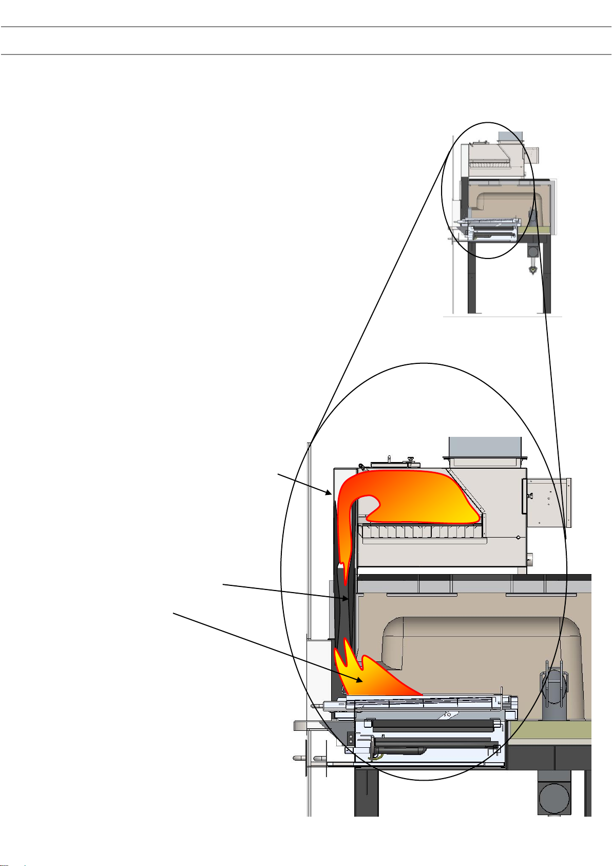
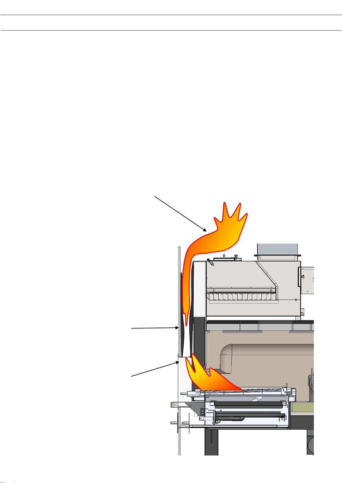
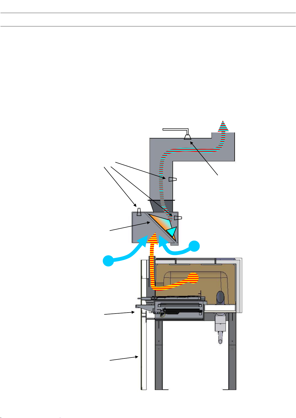
Due to the nature of wood fired ovens, the exhaust temperatures can be quite high
and sparks or embers may be present (hence fire danger should be considered.)
To avoid problems there are a number of options to be considered:
It is always important to keep the flue system clean.
When firing the oven with wood, we strongly recommend the use of good,
clean hardwood fuel only.
A build-up of soot and/or creosote in the flue is not good in
any situation. We recommend inspections every three months.
Through these regular inspections you can develop a program
for regular cleaning of your system.
Flue Fires
To reduce the possibility of flue fire we recommend the following steps.
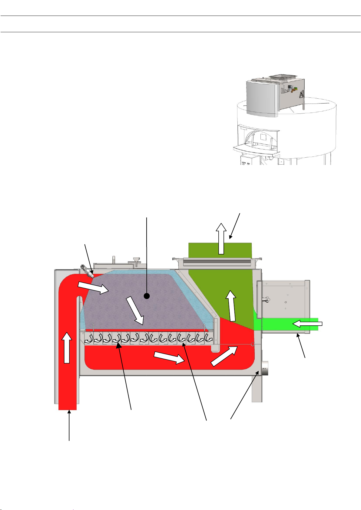
1. Keep the flue system clean. This includes the oven spigot
(prior to the Spray Filter if fitted) and all ductwork. Introduce
regular inspections to develop a program for regular cleaning
of your system.
2. For solid fuel ovens it is recommended they be connected to a dedicated
exhaust extraction system.
3. To further reduce the risk of fire, a high temperature sprinkler head can be
installed into the duct, connected to a constant/ secure water supply. This can
be included on any flue system. Contact your local fire safety consultant for
more information.
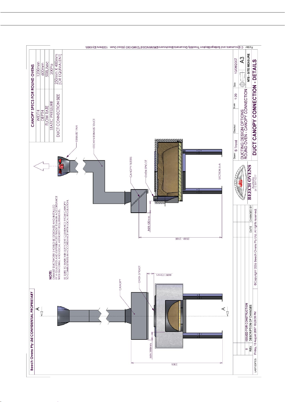
4. Where possible, if connecting to a communal kitchen extraction system,
connect oven to ducting from the dishwasher canopy.
5. For additional safety, use a Beech Oven Spray Filter.
6. Cool air from the ceiling void, restaurant or ideally from outside the building
can be introduced into the Cool Air make-up inlet.
7. Where possible, install the oven under a recommended canopy exhaust
system.
Exhaust Duct Design_R5.doc Page 3 of 16 2016-10-07 (C)
1. Grease build up on
spigot walls ignites
from flash fire on Char
Grill
THE SPIGOT WALLS
MUST BE CLEANED
DAILY OR WEEKLY
DEPENDING ON THE
GREASE BUILD UP
2. The fire, fuelled by a residual build up
of grease, fat and creosote, is drawn
into the Spray filter.
REGULAR DUCT MAINTENANCE IS
ESSENTIAL. WE RECOMMEND A 3
MONTHLY MAINTENANCE
SCHEDULE.
FIRE
Possible cause of Flue fire
Flue fires are primarily due to poor maintenance and the lack of a
rigid cleaning schedule. Most flue fires can be prevented by
implementing a regular and thorough maintenance schedule as
outlined in the Maintenance section of the Installation and
Operation Manual.
The illustration below outlines the possible cause of a flue
fire and highlights the most vulnerable area which
requires regular cleaning and maintenance.
Although all Spray Filters supplied from July 2010 are
designed to prevent the spread of fire past the
cyclonic filter, this should not be assumed to be a
fire blocking mechanism. Fire prevention by
regular maintenance and cleaning is always best
practise.
Exhaust Duct Design_R5.doc Page 4 of 16 2016-10-07 (C)
Possible cause of fire behind the façade
Poor sealing between façade and oven door leads to grease contamination between
façade and oven wall. This grease contamination is then ignited by a flash fire off the
grill.
Solution: Ensure that the area above the oven door and façade is fully sealed with a
fire proof material. (See Installation –Assembly section in this manual)
For added safety, install an Ansul sprinkler head directly above the oven in the event
of a fire in this area.
1. Grease build up
between the façade
and spigot ignites
from flash fire on Char
Grill
THE AREA BETWEEN
THE SPIGOT AND THE
FAÇADE MUST BE
SEALED WITH A
FIREPROOF MATERIAL
E.g. METAL STRIP
2. The fire, fuelled by a residual build up of
grease, is drawn into the area above the
oven igniting any flammable material in this
area.
IT IS ESSENTIAL THAT THE OVEN IS
INSTALLED CORRECTLY IN
ACCORDANCE WITH THE
INSTALLATION MANUAL PROVIDED
FIRE
Exhaust Duct Design_R5.doc Page 5 of 16 2016-10-07 (C)
Methods of Exhaust ducting
The exhaust system is an integral part of the oven’s safe and reliable operation. It is
strongly recommended that all exhaust ductwork be carried out using a qualified and
experienced trade team with knowledge of local authority requirements. All ductwork
will require access for cleaning and require regular maintenance.
Due to the lack of cleaning and exhaust duct maintenance we have seen through our
years of experience, Beech Ovens have implemented greater fire safety measures to
ensure all ovens are as fire safe as possible. Beech Ovens strongly recommend a
strict and thorough maintenance schedule be implemented for all installations.
Please refer to your Installation and Operation Manual for further information or visit
our website www.beechovens.com
NOTE: Because of the residual build-up in the flue, it is highly
recommended that the flue be inspected after three (3) months and a
cleaning schedule be implemented as required.
Spigots should be cleaned daily using the supplied spigot brush.
Ensure the duct temperature does not exceed 80 degrees Celsius.
All oven enclosures must have sufficient ventilation and access both above and
below the oven (minimum 600mm x 600mm vented access panel)
Failure to properly maintain the flue may result in flue failure and
potential fire hazard.
The following methods are to be used ONLY as a guide.
There are typically five (5) methods of exhausting a Beech Oven. The methods listed
below are listed starting with item one (1) as most fire safe.
1. Approved Canopy with dedicated Ansul system (Beech Preferred Method)
2. Approved Canopy
3. Beech Spray filter with dedicated Ansul system
4. Beech Spray Filter
5. Beech Flue Transition with Natural draft or dedicated Exhaust System
(Single level installations only)
Exhaust Duct Design_R5.doc Page 6 of 16 2016-10-07 (C)
Method 1 & 2 –Canopy Method
The installation of a canopy has several benefits. These are;
1. Easy access to filters for regular cleaning
2. Visible break between spigot and canopy to alert if flash fire should occur
3. Better access to oven spigot to allow for regular cleaning
4. Allowance for Spray heads to be fitted for fire protection
5. Options such as an Automatic Water Wash and Misting Spray System for high use
applications (Contact Beech Ovens for detailed information)
Canopy with Cyclonic filter
to remove grease, fat and
creosote and help to
prevent embers entering
ductwork
Optional Ansul Spray
heads for fire
protection
Oven Facade
Gas Fired Char
Grill (RGO1250)
Optional high temp
sprinkler head connected
to sprinkler system
Exhaust Duct Design_R5.doc Page 7 of 16 2016-10-07 (C)
Exhaust Duct Design_R5.doc Page 8 of 16 2016-10-07 (C)
Method 3 & 4 –Beech Ovens Spray Filter
Beech Ovens have developed a system to treat all oven exhausts with a water
misting spray and cyclonic type filter operation. Included in the system is a “cool air
make-up device” (barometric controller), which further dilutes the exhaust to a much
lower temperature.
The misting spray is effective in treating the 150-180l/s of oven exhaust.
The inclusion of the cool air make-up (approx. 300l/s) can drop the temperature to
between 35°C and 100°C.
Services required for this system are extensively outlined in Spray Filter –
Technical Specification in this manual.
This spray filter system is applicable to all (and only) fan driven systems.
For further information, see Spray Filter section earlier in this manual.
Cyclonic Filter
Cool air make-up
device (Barometric
controller)
Damper
Exhaust Duct Design_R5.doc Page 9 of 16 2016-10-07 (C)
Spray Filter (Update)
The improved Spray Filter, released into production in
August 2010, includes a removable cyclonic filter. The
cyclonic filter is permanently washed with a water
misting spray which is designed to adhere to
particulate such as soot, ash and grease and contain it
in the waste water, which is then drained away.
The basic function is outlined below.
Hot air from oven spigot
Water mist throughout
entire intake cavity
Cyclonic filter
(Side section)
Cyclonic action with water mist collects ash and
debris. Dirty Water runs out the base of the filter
to the floor of the Spray Filter and drains out
through the waste at the rear.
Cool air
make-up
inlet
(Barometric
controller)
Oven exhaust mixes with cool air.
Exhaust is now less than 75 degrees C
when it enters the duct
Water misting sprays (X2)
Exhaust Duct Design_R5.doc Page 10 of 16 2016-10-07 (C)
Spray Filter - Technical Specifications
Water Usage
@ 1.5 bar –11.2l/Hr X 2 = 22.4l/Hr Total
@ 3 bar –15.8l/Hr x 2 = 31.6l/Hr Total
Air Flow Volume
450 litres/sec (1620m3/Hr)
Cool Air Make-up
Ensure a fresh air supply is available. If the area above the oven is NOT well
ventilated, the cool air inlet should have access to a fresh (cool) air supply (outside
air recommended)
Exhaust Connection
300mm x 300mm standard duct flange. (See above for required Air flow volumes)
Water Connection
Minimum flow rate = 1.5 bar
Maximum flow rate = 6 bar (greater than 3 bar is less effective and noisy)
½” BSP (15mm ID) fitting connected to the shut off valve fitted to Spray Filter.
Electrical Connection
240VAC Single Phase - 10Amp
The solenoid should be interlocked with the exhaust fan: When the exhaust fan is on,
the solenoid is open and water can flow - when the exhaust fan is turned off the
solenoid should close.
NOTE: The solenoid should ALWAYS be activated (open) whenever the
oven is hot –this includes approx 3 hours after shut down.
Waste Water Connection
1½” BSP fitting connected to rear of spray filter with 40mm (or equivalent) copper
pipe to be plumbed to the kitchen waste via a clearly visible tundish.
(The tundish should be clearly visible so that the operator can see that water is
flowing through the spray filter and it is operational)
NOTE: Do NOT use plastic or PVC pipe as the waste water can be
warm/hot and melt the plastic.
See System Connection section for connection locations.