Rational SelfCooking Center SCC Installation guide

Edition: 11-2004
Training Manual
Diagnostic and Troubleshooting
SCC Line from 04-2004
Software 01_07_02 and above
Manual includes changes up to TI 13-2004

General hints:
Part 1: Topic Page:
CM technique
1. CM Overlay I - 04
2. CM Principle I - 05
3. CM Water level control I - 06
4. CM Steam control I - 07
5. CM Key code I - 08
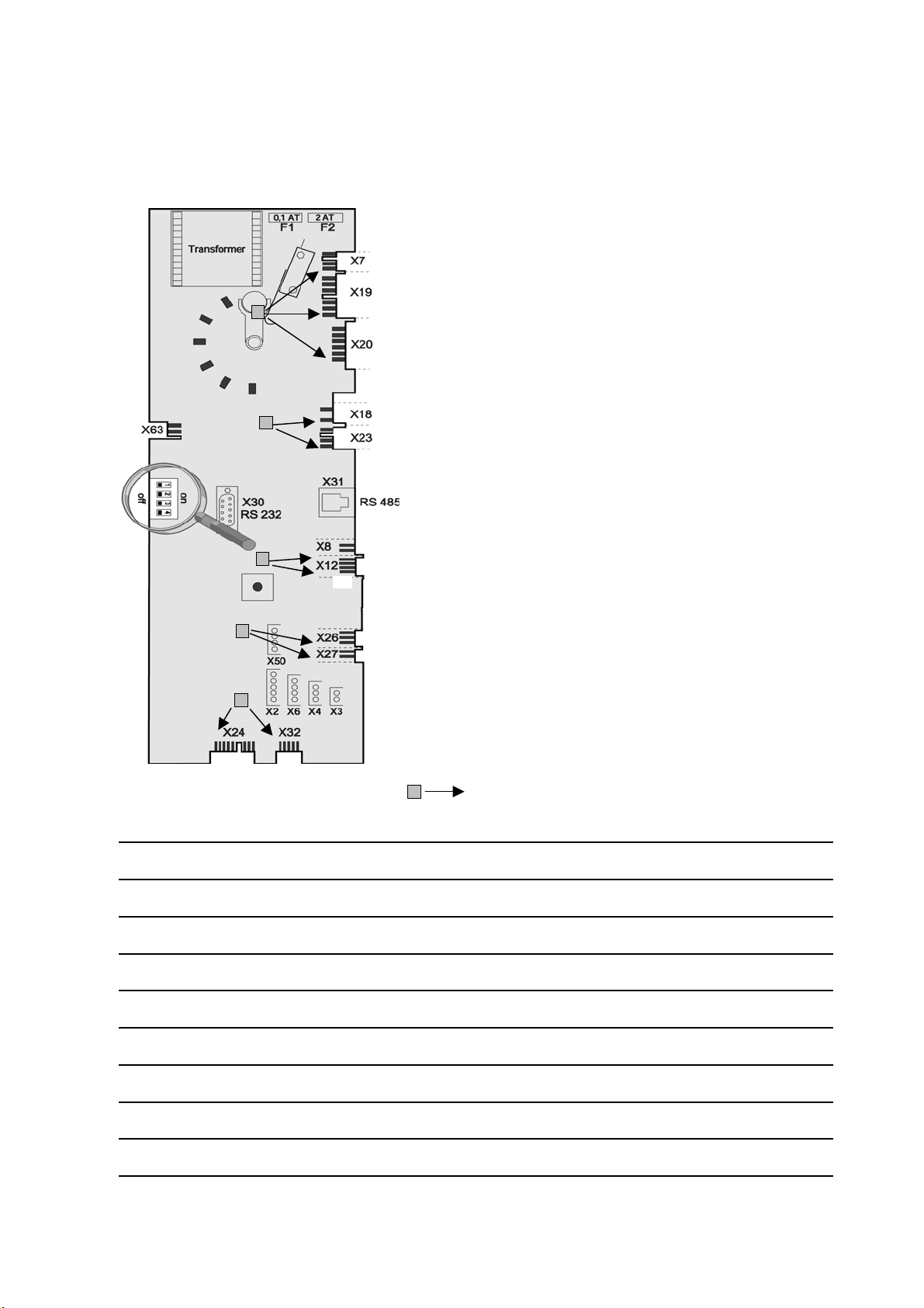
6. CM PCB I - 10
7. CM Sequence of events I - 11
8. CM Service level I - 16
9. CM Diagnostic I - 17
10. CM Running times I - 18
11. CM Basic settings I - 19
12. CM Function test I - 20
13. CM Failure code I - 21
14. CM Gas principle I - 22
15. CM Gas components I - 23
16. CM Change of gas type I - 24
17. CM Table Burner adjustment I - 27
18. CM Setting burner speed I - 28
Training Manual
Diagnostic and troubleshooting
SCC Line from 04-2004
Whenever working on any gas component like:
Gas valve, gas blower and / or changing connected type of gas
a detailed flue gas analysis MUST be done using
adequate CO and CO2measuring equipment!
This shall ONLY be done by trained technicians!
Always check appliance for possible gas leakages!
Isolate the appliance from mains supply
before opening the appliance
When working with chemicals, i.e. aggressive cleaning materials
always wear protective clothing,
goggles, face mask and gloves!
After maintenance / repair the appliance must be checked for electric
safety in accordance with your national, state and local requirements!

Part 2: Topic Page:
SCC Technique
1. SCC Overlay II - 01
2. SCC SelfCooking Control II - 02
3. SCC Combi Steamer mode II - 03
4. SCC Principle II - 04
5. SCC Operator PCB II - 05
6. SCC I/O PCB II - 06
7. SCC Sequence of events II - 07
8. SCC Service level II - 13
9. SCC Diagnostic mode overview II - 14
10. SCC Diagnostic mode II - 15
11. SCC Running times II - 17
12. SCC Basic settings overview II - 20
13. SCC Basic settings II - 21
14. SCC Function test overview II - 24
15. SCC Function test II - 25
16. SCC Service messages II - 27
17. SCC Calibration II - 29
18. SCC Drain valve II - 31
19. SCC Gas principle II - 32
20. SCC Gas technique II - 33
21. SCC Change type of gas II - 34
22. SCC Flue gas analysis II - 35
23. SCC Burner adjustments II - 37
Part 3: Common topics Page:
SCC and CM
1. Software flashing SCC III - 01
2. Software flashing CM III - 02
3. SCC LED code pcb III - 05
4. LED code fan motor SCC and CM III - 06
5. Descaler pump III - 07
8. Installation Checklist III - 09
9. Inspection list III - 13
10. Water Info III - 17

CM Technique from 04-2004
Steam
Hot Air
Combination
Low Temperature Steam
Finishing
Cool Down
Actual Temperature
Display
Timer button
Core Temperature button
Cabinet Temperature Dial
Time - Core Temperature
Display
Time - Core Temperature
Dial
I - 04

B1 Thermocouple interior cabinet
B2 Thermocouple quenching
B3 Thermocouple core temperature
B5 Thermocouple steam generator
F3 Safety thermostat
steam generator 160°C (320°F)
F4 Safety thermostat
interior cabinet 360°C (680°F)
Y1 Solenoid valve filing
Y2 Solenoid valve quenching
M1 Fan motor (without jumper)
M2 Fan motor Top (floor unit only)
with jumper
M4 SC-pump
S2 Level electrode
CM electric from 04-2004
I - 05

Level Control Steam Generator
Center S2 ==> Ground: 2 - 6V AC: water level too low
steam heating must switch OFF
solenoid valve filling ON
Center S2 ==> Ground: 0V AC: water level reached
steam heating can switch ON
solenoid filling switched OFF
Every 2 minutes steam elements will switch off for water level control
Notes:
PCB
VAC
I - 06

Steam Control CM from 04-2004
Intelligent steam control via quenching sensor
1. Filling of interior cabinet
based on time and
temperature control of B1
cabinet sensor
2. After steam saturation
inside cabinet steam will
also fill quenching
chamber
Notes:
3. Depending on the
temperature raise of
quenching sensor B2 the
duration of the next steam
supply is calculated
B2-1: Partial load
B2-2: Full load
4. Interval between steam
supply is depending on the
duration from energizing
steam elements until
reaching set quenching
temperature.
I - 07

1.
A)
B)
C)
D)
E)
F)
G)
H)
I)
2.
A)
B)
C)
D)
E)
F)
G)
3.
A)
B)
C)
D)
E)
F)
Select cleaning program
Cool down cabinet below 60°C
Spray inside cabinet with Rational cleaner
Key Code CM from 04-2004
Open cabinet door
Select "Cool Down"
Press core temperature key for 10 sec.
CLEN "CLEN" will show in cabinet temperature display
Press timer key 1x; Cleaning program starts automatically
(50min)
After end of program, leave cabinet door open over night
Rinse cabinet thoroughly with hand shower
Empty steam generator
(For checking of free drain after each installation and before disconnecting unit for longer period.)
Open cabinet door
Select "Cool Down"
Press core temperature key for 10 sec.
CLEN "CLEN" will show in cabinet temperature display
SC Select "SC" with temperature dial
Close water tap
Press timer key 1x and remain on "Cool Down" position for
about 45 sec.
Select descaling program
Open cabinet door
Select "Cool Down"
Press core temperature key for 10 sec.
CLEN "CLEN" will show in cabinet temperature display
CALC Select "CALC" with temperature dial
Press timer key 1x and follow procedure of the
decalcification instruction.
I - 08

Key Code CM from 04-2004
4.
A)
C)
D)
E)
Change temperature from °C - °F
Select any mode
100°C
212°F
Press timer and core temperature key simultaneously
for 10 sec. until ==>
Notes:
Display changes from °C to °F or vice versa
Release both keys
I - 09

X2 B3 Core temperature
X3 B1 Interior cabinet
X4 B2 Quenching / Steam control
X6 B5 Steam generator
X7 ON - OFF switch
X8 Buzzer
X12 Level electrode
X18 SC - pump
X19 Solenoid valves
X20 Energy optimising
X23 Vent hood
X24 SSR
X27 Door contact switch
X30 Serial interface
X31 BUS / RS 485 interface
X32 Timer / Core Potentiometer
X50 EEPROM
Counting sequence
Notes:
CM PCB - Connections
1
1
1
1
1
1
1
I - 10

1
2
3
4
5
6
7
8
9
Se
q
uence of events: CM electric
Mode: Low temperature steam
Temp. range 30-99°C (86-210°F)
Function Step Responsible sensor Signal Remark
Select vario steam mode
(Temp. setting 30-99°C (86-210°F))
Select time or core temperature
Close cabinet door Reed switch S3 Door open: 12VDC X27:(1-2)
Door closed: 0VDC X27:(1-2)
Check water level inside steam generator Level electrode S2 inside
Steam Generator
X12:(1-4) > 2VAC => no water
X12:(1-4) ~ 0VAC => water
Solenoid Y1 energizes when no
water, 230VAC, X19:(1-3)
Preheat steam generator 85°C (185°F);
SSR are energized
Thermocouple B5 inside
Steam Generator
SSR active: 12VDC X24:(1-2)+(5-6)
SSR not active: 0VDC X24:(1-2)+(5-6)
Heating elements de-energize
when B5 above 180°C (356°F)
Timer starts after successful preheating Logic on PCB Blinking dot in timer display
SSR active: 12VDC X24:(7-8)
SSR not active: 0VDC X24:(7-8)
Decision of Hot Air supply by PCB
logic
Steam supply until set temperature inside
cabinet is reached Cabinet sensor B1 SSR active: 12VDC X24:(1-2)+(5-6)
SSR not active: 0VDC X24:(1-2)+(5-6)
Hot Air supply (only 50%) when set
temperature can not be reached
in time by Steam alone
Cabinet sensor B1
Quenching (set to 70°C/158°F) Thermocouple B2 B2 above set Temp.: Y2 active
B2 below set Temp.: Y2 not active
Y2 active: 230VAC, X19:(2-4)
Y2 not active: 0VAC, X19:(2-4)
I - 11

1
2
3
4
5
6
7
8
9
Responsible sensor Remark
SSR active: 12VDC X24:(1-2)+(5-6)
SSR not active: 0VDC X24:(1-2)+(5-6)
B2 above set Temp.: Y2 active
B2 below set Temp.: Y2 not active
Quenching sensor B2
Hot Air supply (only 50%) when
set temperature (100°C/212°F)
can not be reached
Quenching (set to 70°C/158°F)
SSR active: 12VDC X24:(1-2)+(5-6)
SSR not active: 0VDC X24:(1-2)+(5-6)
SSR active: 12VDC X24:(7-8)
SSR not active: 0VDC X24:(7-8)
Cabinet sensor B1
Thermocouple B2
Door open: 12VDC X27:(1-2)
Door closed: 0VDC X27:(1-2)
X12:(1-4) > 2VAC => no water
X12:(1-4) ~ 0VAC => water
After reaching temperature steam
saturation is calculated by internal
logic via B1 and B2
Logic on PCB
Y2 active: 230VAC, X19:(2-4)
Y2 not active: 0VAC, X19:(2-4)
Solenoid Y1 energizes when no
water, 230VAC, X19:(1-3)
Heating elements de-energize
when B5 above 180°C (356°F)
Blinking dot in timer display
Reed switch S3
Level electrode S2 inside
Steam Generator
Se
q
uence of events: CM electric
Mode: Steam 100°C (212°F)
Temp. preset, not adjustable
Function Step
Select Steam mode
Select time or core temperature
Close cabinet door
Check water level inside steam generator
Steam supply up to steam saturation
inside cabinet
Preheat steam generator 85°C (185°F);
SSR are energized
Timer starts after successful preheating
Thermocouple B5 inside
Steam Generator
Signal
Decision of Hot Air supply by PCB
logic
I - 12

1
2
3
4
5
6
7
8
9Quenching (set to 70°C/158°F) Thermocouple B2 B2 above set Temp.: Y2 active
B2 below set Temp.: Y2 not active
Y2 active: 230VAC, X19:(2-4)
Y2 not active: 0VAC, X19:(2-4)
Steam supply up to steam saturation
inside cabinet Quenching sensor B2 SSR active: 12VDC X24:(1-2)+(5-6)
SSR not active: 0VDC X24:(1-2)+(5-6)
After reaching temperature steam
saturation is calculated by internal
logic via B1 and B2
Hot Air supply until set temperature inside
cabinet. Hot air has priority Cabinet sensor B1 SSR active: 12VDC X24:(7-8)+(3-4)
SSR not active: 0VDC X24:(7-8)+(3-4)
Timer starts after successful preheating Logic on PCB Blinking dot in timer display
Preheat steam generator 85°C (185°F);
SSR are energized
Thermocouple B5 inside
Steam Generator
SSR active: 12VDC X24:(1-2)+(5-6)
SSR not active: 0VDC X24:(1-2)+(5-6)
Heating elements de-energize
when B5 above 180°C (356°F)
Check water level inside steam generator Level electrode S2 inside
Steam Generator
X12:(1-4) > 2VAC => no water
X12:(1-4) ~ 0VAC => water
Solenoid Y1 energizes when no
water, 230VAC, X19:(1-3)
Close cabinet door Reed switch S3 Door open: 12VDC X27:(1-2)
Door closed: 0VDC X27:(1-2)
Mode: Combination
Temp. range 30-300°C (86-572°F)
Function Step Responsible sensor
Select time or core temperature
Select Combination mode
(Temp. 30-300°C (86-572°F))
Signal Remark
Se
q
uence of events: CM electric
I - 13

1
2
3
4
5
6
7
8
9Quenching (set to 70°C/158°F) Thermocouple B2 B2 above set Temp.: Y2 active
B2 below set Temp.: Y2 not active
Y2 active: 230VAC, X19:(2-4)
Y2 not active: 0VAC, X19:(2-4)
Hot Air supply (8 sec off - 8 sec. on) Cabinet sensor B1 SSR active: 12VDC X24:(7-8)+(3-4)
SSR not active: 0VDC X24:(7-8)+(3-4)
Decision of Hot Air supply by PCB
logic
Steam supply (8 sec on - 8 sec off) Quenching sensor B2 SSR active: 12VDC X24:(1-2)+(5-6)
SSR not active: 0VDC X24:(1-2)+(5-6)
After reaching temperature steam
saturation is calculated by internal
logic via B1 and B2
Timer starts after successful preheating Logic on PCB Blinking dot in timer display
Preheat steam generator 85°C (185°F);
SSR are energized
Thermocouple B5 inside
Steam Generator
SSR active: 12VDC X24:(1-2)+(5-6)
SSR not active: 0VDC X24:(1-2)+(5-6)
Heating elements de-energize
when B5 above 180°C (356°F)
Check water level inside steam generator Level electrode S2 inside
Steam Generator
X12:(1-4) > 2VAC => no water
X12:(1-4) ~ 0VAC => water
Mode: Finishing
Temp. range 30-300°C (86-572°F)
Function Step Responsible sensor Signal
Select Finishing
(Recom. Temp. 100-140°C (212-284°F))
Select time or core temperature
Close cabinet door Reed switch S3 Door open: 12VDC X27:(1-2)
Door closed: 0VDC X27:(1-2)
Se
q
uence of events: CM electric
Remark
Solenoid Y1 energizes when no
water, 230VAC, X19:(1-3)
NOTE: For initial heating of cabinet => alternately energy supply of Steam and Hot Air (8 seconds each)
I - 14

1
2
3
4
5
6
Se
q
uence of events: CM electric
Quenching (set to 90°C/194°F) Thermocouple B2 B2 above set Temp.: Y2 active
B2 below set Temp.: Y2 not active
Hot Air supply until set temperature inside
cabinet is reached
Timer starts at once Logic on PCB Blinking dot in timer display
Close cabinet door Reed switch S3 Door open: 12VDC X27:(1-2)
Door closed: 0VDC X27:(1-2)
Select time or core temperature
Select Hot Air
(Temp. 30-300°C (86-572°F))
Function Step Responsible sensor Signal Remark
Mode: Hot Air
Temp. range 30-300°C (86-572°F)
Y2 active: 230VAC, X19:(2-4)
Y2 not active: 0VAC, X19:(2-4)
Cabinet sensor B1 SSR active: 12VDC X24:(7-8)+(3-4)
SSR not active: 0VDC X24:(7-8)+(3-4)
I - 15

A)
B)
C) Select service package with timer dial
D)
E)
F)
G)
A)
B)
C)
D) Select desired step of function test with timer dial
E)
F)
G)
Notes:
Starting with software version C1-06-03 gas related information will be shown on gas units only!
To de-activate function test set DIP switch 3 to "OFF" position.
Switch unit ON
Get access for activate selected step by pressing timer key
Activate selected step with core temperature key
F1 First step of function test is displayed
On operator PCB set DIP switch 3 to "ON" position
To de-activate service package set DIP switch 1 to "OFF"
position.
Function Test
Service Level CM from 04-2004
Switch unit ON
Activate selected step with the temperature key
On operator PCB set DIP switch 1 to "ON" position
Diagnostic Program
Running times
dP
Select with the timer dial the desired step inside the package
Basic settings
rt
SE
Activate with the core temperature key the desired service package
I - 16

dP # Connection
dP 1
dP 2 X 3
Reset by pressing
for 5 sec.
dP 3 X 4
Reset by pressing
for 5 sec.
dP 4 X 2
Reset by pressing
for 5 sec.
dP 5 X 6
Reset by pressing
for 5 sec.
dP 6
Reset by pressing
for 5 sec.
dP 7 X27:(1-2)
dP 8
X12:(1-4) S2
X19:(1-2) Y1
dP 9
dP 10
dP 11 BUS / RS485
dP 12 BUS / RS485
dP 13 X 20
dP 14 X 26
dP 15
dP 16 from version 01-06-03
dP 17 from version 01-06-03
Notes:
Flame Current Steam x.x µA
Flame Current Hot Air Top x.x µA
Bottom x.x
µA
max value
0 - 1 - 2
1 - 0
Software
version:
05.00
max value
max value
max value
max value
1 - 0
Y1
1 - 0
Service Level: dP -- Diagnostic
Description
Cabinet
display
Timer
display
1 - 0Energy pulsing
Unit size and type 61 - 202 ELE - GAS
0 - 1 - 2
B5 Steam generator sensor actual value
PCB temperature actual value
S3 Door contact
S2 Water level steam
generator
S2
1 - 0
Actual rpm
Actual rpm
Speed fan motor bottom Set rpm
Speed fan motor top Set rpm
Software version
Software
version:
C - 1 -
B1 Cabinet sensor actual value
Energy optimising input
B2 Quenching sensor actual value
B3 Core sensor actual value
Hot Air elements
0 - off; 1 - 50%; 2 - 100% Temp B1
Steam elements
0 - off; 1 - 50%; 2 - 100% Temp B5
I - 17

rt 1 number
rt 2 min
rt 3 min
rt 4 min
rt 5 hrs
rt 6 hrs
rt 7 hrs
rt 8 hrs
rt 9 hrs
rt 10 hrs
rt 11 hrs
rt 12 hrs
rt 13 hrs
Notes:
Total time cleaning program Can not be reseted
Total time hot air mode Can not be reseted
Total time finishing mode Can not be reseted
Total time combination mode Can not be reseted
Total time vario steam mode Can not be reseted
Total time hot air heating time
Reset by pressing
for 5 sec.
Total time steam mode Can not be reseted
Total time Y2 valve quenching
Reset by pressing
for 5 sec.
Total time steam heating time
Reset by pressing
for 5 sec.
Timer display: 1-999
Temp. display: >1000
Total running time unit Can not be reseted
Service Level: rt -- Running Times
Total S3 door openings
Reset by pressing
for 5 sec.
Total time M4 SC-pump
Reset by pressing
for 5 sec.
Total time Y1 valve filling
Reset by pressing
for 5 sec.
I - 18

A) SE1
B)
SE1
SE2
SE3
SE4 SC
SE5 SHO
SE6
SE 7
SE 8
since C1-
06-04
SE 9, 10, 11
SE 12,13, 14
SE 15,16, 17
Press time key and adjust displayed rpm with timer dial
SE15 = MIN rpm; SE16 = Start rpm; SE17 = MAX rpm
Always check CO2values in function test
Press time key and select "on" or "oFF" in with timer dial
Press time key and select new gas type with timer dial
NOTE: C02values must be manually controlled/adjusted in function test
Corresponding gas blower speed is automatically adjusted
Press time key and select "ST" for steam, "HA1" for hot air top or
"HA2" for hot air bottom (only 201/202) with timer dial;
Average lenght in mm of CO2crew on gas valve is shown in timer display
Adjusting speed of blower motor hot air, bottom (+ / -10%)
(After blower speed adjustment indicated gas type (SE6) gets suffix "-S")
Press time key and adjust displayed rpm with timer dial
SE9 = MIN rpm; SE10 = Start rpm; SE11 = MAX rpm
Always check CO2values in function test
Adjusting speed of blower motor steam (+/ -10%)
(After blower speed adjustment indicated gas type (SE6) gets suffix "-S")
Adjusting speed of blower motor hott air, top (+ / -10%)
(After blower speed adjustment indicated gas type (SE6) gets suffix "-S")
Adjustment of installation altitude above sea level
0-500m (0-1640ft), 500-1000m (1640-3280ft),
1000-1500m (3280-4920ft), 1500-2000m (4920-6560ft)
2000-2500m (6560-8200ft), 2500-3000m (8200-9840ft)
Press time key and select installaton altitude in 500m steps. Temperature
and timer display are blinking. Confirm altitude setting with core
temperature key.
Press time key and adjust displayed rpm with timer dial
SE12 = MIN rpm; SE13 = Start rpm; SE14 = MAX rpm
Always check CO2values in function test
Steam heating time since last SC-Automatic
Preset Steam heating time until SC-Automatic
(default 45min, 20-120 min adjustable)
Setting new gas type (G20, G25, G30, G31, 13A, (ref. SE9-17)
Presetting of CO2screw on gas valve after gas type modification.
Show mode (on - oFF)
Press time key and adjust preset steam heating time from 20 - 120 minutes
with timer dial
Flushing time SC-Automatik
(default 45 seconds)
Press time key and adjust flushing time of SC-automatik from 30 - 90
seconds with timer dial
Press time key and select "on" or "oFF" in with timer dial
Operation steam generator pump
(continous or pulsing mode)
Activate selected step with timer key
Press time and core key for 5 seconds to set steam heating time to preset
steam heating time plus 1 minute
Service Level: SE -- Basic settings
SE Basic settings
Select desired step with timer dial
(
fan motor and heatin
g
elements are automaticall
y
OFF
)
I - 19

F # Function Connection
Cabinet
display
Timer
display Comment
F1 Steam 50% Electric unit X24:(1-2)
actual temp.
B5 steam generator 1 / 0 Gas: No function
F2 Steam 100% Electric unit X24:(1-2)+(5-6)
actual temp.
B5 steam generator 1 / 0 Gas: Steam Burner
F3 Hot Air 50% Electric unit X24:(7-8)
actual temp.
B1 cabinet 1 / 0 Gas: HA burner top
F4 Hot Air 100% Electric unit X24:(7-8)+(3-4)
actual temp.
B1 cabinet 1 / 0 Gas: HA burner bottom
F5 Steam, Gas unit BUS / RS485
actual temp.
B5 steam generator 100 / 0
F6 Hot Air Top, Gas unit BUS / RS485
actual temp.
B1 cabinet 100 / 0
F7 Hot Air Bottom, Gas unit BUS / RS485
actual temp.
B1 cabinet 100 / 0
F8 Top Motor MAX speed BUS / RS485 Set rpm Actual rpm
F9 Top Motor MIN speed BUS / RS485 Set rpm Actual rpm
F10 Bottom Motor MAX speed BUS / RS485 Set rpm Actual rpm
F11 Bottom Motor MIN speed BUS / RS485 Set rpm Actual rpm
F12 Solenoid valve quenching X19:(2-4)
actual temp.
B2 quenching
Y2
1 / 0
F13 Solenoid valve filling X19:(1-3)
Level electrode S2
1 / 0
Y1
1 / 0
F14 Steam generator pump
X18:(1-2) M4
X12:(1-4) S2
Level electrode S2
1 / 0
M4
1 / 0
F15 Buzzer X8:(1-2) 1 / 0
F16 All Displays
F17 Vent hood X 23
F18
F19
Blower motor steam
MIN rpm BUS / RS485 Actual rpm Set CO2value Check CO2value only
F20
Blower motor steam
Start rpm BUS / RS485 Actual rpm Set CO2value
F21
Blower motor steam
MAX rpm BUS / RS485 Actual rpm Set CO2value
Adjust CO2value with
CO2screw on gas valve
F22
Hot air blower motor, top
MIN rpm BUS / RS485 Actual rpm Set CO2value Check CO2value only
F23
Hot air blower motor, top
Start rpm BUS / RS485 Actual rpm Set CO2value
F24
Hot air blower motor, top
MAX rpm BUS / RS485 Actual rpm Set CO2value
Adjust CO2value with
CO2screw on gas valve
F25
Hot air blower motor, bottom
MIN rpm BUS / RS485 Actual rpm Set CO2value Check CO2value only
F26
Hot air blower motor, bottom
Start rpm BUS / RS485 Actual rpm Set CO2value
F27
Hot air blower motor, bottom
MAX rpm BUS / RS485 Actual rpm Set CO2value
Adjust CO2value with
CO2screw on gas valve
Service Level: F -- Function Test
NOTE: In Function test components are NOT protected against overload!
I - 20
Table of contents