BEGA Gantenbrink-Leuchten KG · Postfach 31 60 · 58689 Menden · info@bega.com · www.bega.com
2/3
Sicherheit
Für die Installation und für den Betrieb
dieser Leuchte sind die nationalen
Sicherheitsvorschriften zu beachten.
Die Montage und Inbetriebnahme darf nur
durch eine elektrotechnische Fachkraft
erfolgen.
Der Hersteller übernimmt keine Haftung für
Schäden, die durch unsachgemäßen Einsatz
oder Montage entstehen.
Werden nachträglich Änderungen an der
Leuchte vorgenommen, so gilt derjenige als
Hersteller, der diese Änderungen vornimmt.
Safety indices
The installation and operation of this luminaire
are subject to national safety regulations.
Installation and commissioning may only be
carried out by a qualied electrician.
The manufacturer is then discharged from
liability when damage is caused by improper
use or installation.
If any luminaire is subsequently modied, the
persons responsible for the modication shall
be considered as manufacturer.
Sécurité
Pour l’installation et l’utilisation de ce luminaire,
respecter les normes de sécurité nationales.
L’installation et la mise en service ne doivent
être effectuées que par un électricien agréé.
Le fabricant décline toute responsabilité
résultant d’une mise en œuvre ou d’une
installation inappropriée du produit.
Toutes les modications apportées au luminaire
se feront sous la responsabilité exclusive de
celui qui les effectuera.
Montage
Die Befestigung der Leuchte erfolgt
wahlweise mit Erdstück 71 091 oder mit
Befestigungssockel 71 092 zum Aufschrauben
auf ein Fundament.
Für den elektrischen Anschluss der Leuchte ist
eine Kabellänge von ca. 1,5 m über Oberkante
Bodenbelag ausreichend.
Der Fußpunkt der Leuchte darf nicht tiefer als
Oberkante Bodenbelag liegen.
Es ist darauf zu achten, dass die rechteckige
Flanschplatte in die gewünschte Leuchten-
position ausgerichtet wird und das Rohr
absolut senkrecht steht.
Die Schutzschicht im Bereich des Erdstückes
darf nicht beschädigt werden.
Installation
The installation of the luminaire can optionally
be done with an anchorage unit 71 091 or
mounting base 71 092 for bolting onto a
foundation.
A cable length of approx. 1.5 m above top
edge of the mounting surface is sufcient for
the electrical connection of the luminaire.
The base of the luminaire must not be below
top edge of the mounting surface.
Note that the rectangular ange plate is aligned
with the desired luminaire position and that the
tube is absolutely vertical.
The protective coating at the anchorage unit
must not be damaged.
Installation
La xation du luminaire est effectuée au choix
sur pièce enterrée 71 091 ou sur socle de
xation 71 092 pour xation par vis sur un
massif de fondation.
Pour le raccordement électrique du luminaire
une longueur de câble d'environ 1,5 m
au-dessus de la couche de nition du sol est
nécessaire.
Le bas du luminaire ne doit pas se trouver en
dessous de la couche de nition du sol.
Lors de l'installation de la pièce enterrée il
faut bien vérier que la asque rectangulaire
de xation soit positionnée conformément à
l'orientation souhaitée du luminaire et que le
tube soit absolument en position verticale.
La couche protectrice de la pièce à enterrer ne
doit pas être endommagée.
50 ×
150
250
befestigte Oberfläche
Paved surface
Surface consolidée
verdichteter Boden
Compacted soil
Sol damé
Erdreich · Soil · Terre
Sauberkeitsschicht
Sub-base
Couche d’assainissement
Drainage
Beton · Concrete · Béton
310310
390390
10001000
900900
210210
1400 × 14001400 × 1400
6 × 190 Nm
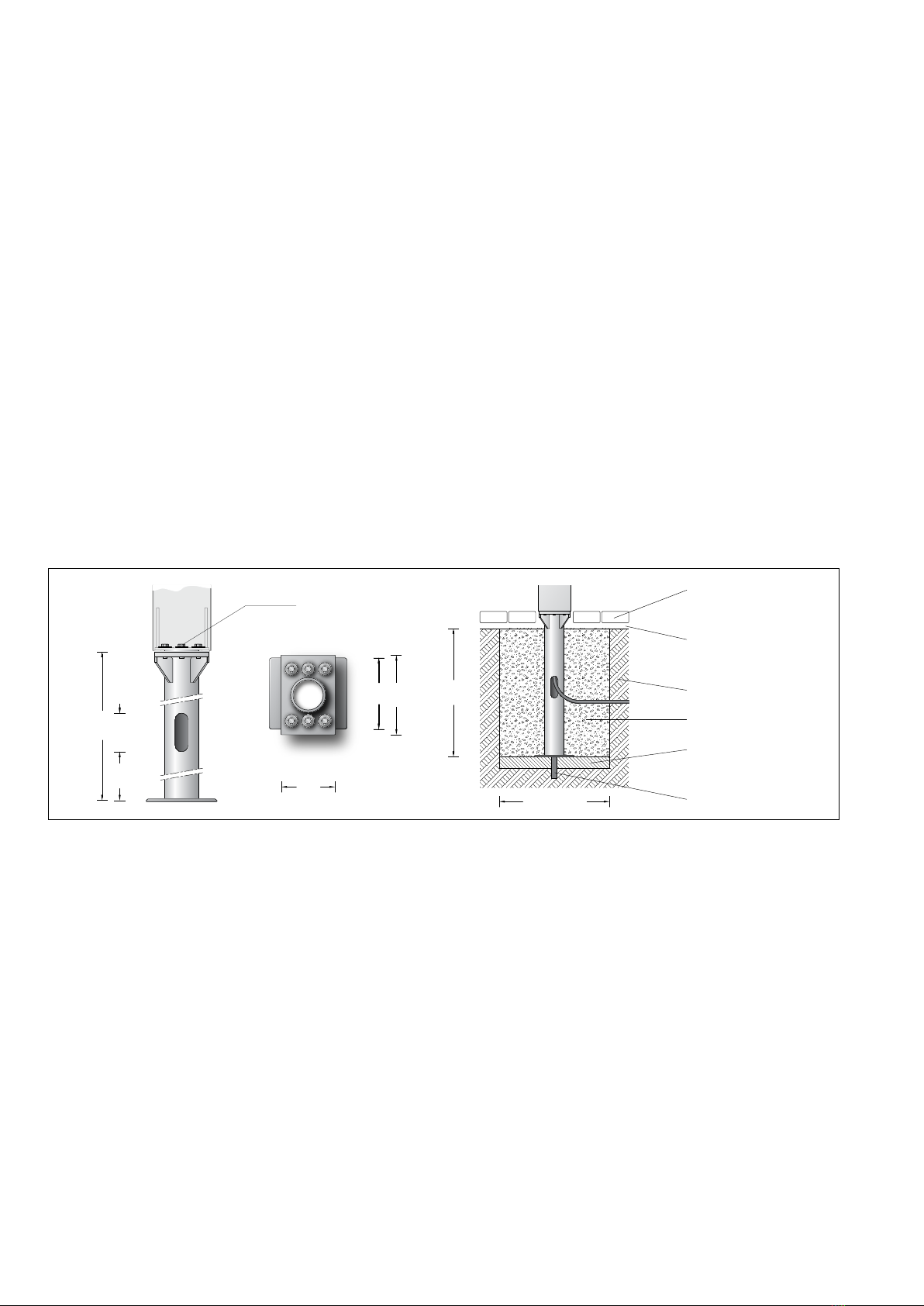
Montage Erdstück
Die Fundamentgröße ist abhängig von der
Topographie, Bodenbeschaffenheit und
Windbelastung und muss jeweils bauseits
bestimmt werden.
Dazu gilt die Norm DIN 1045.
Die obige beispielhafte Fundamentempfehlung
gilt nur für einen tragfähigen Baugrund und nur
für das Lichtbauelement 84 688.
Zweiteilige Grundplatte aus dem Erdstück
entnehmen und am Erdstück befestigen.
Erdkabel durch seitliche Leitungseinführung in
das Erdstück einführen.
Erdstück standsicher einbauen.
Installation anchorage unit
The size of the foundation depends on the
topography, condition of the soil and the wind
load and must be determined on site.
DIN1045 applies.
The above exemplary recommendation for
a foundation is only applicable for a stable
subgrade and the light building element 84 688.
Remove the two-part anchor plate from the
anchorage unit and x it at the anchorage unit.
Lead the mains supply cable through the lateral
cable entry into the anchorage unit.
Install anchorage unit stably.
Installation pièce à enterrée
Le volume et les dimensions du massif béton
dépendent de la topographie, de la pression
à fond de fouille du sol, de la zone de vent,
ainsi que des forces et des charges exercées
et doivent être individuellement dénis sur le
chantier.
La norme DIN1045 est alors applicable.
Le massif de fondation recommandé ci-dessus
est un exemple uniquement valable pour
un terrain à bâtir compact, et pour le prolé
lumineux 84 688.
Retirer de la pièce enterrée la plaque de
stabilisation composée de deux pièces.
Fixer la sur la pièce à enterrer. Introduire le
câble réseau dans la pièce à travers l’entrée de
câble latérale.
Installer et stabiliser la pièce à enterrer.


