Beissbarth MS 65 OR RAC S80 User manual

MS 65 OR RAC S80
en
Original instructions
Tyre Changer
zh
使用说明书
拆胎机


1 697 630 500 2013-03-05|Beissbarth GmbH
| MS 65 OR RAC S80 | 3
Contents 4
中文内容 21

1 697 630 500 2013-03-05
| Beissbarth GmbH
4 | MS 65 OR RAC S80 |en
Contents
1. Symbols used 5
1.1 In the documentation 5
1.1.1 Warning notices -
Structure and meaning 5
1.1.2 Symbols in this documentation 5
1.2 On the product 5
2. User information 6
2.1 Important notes 6
2.2 Safety instructions 6
2.3 Electromagnetic compatibility (EMC) 6
3. Product description 6
3.1 Designated use 6
3.2 Requirements 6
3.3 Delivery specification 6
3.4 Special accessories 6
3.5 Description of unit 7
3.6 Description of function 7
4. Initial commissioning 8
4.1 Unpacking 8
4.2 Assembly 8
4.2.1 Cover removal 8
4.2.2 Lifting of the tilting column 8
4.2.3 Column fixing 8
4.2.4 Put in place the vertical rod 9
4.2.5 Mounting of the bead breaking cylinder 9
4.2.6 Machine positioning 9
4.3 Pneumatic connection 11
4.4 Electrical connection 12
4.5 Check rotation direction 12
5. Operating instructions 13
5.1 Moving jaws adjustment 13
5.2 Tire demounting 14
5.2.1 Preparations for demounting 14
5.2.2 Demounting 14
5.3 Tire mounting 15
5.3.1 Mounting preparations 15
5.3.2 Mounting 15
5.4 Inflation 16
5.4.1 Inflation with inflation gun 16
5.5 Functioning anomalies 17
6. Maintenance 18
6.1 Suggested lube 18
6.2 Cleaning and servicing 18
6.2.1 Maintenance intervals 18
6.2.2 Condensate removal 18
6.2.3 Nebulizer oil refill 18
6.2.4 Change oil in the oil nebulizer 18
7. Decommissioning 19
7.1 Place change 19
7.2 Temporary decommissioning 19
7.3 Disposal 19
8. Technical data 19
8.1 MS 65 OR RAC S80 19
8.2 Dimensions and weights 19
8.3 Reach 19
8.3.1 Car wheels 19
8.3.2 Motorcycle wheels 19
9. Glossary 20
1 697 630 500 2013-03-05
|
Beissbarth GmbH
Symbols used | MS 65 OR RAC S80 | 5 en
1. Symbols used
1.1 In the documentation
1.1.1 Warning notices - Structure and meaning
Warning notices warn of dangers to the user or people
in the vicinity. Warning notices also indicate the con-
sequences of the hazard as well as preventive action.
Warning notices have the following structure:
KEY WORD – Nature and source of hazard!
Consequences of hazard in the event of
failure to observe action and information
given.
¶Hazard prevention action and information.
The key word indicates the likelihood of occurrence and
the severity of the hazard in the event of non-observance:
Signal
word
Probability of
occurrence
Severity of danger if in-
structions not observed
DANGER Immediate impend-
ing danger
Death or severe injury
WARNING Possible impending
danger
Death or severe injury
CAUTION Possible dangerous
situation
Minor injury
1.1.2 Symbols in this documentation
Sym-
bol
Designation Explanation
!Attention Warns about possible property damage.
iInformation Practical hints and other
useful information.
1.
2.
Multi-step
operation
Instruction consisting of several steps
eOne-step
operation
Instruction consisting of one step.
Intermediate
result
An instruction produces a visible inter-
mediate result.
"Final result There is a visible final result on comple-
tion of the instruction.
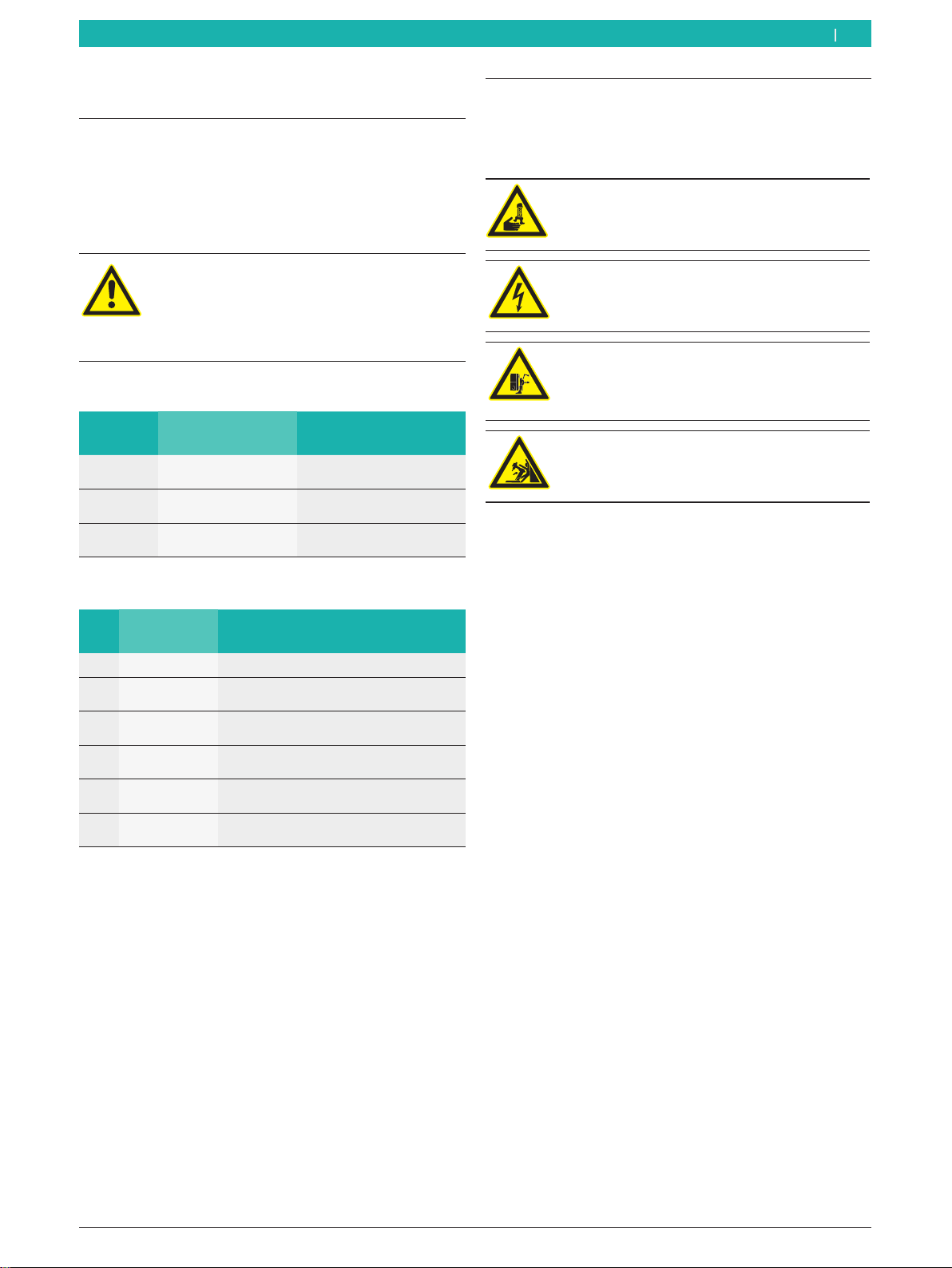
Mounting tool
Danger of crushing the fingers between the
mounting tool and the rim.
Mains tension
Danger of electrical shock when touching the
parts of the electrical system.
Bead breaker
Danger of crushing the limbs between the
bead breaker and the tire.
Column tilting
Danger of crushing in the area close to the
tilting column.
1.2 On the product
!Observe all warning notices on products and ensure
they remain legible!

1 697 630 500 2013-03-05
| Beissbarth GmbH
6 | MS 65 OR RAC S80 | User informationen
2. User information
2.1 Important notes
Important information on copyright, liability and warran-
ty provisions, as well as on equipment users and compa-
ny obligations, can be found in the separate manual "Im-
portant notes on and safety instructions for Beissbarth
Tire Equipment". These instructions must be carefully
studied prior to start-up, connection and operation of
the MS 65 OR RAC S80 and must always be heeded.
2.2 Safety instructions
All the pertinent safety instructions can be found in the
separate manual "Important notes on and safety instruc-
tions for Beissbarth Tire Equipment". These instructions
must be carefully studied prior to start-up, connection
and operation of the MS 65 OR RAC S80 and must al-
ways be heeded.
2.3 Electromagnetic compatibility (EMC)
The MS 65 OR RAC S80 is a class A product as per
2004/108/EG.
3. Product description
3.1 Designated use
MS 65 OR RAC S80 is a modern tire changer for moun-
ting and demounting of car and motorcycle tires.
iMS 65 OR RAC S80 has to be used exclusively for the
specified purpose and only in the functioning scope
shown in these instructions. Any other use different
from that specified has to be considered improper
and therefore not allowed.
iThe manufacturer is not liable for any damage cau-
sed by improper use.
3.2 Requirements
MS 65 OR RAC S80 has to be installed on an even sur-
face made of concrete or similar materials, and has to
be firmly anchored. A pneumatic connection is reque-
sted.
3.3 Delivery specification
Denomination Order code
MS 65 OR RAC S80
Bead lifting lever 1 695 105 190
Brush 1 695 100 123
Inflation gun with manometer 1 697 630 100
Rubber inflation pipe 1 697 630 099
Protection tab 1 695 100 798
Lane protection set for 19" wedge 1 695 104 071
Mounting tool cover 1 695 102 725
3.4 Special accessories
Denomination Order code
8" connections device (4 pieces) 1 695 103 542
Special 17-21" connections device (4 pie-
ces)
1 695 103 543
Motorbike wheel connection device 1 695 103 543
Bead breaker protection 1 695 102 090
Bead locking clamp 1 695 103 302
Lower wedge 1 695 103 261
Upper wedge 1 695 103 216
Tubeless inflation kit 1 695 103 858

1 697 630 500 2013-03-05
|
Beissbarth GmbH
Product description | MS 65 OR RAC S80 | 7 en
3.6 Description of function
Below are reported the main functions of the listed
components of the MS 65 OR RAC S80:
RPedal box, comprehends control pedals of the
equipment (locking flange rotation pedal, bead brea-
king pedal, locking jaws pedal, tilting column pedal).
RBead breaker, for bead breaking of tires from the
rim; it is made of the bead breaking arm pneuma-
tically operated by a double effect cylinder (fitted
with a special device with three positions which, by
letting the blade open more widely, allows also bead
breaking of particularly wide tires), an arm positio-
ning lever, antiabrasive supports for rim support
during bead breaking phases.
RColumn assembly, made of a tilting column with
2 operating positions (which allows demounting
and mounting of tires on rims of remarkable width)
which holds the components needed to demount
(and mount) the tire from the rim: horizontal sliding
arm (with mounting lever), vertical sliding rod (with
locking knob), mounting tool for demounting (and
mounting) the tire from the rim with the help of the
bead lifting lever.
RLocking plate, locking and rotation device (clockwise
and counterclockwise) of the rim, pneumatically
driven by 2 cylinders, made of 4 movable sliders
(adjustable for use also with wheels up to 26'') with
locking jaws for the internal and external locking of
the rim.
3.5 Description of unit
On the MS 65 OR RAC S80 there are rotating
and moving parts that could injure fingers
and arms.
2
4
3
1
5
7
8
13
12
14
15
18
17
16
6
20
9
10
21
19
652099-01_Mi
11
22
Fig. 1: MS 65 OR RAC S80
Pos. Name Function
1Locking flange rotation pedal Locking plate rotation:
Rclockwise (press down the pedal)
Rcounter-clockwise (lift the pedal from bottom to top)
2 Bead breaker pedal Bead breaking arm activation.
3 Locking jaw pedal Opening and closing of the locking plate jaws.
4 Tilting column pedal Tilting column activation.
5 Bead breaking arm Bead breaking of the tire from the rim.
6 Bead breaking arm lever Bead breaking arm activation.
7 Bead breaker blade Bead breaking.
8 Antiabrasive supports Tire support for bead breaking operations.
9 Tilting column Sliding arm and mounting tool support .
10 Horizontal sliding arm Horizontal positioning of the mounting tool.
11 Locking lever Tire locking of the horizontal sliding arm.
12 Vertical sliding rod Vertical positioning of the mounting tool.
13 Vertical rod locking lever Tire locking of the vertically sliding rod. Operating on the knob it is possible to achieve a 3 mm
spacing (adjustable) from the edge of the rim.
14 Mounting tool Mounting and demounting of the tire from the rim (with the help of the bead lifting lever).
15 Sliding roller To be inserted in the mounting tool BOX, to avoid any kind of friction between the rim and the mounting
tool during tire mounting and demounting phases. For the alloy rims a special "tab" is arranged.
16 Locking plate Locking and rotation of the rim.
17 Movable lanes Positioning of the locking jaws.
18 Locking jaws Internal or external locking of the rim.
19 Grease cup holding ring Mounting paste containing support.
20 Bead lifting lever Lifting of the tire edge in demounting and mounting phases.
21 Speed switch Passing from the first to the second speed.
22 2 position column switch Operation of the 2 position column (lifting and lowering).

1 697 630 500 2013-03-05
| Beissbarth GmbH
8 | MS 65 OR RAC S80 | Initial commissioningen
4. Initial commissioning
4.1 Unpacking
1. Remove the iron tape and the fixing clamps from the
pallet and the packaging cardboard.
iAfter unpacking check the integrity of
MS 65 OR RAC S80 and check that no components
are visibly damaged. In case of doubt do not proceed
to start-up and contact a qualified technician and/or
your vendor.
2. Take out of the transport crate the standard accesso-
ries and the packaging materials.
iDispose correctly of packaging material, hand it over
to the designated collection points.
4.2 Assembly
4.2.1 Cover removal
1. Unscrew the 4 screws of the side cover and remove
the cover itself.
4.2.2 Lifting of the tilting column
1. Unscrew the fulcrum-pin screw of the column with
the hex key 6 and remove the pin.
652012-02_Mi
2. Get a 1 Mt lifting sling, DR 50 model (safety factor
6:1); wrap the sling around the tilting column (1),
extend the bead breaking arm and lift the column
with a hoist (2).
652012-03_Mi
1
2
3. Remove the external elastic ring with appropriate
pliers and take off the pin.
652012-04_Mi
4.2.3 Column fixing
1. Align the cylinder rod and the tie rod holes.
652012-05_Mi
2. Insert the air tube in the slot in the machine box.
3. Fix the column to the cylinder tank by inserting
the pin with a hammer and tighten the fulcrum-pin
screw.
652012-07_Mi
1 697 630 500 2013-03-05
|
Beissbarth GmbH
Initial commissioning | MS 65 OR RAC S80 | 9 en
4. Insert again the pin passing through the cylinder
rod and tie rod holes; put back in place the external
elastic ring.
652012-08_Mi
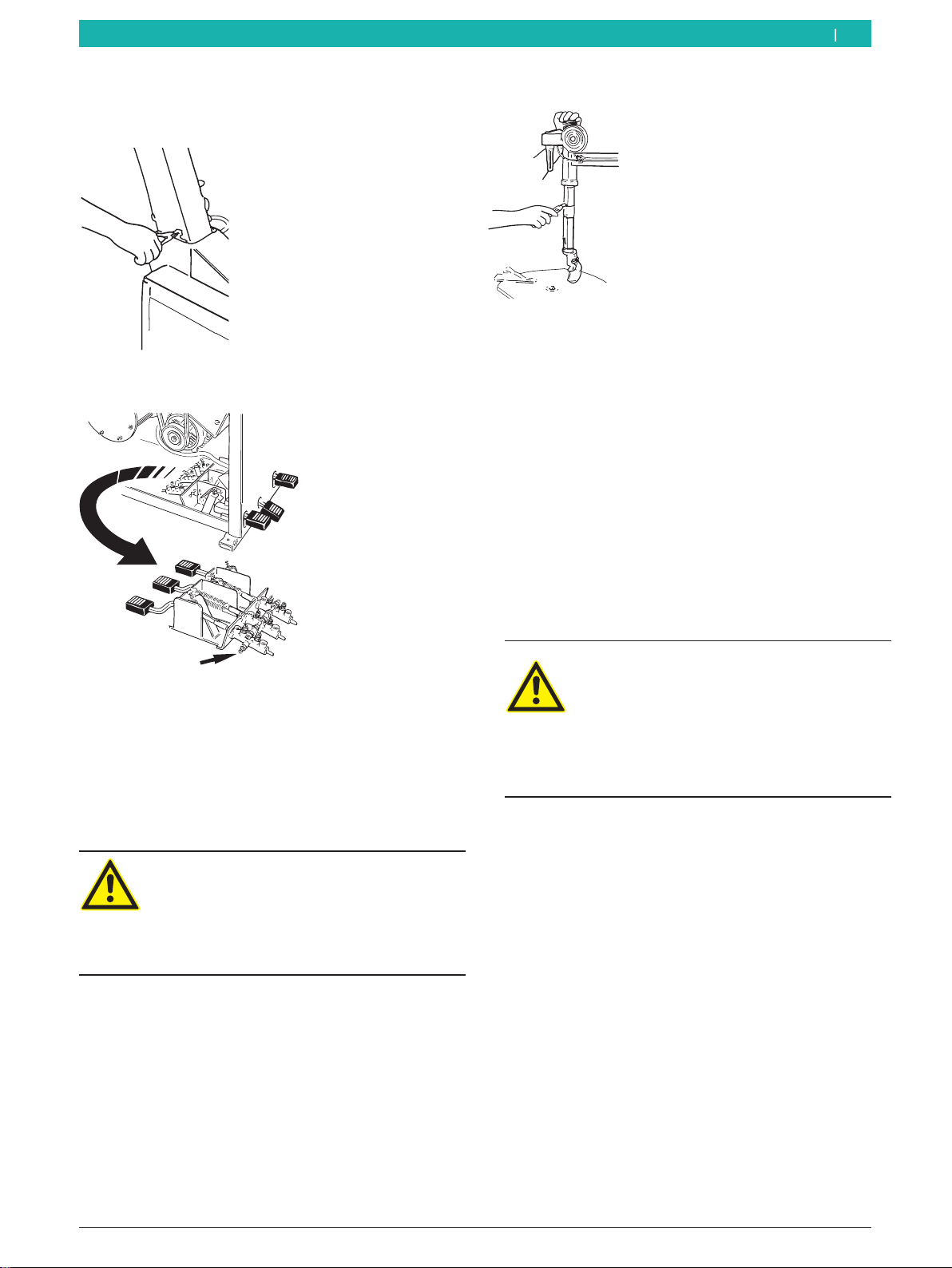
5. Connect the pneumatic lock supply pipe on the
pedal box joint.
652012-10_Mi
1
4.2.4 Put in place the vertical rod
1. Put a hand down on the protection cap (placed on
top of the rod) and press it downwards; with the
other hand remove the steel rod inserted between
the arm and the mounting tool; take off slowly the
hand that was pressing the rod protection cap.
Danger!
The spring could eject violently the rod from
its housing, thus it might be a serious danger
for the operator.
¶Be careful when carrying out this operati-
on.
2. Remove the adhesive tape with a cutter.
652012-09_Mi
4.2.5 Mounting of the bead breaking cylinder
1. Remove the external elastic ring and take off the
hinge rod from its housing in the bead breaking arm.
2. Disconnect the fixing grain of the fixing bush with
hex key, rotate and unblock the fixing bush to
remove pressure from the spring, remove the fixing
pin and remove the adjusting bush from the bead
breaking cylinder rod .
3. Insert the bead breaking arm and centre the joint pin
with the cylinder rod, ensuring that the flat part of
the joint pin is facing the outside.
4. Insert the hinge-pin and put back in place the exter-
nal elastic ring.
5. Place the buffer spring on the provided tab
6. Remount the adjusting bush.
Danger!
Wrong mounting of the bead breaking cylin-
der compromises machine functioning and
can be a serious danger for the operator.
¶During machine installation be sure that
the nut is correctly screwed in the bead
breaking cylinder rod (at least 10 mm).
4.2.6 Machine positioning
1. Put back in place the side door.
2. Loosen the two screws that fix MS 65 OR RAC S80
to the pallet.

1 697 630 500 2013-03-05
| Beissbarth GmbH
10 | MS 65 OR RAC S80 | Initial commissioningen
652012-12_Mi
Warning - damage risk!
The lifting belts can crush the flexible supply
pipes of the cylinder or damage the applied
parts of the MS 65 OR RAC S80.
¶Insert the lifting belts carefully.
3. Remove the back protection of the locking lever, as
shown.
4. Insert the appropriate lifting belts (length belt 1: 1
Mt, belt 2: 3 Mt), with sufficient capacity, as shown.
652013-02_Mi
2
1
!
Warning - tilting danger!
The barycentre of the MS 65 OR RAC S80
does not lie in its centre.
¶It is necessary to lift the machine slowly.
5. Lift the MS 65 OR RAC S80 with a lift crane and in-
stall it in the designed area respecting the minimum
distances as shown in the picture.
652016-03_Mi
500 850
1990
950 500
iFor safe and ergonomic use of the
MS 65 OR RAC S80 it is recommended to leave a mi-
nimum of 500 mm space from the surrounding walls.

1 697 630 500 2013-03-05
|
Beissbarth GmbH
Initial commissioning | MS 65 OR RAC S80 | 11 en
Warning - tilting danger!
During tire inflation considerable forces are
exerted.
¶The MS 65 OR RAC S80 has to be fixed in
at least 3 points on the floor (screw holes
see chap. 4.2)..
iIn each screw hole are placed shock absorbers, to
allow a vibration free installation .
6. Put an appropriate lubricator in the mounting paste
holding device.
4.3 Pneumatic connection
1. Connect the MS 65 OR RAC S80 to the compressed
air supply unit.
2. In case a bayonet connection is used, approach the
air pipe to the filter unit connection and tighten the
threaded collar.
651003-05 _Rf
3. Adjust to a pressure between 8 and 12 bar.
Pull the red knurled screw (pressure reducing val-
ve) first upwards and then twist it to adjust ope-
rating pressure.
Check pressure on the manometer.
!A 1/4 threaded quick connection is supplied to allow
the pneumatic connection when the operator is not
provided with a bayonet connection.
4. Using a 14 spanner, loosen the rotating joint on the
filter unit.
5. Remove the rotating joint and place the quick con-
nection; finally tighten using the 14 spanner.
!To calibrate the lubricating oil flow, refer to the
Maintenance chapter.

1 697 630 500 2013-03-05
| Beissbarth GmbH
12 | MS 65 OR RAC S80 | Initial commissioningen
4.4 Electrical connection
1. Check the correspondence of the mains tension and
the tension shown on the identification tag.
2. Ask a qualified electrician to mount a connection
plug for single-phase or (depending on the tension
you have ordered ) three-phase current (see the
electrical connections diagram inside the electrical
panel).
iThe costs of arranging a mains protection device for
the plug are borne by the customer.
3. Protect the MS 65 OR RAC S80 according to specific
national rules.
4.5 Check rotation direction
!For a correct functioning of MS 65 OR RAC S80 it is
extremely important that, when the locking flange
pedal shown in Fig. 2 (1) is pressed, the locking
flange (Fig. 2) rotates clockwise.
652012-14_Mi
1
Fig. 2: Check rotation direction.

1 697 630 500 2013-03-05
|
Beissbarth GmbH
Operating instructions | MS 65 OR RAC S80 | 13 en
5. Operating instructions
Warning - tire or rim damage danger!
Excessive pressure can e. g. result in cracks
(on the inside/outside) of the tire. The rim
can be scratched or deformed.
¶Read the Wdk publications available in
German and English! (www.wdk.de: moun-
ting/demounting instructions – criteria
catalogue)
¶Inner temperature of the tire must be at
least 15 °C (only in case of RFT/UHP).
¶Read the Wdk publications available
in German and English! (www.wdk.de:
mounting/demounting instructions – tire
overheating)
¶Adjust pressure to the type of tire.
¶Use the plastic protections on the types of
rim that need it.
!Before demounting or mounting operations it is ex-
tremely important to collect all the rim and tire data.
In this way it will be possible to know in advance the
mounting, the pressure and the required accessori-
es!
iRemove all the balancing weights from the rim.
iIf the semi drop centre of the rim is placed in the
inside part it is necessary to insert a cover to the
locking jaws (see chap. 3.3) on the flanged plate,
because in this case the rim leans on its side during
rotation.
5.1 Moving jaws adjustment
To work on wheels up to 26'', it is possible to adjust the
position of the 4 moving jaws as shown in pic.3.
RFor the adjustment from 20” to 24” it is enough to
press the double pin and move backwards manually
its upper part.
RFor the 26” adjustment, once the 24'' size has been
reached, remove the "R" shaped split pin that locks
the double pin, take off the double pin, put it into
the two rear holes and insert again the "R" shaped
split pin, then make the moving part slide until the
26'' position is reached.
652016-02_Mi
20'' 1
2
3
22''
24''
26''
Fig. 3: Moving jaws adjustment
1 697 630 500 2013-03-05
| Beissbarth GmbH
14 | MS 65 OR RAC S80 | Operating instructionsen
5.2 Tire demounting
iRead the Wdk publications available in German and
English!
(www.wdk.de: mounting/demounting instructions)
5.2.1 Preparations for demounting
!Avoid valve damage!
1. Pull out the valve element from the valve..
The air is discharged completely from the tire.
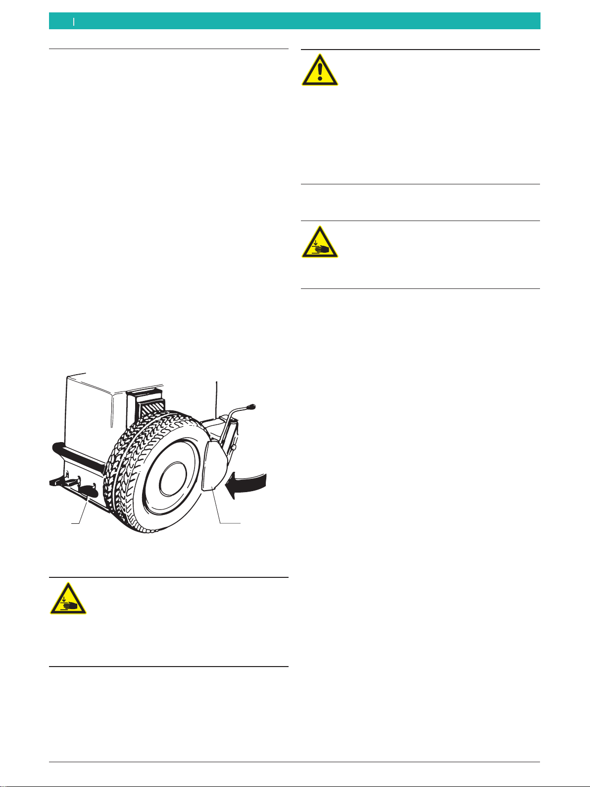
2. Before starting bead breaking operations adjust the
3 position device according to tire width.
3. Place the wheel on the floor, close to the antiabra-
sive supports of the bead breaker; to put the blade
(1) close to the bead press the bead breaker control
pedal (2). The operation has to be carried out in dif-
ferent points of the wheel (rotating it manually) until
the bead doesn't come off completely.
iLubricate the side of the tire and the rim shoulder
with mounting paste to make the bead breaking
operations easier.
652012-15_Mi
1
2
4. Repeat the operation on the opposite side of the
wheel.
Warning – limb injury danger!
During operation of the bead breaking arm,
be careful in order to avoid that the limbs are
not crushed between the tire and the bead
breaker.
¶Do not insert limbs between the tire and
the bead breaking arm.
Warning – damage risk for RFT or UHP tires!
Cracks in case of operation on cold tire. Tire
explosion in case of high speed.
¶Inner temperature of the tire must be at
least 15 °C.
¶Read the Wdk publications available in Ger-
man and English! (www.wdk.de: mounting/
demounting instructions – tire overheating)
¶Before mounting put the tire in a temperate
room.
5.2.2 Demounting
Warning – hand injury danger!
During locking plate rotation there is a risk of
crush injuries.
¶Do not insert the fingers between the tire
and the rim.
iIn case of remarkable width rims, lift the 2 position
column by means of the dedicated switch.
1. Turn counter-clockwise the locking knob to unlock
the sliding rod.
2. Press the tilting column pedal to tilt the column
backwards.
3. For external locking of the rim press the locking jaws
pedal to prepare the jaws in the open position;
iIn case of internal locking the jaws have to be in the
closed position.
4. Place the wheel on the locking plate
5. Exerting with the hand a pressure on the rim, press
(and release immediately) the locking jaws pedal in
order to lock it.
6. Lubricate with mounting paste the side of the tire till
the edge of the rim.
7. Press (and release immediately) the tilting column
pedal to lower the column.
8. Bring the mounting tool close to the rim until the
roller touches the edge of the rim; by turning clock-
wise the locking knob you achieve automatic hori-
zontal and vertical spacing from the rim and the arm
locking.
9. Insert the bead breaking lever between the mounting
tool and the bead of the rim. To make this operation
easier bring the bead in the part opposite to the
mounting tool inside the semi drop centre of the rim.
iIn case RFT or UPH tires the use of accessories like
clamps, wedge or of the TECNOROLLER SL bead
breaker is suggested.

1 697 630 500 2013-03-05
|
Beissbarth GmbH
Operating instructions | MS 65 OR RAC S80 | 15 en
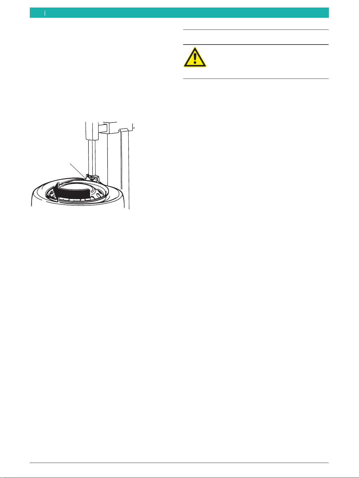
10. With the provided bead breaking lever lift the
edge of the tire and put lay it on the mounting tool
tab (1).
11. Press the rotation pedal to rotate clockwise
the locking plate, until complete ejection of the bead
from the rim.
652012-16_Mi
1
iIn case of tires with tube, press the tilting column
pedal to tilt the column and extract the tube.
12. Repeat the same operations to make the se-
cond bead come out.
13. Press the tilting column pedal to tilt the co-
lumn and remove the tire.
5.3 Tire mounting
Danger of car accidents caused by damaged
rims or tires!
In case of tire or rim damage during moun-
ting dangerous or even lethal situations may
occur during driving.
¶The operator has to be specifically trained.
¶Do not exert excessive forces on the tire or
the rim, adjust the slow rotation speed.
¶Use a sufficient quantity of mounting
paste.
¶In case of anomalies, e.g. suspicious noi-
ses, stop mounting immediately.
¶For mounting of critical rim/tire combina-
tions, read the Wdk publications available
in German and English!(www.wdk.de:
mounting/demounting instructions – crite-
ria catalogue).
5.3.1 Mounting preparations
Warning – damage risk for RFT or UHP tires!
Cracks in case of operation on cold tire. Tire
explosion in case of high speed.
¶Inner temperature of the tire must be at
least 15 °C.
¶Read the Wdk publications available in Ger-
man and English! (www.wdk.de: mounting/
demounting instructions – tire overheating)
¶Before mounting put the tire in a temperate
room.
14. Lubricate with mounting paste the inside of the
rim in correspondence of the edge and of the shoul-
der of the rim and of the semi drop centre.
15. Lubricate the two tire beads with mounting
paste.
16. Lean the tire oblique on the rim.
5.3.2 Mounting
Warning – hand injury danger!
During locking plate rotation there is a risk of
crush injuries.
¶Do not insert the fingers between the tire
and the rim.
iIn case of remarkable width rims, lift the 2 position
column by means of the dedicated switch.
1 697 630 500 2013-03-05
| Beissbarth GmbH
16 | MS 65 OR RAC S80 | Operating instructionsen
1. Rotate the locking plate and bring the valve between
2 o'clock and 4 o'clock position.
2. Press (and release quickly) the the tilting column
pedal to lower the column.
3. Lay the tire bead on the lower left edge of the moun-
ting tool tab.
4. While holding the bead in the semi-drop centre press
the rotation pedal and keep turning the locking plate
until the upper tire bead has passed close to the
mounting tool (1) and it has gone under the edge of
the rim.
652012-17_Mi
1
iBe sure that the bead is inserted in the drop centre
of the rim in order to eliminate bead yields; in order
to make his operation easier, it is suggested, during
rotation of the locking plate, to assist with a bit of
pressure the insertion of the bead in the rim.
iIn case of tires with tube, press the tilting column
pedal to tilt the column backwards; place the rim so
that the valve hole of the tube is positioned at about
90° degrees relatively to the mounting tool position
and, if needed, the tube.
5. Repeat the same operations for the insertion of the
second bead.
iIn case of RFT or UPH tires, in order to hold the bead
inside the semi drop centre, the use of accessories
like clamps, wedges or of the TECNOROLLER SL
bead breaker is suggested.
6. Press the tilting column pedal to tilt the column
backwards.
7. Press the locking jaw pedal to release the rim.
5.4 Inflation
Inflation can generate potential danger
situations. The operator has to carry out the
necessary precautions in order to guarantee
operational safety.
!Safety device:
To protect the operator from eventual dangers that
can occur during tire inflating on the locking plate,
the MS 65 OR RAC S80 has been equipped with a
valve that limits operational pressure to 3,5 bar.
5.4.1 Inflation with inflation gun
1. Screw the valve element.
2. Connect the inflation gun to the tire valve.
3. Inflate the tire, by operating on the inflation gun until
reaching nominal pressure.

1 697 630 500 2013-03-05
|
Beissbarth GmbH
Operating instructions | MS 65 OR RAC S80 | 17 en
5.5 Functioning anomalies
In the following table all the possible anomalies and their correspondent remedies are listed.
Other supposable functioning anomalies are mainly of technical nature and have to be verified and resolved by
qualified technicians.
In any case contact the assistance service of the authorized vendor of Bosch equipment.
iTo speed up intervention it is important to tell during the phone call the data reported on the identification
plate (tag on the back of the MS 65 OR RAC S80) and the type of malfunction.
!Any intervention on the electrical, hydraulic or pneumatic system, has to be performed exclusively by qualified
technicians which are properly trained.
Anomalies Causes Remedies
The locking plate does not turn in any of the two directions. 1. The network plug is not con-
nected.
2. The network plug is not cor-
rectlyconnected.
3. The tension does not corres-
pond tothe prescribed value.
1. - 2. Check if the network plug
is correctly inserted in the socket
and check connection.
3. Check the tension oftension.
When the locking flange pedal is pressed down, the locking
plate turns clockwise.
1. Phases inversion duringplug
connection.
2. The pedal is pulled up with the
foot.
1. Invert the 2 phases in the net-
work plug (qualifiedelectrician is
required).
2. Press down the pedal.
The locking plate transmits insufficienttorque (low force). 1. Wrong network tension.
2. Wrong phases connection in
the plug.
3. Loosen transmissionbelt.
1. Check the correspondence of
the network tension and the ten-
sion shown on theidentification
plate.
2. Check that the phases in the
plug are correctly connected.
3. Pull the transmission belt.
The locking plate does not lock the rim correctly. 1. The pneumatic sys-
tem is not connected to the
MS 65 OR RAC S80.
2. Insufficient pressure inthe
pneumatic system.
3. The pressure reducing valve is
closed or incorrectly adjusted.
1. Connect the pneumaticsystem.
2. Adjust pneumatic pressure to
the correct value.
3. Open or adjust correctlythe
pressure reducingvalve.
The bead breaker force is not enough for bead breaking. 1. Excessive pressure isexerted.
2. The pneumatic sys-
tem is not connected to the
MS 65 OR RAC S80.
3. Insufficient pressure inthe
pneumatic system.
4. The pressure reducing valve is
closed or wrongly adjusted (valid
for the versions that use this kind
of device).
5. The tire is not completely de-
flated.
1. Exert the right pressure on the
bead breaker.
2. Connect the pneumaticsystem.
3. Adjust pneumatic pressure to
the correct value.
4. Open or adjust correctlythe
pressure reducingvalve.
5. Remove the valve element from
the valve until complete deflation
of the tire.
1 697 630 500 2013-03-05
| Beissbarth GmbH
18 | MS 65 OR RAC S80 | Maintenanceen
6. Maintenance
6.1 Suggested lube
Component Lube Standard
Gearbox ESSO Spartan EP460 ISO 460
DIN 51502-CLP
ISO 34-98-CC
Pneumatic system
(conditioning assem-
bly)
ESSO FEBIS K 32 ISO VG 32
Tab. 1: Lubricants table.
!The manufacturer is not liable for any damage
caused by use of lubes different from those shown in
the table.
6.2 Cleaning and servicing
Before any cleaning or maintenance interven-
tion, disconnect the MS 65 OR RAC S80 by
means of the main switch and disconnect the
network plug.
Before any cleaning or maintenance interven-
tion, disconnect the pneumatic system of the
MS 65 OR RAC S80.
To guarantee full efficiency of the MS 65 OR RAC S80
and to ensure functioning without anomalies it is essen-
tial to clean the machine regularly and carry out perio-
dical maintenance.
Maintenance has to be carried out by the operator
in accordance with the manufacturer's prescriptions
shown here below.
6.2.1 Maintenance intervals
Maintenance
weekly
monthly
annual
Clean the mechanical moving parts, spray
them with nebulized oil or cherosene and lube
with appropriate grease
x
Remove the condensate from the filter assem-
bly. x
Check oil level in the oil nebulizer. x
Check transmission belt tensioning in order to
avoid its sliding. x
Check the oil level in the gearbox and keep it
always between minimum and maximum level. x
Change oil in the oil nebulizer. x
6.2.2 Condensate removal
1. Turn left the red button placed in the lower part of
the water separator.
2. Remove the accumulated condense by pressing the
same button.
3. Turn back in previous position the red button placed
in the lower part of the water separator.
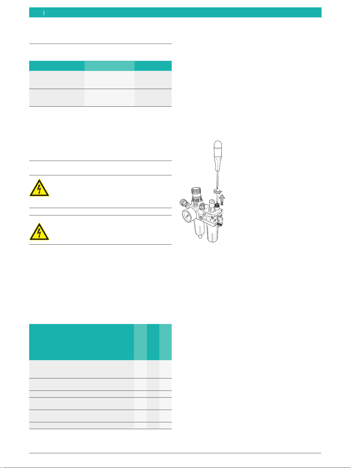
6.2.3 Nebulizer oil refill
1. Disconnect pneumatic connection.
2. Unscrew the tank cap on the oil nebulizer.
3. Top up oil (see lube table).
652002-15_Mi
6.2.4 Change oil in the oil nebulizer
1. Disconnect pneumatic connection.
2. Unscrew the tank cap on the oil nebulizer.
3. Discharge oil and dispose it (see chap. 7.3).
4. Top up with new oil (see lube table).

1 697 630 500 2013-03-05
|
Beissbarth GmbH
Decommissioning | MS 65 OR RAC S80 | 19 en
7. Decommissioning
7.1 Place change
Procedure:
1. Disconnect electrical connection.
2. Disconnect pneumatic connection.
3. Dismantle the column switch and lean it at the side.
4. Follow what shown for first start up (see chap. 4.2).
5. Fix again the MS 65 OR RAC S80 with its 3 screws
on the pallet (see chap. 4.2).
iIn case of sale or transfer of MS 65 OR RAC S80, all
the documents included in the consignment volume
has to be integrally handed over together with the
equipment.
7.2 Temporary decommissioning
If the MS 65 OR RAC S80 is going to be stopped for a
limited period of time or if the equipment is not being
used for other reasons, always disconnect the network
plug from its socket!
It is suggested to clean accurately the
MS 65 OR RAC S80, also its tools and accessories, and
carry out a protection treatment (e.g. spraying of a thin
oil film).
7.3 Disposal
¶Disconnect the MS 65 OR RAC S80 from the mains
tension and take off the power supply cable.
¶Oil are water pollution risk fluids and have to be
disposed of in accordance with the rules in force.
¶Disassemble the MS 65 OR RAC S80, order the
materials according to the category it belongs to and
dispose of them according to the rules in force.
MS 65 OR RAC S80 complies to the rules of
the European directive 2002/96/CE (directi-
ve on the disposal of electrical and electro-
nic waste).
Electric and electronic devices which are out
of order, together with their cables, accesso-
ries, accumulators and batteries, have to be
disposed of separately from household waste.
¶For disposal of such products, use the
available return and collection systems.
¶The correct disposal of the
MS 65 OR RAC S80 makes it possible to
avoid environmental damage and to put at
no risk the life of people.
8. Technical data
8.1 MS 65 OR RAC S80
Function Specifications
Maximum noise level 75 dB
Bead breaking cylinder force 25000N(2,5t)
Compressed air supply 8 – 12 bar
Power supply tension depending on the cho-
sen tension (see iden-
tification plate)
8.2 Dimensions and weights
Function Specifications
MS 65 OR RAC S80 (H x W x D) 1830 x 1860 x 1110 mm
Net weight 217kg
Gross weight 245kg
8.3 Reach
8.3.1 Car wheels
Function min / max
Tire width 3"– 12"
Maximum tire diameter 1000 mm
Rim diameter (internal locking) 12"– 28"
Rim diameter (external locking) 10"– 26"
8.3.2 Motorcycle wheels
Function min / max
Tire width 3"– 10"
Maximum tire diameter 1000 mm
Rim diameter 15"– 28"
iTo operate on motorbike wheels it is necessary to
install the motorbike wheel connection device, avai-
lable upon request (see chap. 3.4).

1 697 630 500 2013-03-05
| Beissbarth GmbH
20 | MS 65 OR RAC S80 | Glossaryen
9. Glossary
Rim, structure and names
652001-26_Rf
1
1
3
4
3
2
D
Fig. 4: Rim
1 Rim edge
2 Rim shoulder
3 Hump (lifted edge)
4 Semi drop centre
D Rim diameter
RFT
Run Flat Tyre, tire with emergency functioning features,
normal wheel and spare wheel at the same time.
TCE
Tyre Change Equipment, abbreviation for tire changer.
UHP
UltraHighPerformance tires, name of the brand of a tire
for high speeds.
wdk
German rubber industry association
(registered association).
Table of contents
Other Beissbarth Tyre Changer manuals


