Beissbarth Start Line MS 201 User manual

Start Line MS 201
de
Originalbetriebsanleitung
Reifenmontiermaschine
en
Original instructions
Tire changer
fr
Notice originale
Machine à monter les pneus
es
Manual original
Máquina para montaje de neumáticos
it
Istruzioni originali
Smontagomme
pt
Manual original
Máquina de montagem de pneus
Reifenmontiergeräte
Tyre Changers

| Start Line MS 201 | 27 en
1 695 108 073 2016-07-27|Bosch Automotive Service Solutions srl
Content English
1. Symbols used 28
1.1 In the documentation 28
1.1.1 Warning notices -
Structure and meaning 28
1.1.2 Symbols in this documentation 28
1.2 On the product 28
1.3 Warning 28
2. User instructions 29
2.1 General provision 29
2.2 Range of application 29
2.3 Safety requirements and notes 30
3. Product description 31
3.1 Intended use 31
3.2 Machine rating plate 31
3.3 Device description 31
4. Transport 32
4.1 Transport and packing 32
4.2 Transport method 32
5. Unpacking 32
5.1 Unpacking 32
5.2 Setting up the MS 201 32
3.4 Scope of delivery 32
6. Initial commissioning 34
6.1 Initial commissioning 34
6.2 Fastening the MS 201 35
6.3 Connecting the MS 201 to power and the
compressed air supply 35
6.4 Checking the pedal functions 35
7. Operation 36
7.1 Safety notice 36
7.2 Check before use 36
7.3 Information about special rims and tires 36
7.4 Unseating the tire bead 37
7.5 Rim location direction 38
7.6 Clamping the rim 39
7.6.1 Clapping the rim from the outside: 39
7.6.2 Clamping the rim from the inside: 39
7.7 Demounting the tire 39
7.7.1 Positioning of the mounting head 40
7.7.2 Lever the top bead over the rim flange 40
7.7.3 Demounting the top bead 41
7.7.4 Demounting the bottom bead (with the
aid of the mounting head) 41
7.7.5 Removing wheels 41
7.8 Mounting the tire 41
7.8.1 Selecting the tire 42
7.8.2 Preparing the tire 42
7.8.3 Positioning of the mounting head 42
7.8.4 Mounting the lower tire bead 42
7.8.5 Mounting the top bead 42
7.9 Procedure for mounting/demounting alloy rims43
8. Inflation 43
8.1 Inflating tubeless tires 44
8.2 Inflating tubed tires 44
9. Maintenance 45
9.1 Warning 45
9.2 Maintenance operations 45
9.2.1 Maintenance unit and bead breaking
cylinder 45
9.2.2 Belt 46
10. Troubleshooting 47
11. Decommissioning 48
11.1 Change of location 48
11.2 Temporary shutdown 48
11.3 Disposal and scrapping 48
11.3.1 Substances hazardous to water 48
11.3.2 MS 201 and accessories 48
12. Technical Parameter 49
12.1 Dimensions for 49
12.2 Range of application 49
12.3 Turntable type 49
12.4 Bead breaker blade 49
12.5 Power 49
12.6 Pneumatic diagram 49

1 695 108 073 2016-07-27| Bosch Automotive Service Solutions srl
28 | Start Line MS 201 | Symbols useden
Danger – Attention electricity !
Risk of injuries, heart failure or death from
electric shock when touching live parts (e.
g. main switch, circuit boards).
¶Work on electrical installations or
equipment is only to be performed by
qualified electricians.
¶Cut the power supply to the MS 201
before opening it.
Direction of wheel rotation
Wheel must turn in direction indicated.
1.3 Warning
Wear safety goggles.
Study the original operating instructions
prior to operation.
Risk of injury from rotating and moving
parts.
1. Symbols used
1.1 In the documentation
1.1.1 Warning notices -
Structure and meaning
Warning notices warn of dangers to the user or
people in the vicinity. Warning notices also indicate
the consequences of the hazard as well as preventive
action. Warning notices have the following structure:
Warning
symbol
KEY WORD – Nature and source of hazard!
Consequences of hazard in the event of
failure to observe action and information
given.
¶Hazard prevention action and information.
The key word indicates the likelihood of occurrence and
the severity of the hazard in the event of non-observance:
Key word Probability of
occurrence
Severity of danger if
instructions not observed
DANGER Immediate impending
danger
Death or severe injury
WARNING Possible impending
danger
Death or severe injury
CAUTION Possible dangerous
situation
Minor injury
1.1.2 Symbols in this documentation
Symbol Designation Explanation
!Attention Warns about possible property damage.
iInformation Practical hints and other
useful information.
1.
2.
Multi-step
operation
Instruction consisting of several steps.
eOne-step
operation
Instruction consisting of one step.
Intermediate
result
An instruction produces a visible
intermediate result.
"Final result There is a visible final result on
completion of the instruction.
1.2 On the product
!Observe all warning notices on products and ensure
they remain legible.

User instructions | Start Line MS 201 | 29 en
1 695 108 073 2016-07-27|Bosch Automotive Service Solutions srl
2. User instructions
2.1 General provision
¶This operating manual is an essential part of the
product. Before operating the device, please read
and heed the warnings and instructions in the
operating manual. It contains important information
on safe operation and maintenance.
¶Leave the operating instructions and warnings in
the operating manual and on the MS 201. Please
keep this operating manual in a safe location for use
at a later date and in its entirety in the event the
device is sold.
¶If the operator reads the operating manual carefully,
the operator can operate the MS 201 correctly and
safely.
¶Please read the operating manual carefully before
connecting the voltage supply and compressed air
supply.
¶Please carefully retain all information and data
supplied and provided.
¶Different tire changers come with different
operating manuals. The operator must check that
the operating manual is the correct one for the
device.
!The MS 201 must be used for the purpose stated
in the operating manual. The manufacturer and its
authorized dealers assume no responsibility for
problems caused by incorrect operation.
!The MS 201 must be operated by technically
capable personnel. The operator must fully
understand the operating manual and have received
professional training. If untrained personnel operate
the MS 201, personal injury and damage to the
tire and rim may result.
!The MS 201 has been designed for use by
personnel with basic mechanical and electrical
skills. For this reason, the description of basic
operations such as how to tighten screws may
not appear in the operating manual. Never allow
inexperienced personnel to operate the MS 201.
If you have any questions in this regard, please
contact your authorized dealer for assistance.
iAll of the figures in the operating manual show
the MS 201 in its original design. The structure
shown may be different from the actual structure of
the machine.
2.2 Range of application
The MS 201 is an electropneumatic tire changer
for passenger cars. Information about the work area
(weight/size) can be found in the Technical Data
section.
Applicable tire types:
RTire standard tire
RReverse tire
RTire without center hole
RRun flat tire (with assist arm)
!Each type of tire has its own specific method of
operation.
!Notice: When demounting / mounting the tire of an
old car (more than 30 years old) / modified car tires
/ tires with a modified rim, accidents may happen.

1 695 108 073 2016-07-27| Bosch Automotive Service Solutions srl
30 | Start Line MS 201 | Symbols useden
2.3 Safety requirements and notes
¶The MS 201 must only be operated by authorized
personnel who have received special training.
¶The manufacturer assumes no liability for any
direct or indirect damage arising from modification
of the MS 201 without the permission of the
manufacturer.
¶The MS 201 machine comes from the factory
with a complete set of instructions and warning
signs. If for some reason these have been damaged
or destroyed, they must be replaced.
¶The MS 201 must be kept away from flammable
and explosive materials.
¶The MS 201 must also be kept out of direct
sunlight and glare.
¶The installation site must be well ventilated.
¶Be sure to use original parts and accessories.
¶The MS 201 must be installed by authorized
personnel in the manner described in the operating
manual.
¶During operation, you should pay attention whether
there is any danger. If a hazard is detected, shut
off the MS 201 immediately and notify the
authorized dealer.
¶When the tire changer running, unauthorized
personnel should be kept away from the machine.
¶The operator must wear protective gear such as
protective gloves, safety goggles and overalls to
prevent accidental injury.
¶The protective conductor must be connected
correctly.
¶When the tire changer is being operated,
unauthorized personnel should be kept away from
the machine.
¶Failure to observe the requirements for operation
or to heed the warnings related to the dangers
specified in the operating manual poses the risk of
injuries to the operators or personnel nearby.
¶The MS 201 must be operated by technically
capable personnel. The operator must have received
special training and understood the requirements in
the operating manual.
¶He or she must also understand related safety
requirements and the requirements for operation.
¶The operator must not operate the MS 201 after
consuming alcoholic beverages.
¶The operator must pay attention to the following:
$All requirements in the operating manual must be
understood.
$The operating principle of the tire changer must
be clear.
$Unauthorized personnel should be kept away
from the MS 201 during operation.
$It is necessary to ensure that installation of the
MS 201 complies with applicable local laws
and regulations.
$It must be ensured that the operators have
received training and have the skill to operate the
MS 201, and they must be monitored.
$Do not detach bolts, nuts or the other
components from the MS 201.
$Do not touch the motor and live parts on the
machine such as connection cables before the
voltage supply has been disconnected.
$Carefully read the operating manual and learn
how to use the MS 201 correctly and safely.
$Keep the operating manual for the future
reference.
¶Do not detach the danger labels, safety warnings
and operation tips on the MS 201.
¶If there is any damage, please contact the local
authorized dealer promptly.
$During the process of use and maintenance, the
operator should pay attention to the danger of
the high electrical voltage.
$Do not modify the MS 201 or use anything
other than original parts.
$The operators must wear tight overalls, gloves,
safety goggles, and safety shoes, etc.
$When the operator makes operation or
maintenance, it is forbidden to wear loose
clothes, necklace or long hair.
Product description | Start Line MS 201 | 31 en
1 695 108 073 2016-07-27|Bosch Automotive Service Solutions srl
3. Product description
3.1 Intended use
MS 201 is used to demount/ mount the car tire. The
dimension of the rim is 9”-22”. The maximum wheel
diameter is 1050mm, the maximum tire width 13". Any
other use shall be construed as improper use.
!The manufacturer assumes no liability for any
damage arising from operation in a manner not
specified in this operating manual.
3.2 Machine rating plate
Each MS 201 is equipped with an identifying plate
that lists the technical parameters and serial number.
It is prohibited to remove the rating plate from the
MS 201.
iEach MS 201 is equipped with an identifying
plate that lists the technical parameters and serial
number.
Symbol Meaning
V Rated voltage
A Rated current (during operation)
kW Power
Hz Frequency
Ph Phase of the voltage supply
bar Operating pressure from the compressed air
supply
Serial N. Serial number of the MS 201
CE CE marking
iComplete information on the model and serial
number will help our technical personnel provide
you with service and technical support. It will also
make replacement of parts more accurate and
easier. If there is difference between the data in
the operating manual and the data on the rating
plate, that on the rating plate should be considered
correct.
3.3 Device description
!All information about the MS 201 must have
been understood. It must be clear how
$accidents can be avoided.
$the tire changer must be operated.
$the functions and control elements can be used.
!Accidents can be prevented only if every step
required for operation is understood.
!The MS 201 must be installed correctly, operated
correctly and also serviced periodically.
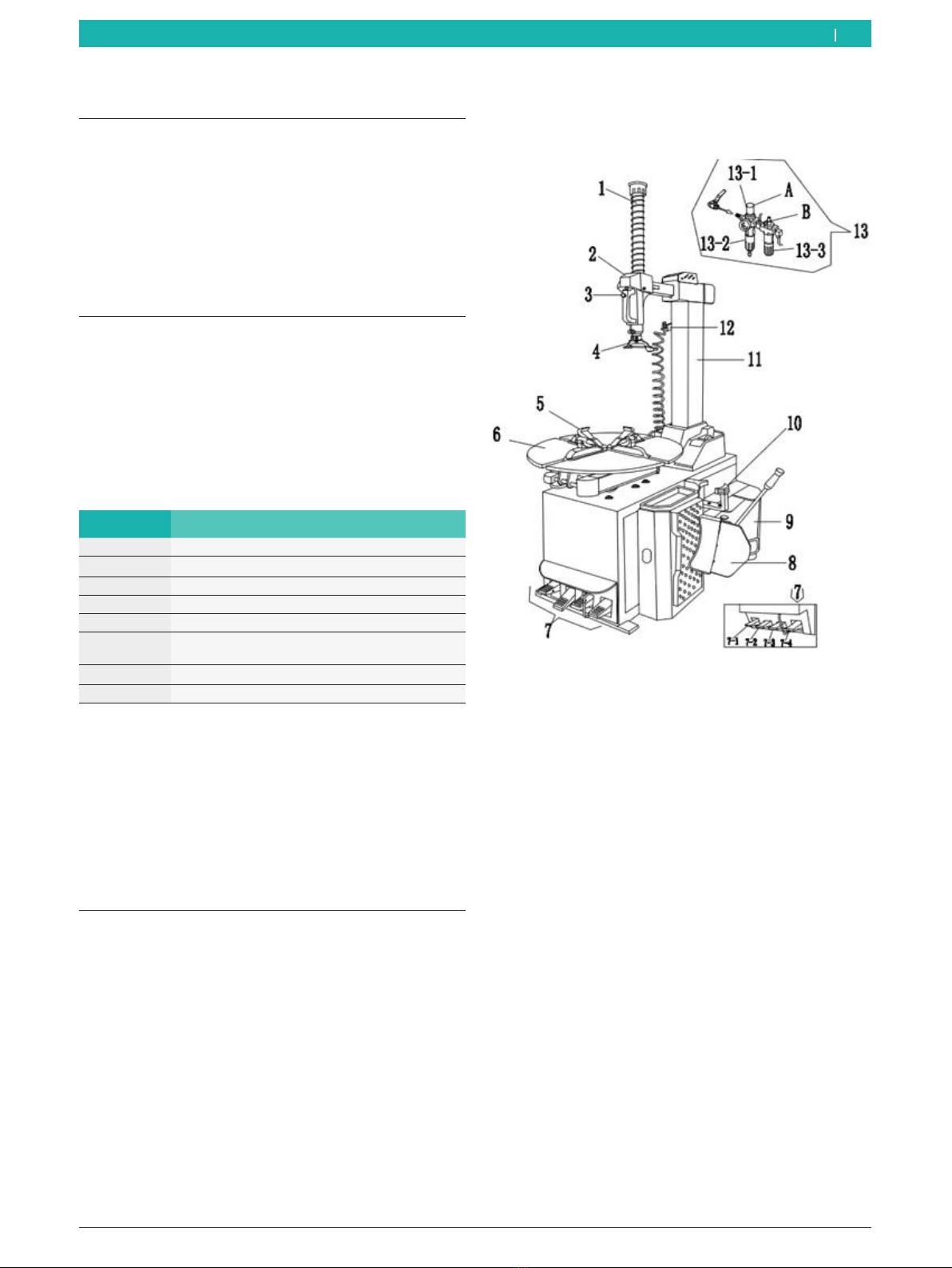
Fig. 1: Product description MS 201
1 Hexagon shaft: for securing the mounting head
2 Cover: dust prevention
3 Mounting arm locking valve: for locking/unlocking the mounting
arm
4 Mounting head: the tool for demounting/mounting the tire
5 Clamp jaw: for clamping the rim
6 Turntable: for placing the wheel
7 Pedal control system
7-1 Mounting arm control pedal: controls pivoting of the mounting
arm
7-2Clamping jaw control pedal: control open/close of the clamping
jaw
7-3Blade control pedal: control the blade movement
7-4Turntable rotation control pedal: control the rotation of the
turntable
8 Bead-breaker blade: for unseating the tire from the rim
9-Blade arm: supports the bead breaker blade
10 Lubricant holder: conveniently positioned for fastening a variety
of lubricant containers
11-Column: support horizontal arm
12-PCL Inflation gun: inflating for the tire
13-Air treatment assembly
13-1 Pressure-limiting valve, for regulating the supply pressure
13-2 Water separator
13-3 Atomized lubricator: provides oil for the air passages
1 695 108 073 2016-07-27| Bosch Automotive Service Solutions srl
32 | Start Line MS 201 | Product descriptionen
4. Transport
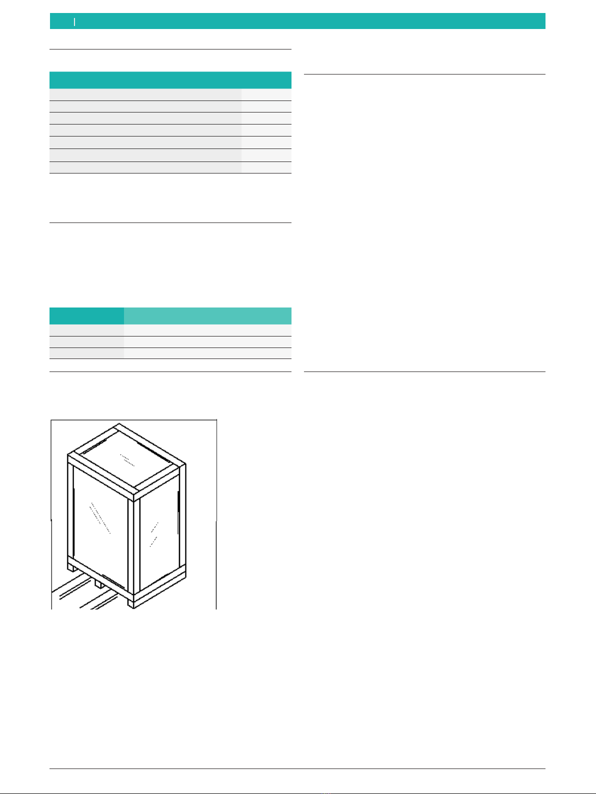
4.1 Transport and packing
The MS 201 must be placed in the original
packaging for transport. The package should comply
with the following requirements.
The package size requirement:
Dimensions Package size
Width 1150mm
Length 1200mm
Height 1050mm
4.2 Transport method
¶Open the top package, plug the fork of the forklift
from bottom of the original package.
iKeep the original package for the future
transporting.
5. Unpacking
5.1 Unpacking
¶When unpacking, the operator should wear the
proper protective gear such as protective gloves.
¶Check the delivery carefully to make sure that all
parts have been delivered. If there is any mistake,
please contact your authorized dealer at once.
¶The objects in the carton, such as boards, nails,
screws and plastic bags, should be stored in a safe
location.
¶If there are any environmentally harmful or non-
degradable substances, you should treat them in
accordance with local laws and regulations.
!During the process of unpacking, assembly and
transporting, you should follow the following
requirements and handle with care. Otherwise, the
MS 201 could be damaged.
1. Detach the upper cover of the carton and make
sure whether there is any damage or not during
transporting.
2. Find the fastening screws holding the MS 201 on
the pallet.
5.2 Setting up the MS 201
!Steps 1 - 11 must be completed on the pallet. Do
not loosen the screw and secure the mounting arm
until installation is complete while the MS 201 is
being moved.
1. Fasten the hoisting strap (mod. DR 750, 3m and DR
735, 1.5m, factor 6:1).
!Hoisting strap requirement: more than 1 metric ton
and safety factor 6:1.
2. You should use the above method whenever the
MS 201 is moved.
!Do not move the MS 201 unless the MS 201
has been disconnected from the voltage and
compressed air supplies.
3.4 Scope of delivery
Denomination Quantity
MS 201 1
Bead beaker assembly 1
Mounting lever 1
Inflation gun with pressure gauge 1
Bead breaker cover 1
Protection cover claw 1
Mounting tool cover 1
Unpacking | Start Line MS 201 | 33 en
1 695 108 073 2016-07-27|Bosch Automotive Service Solutions srl
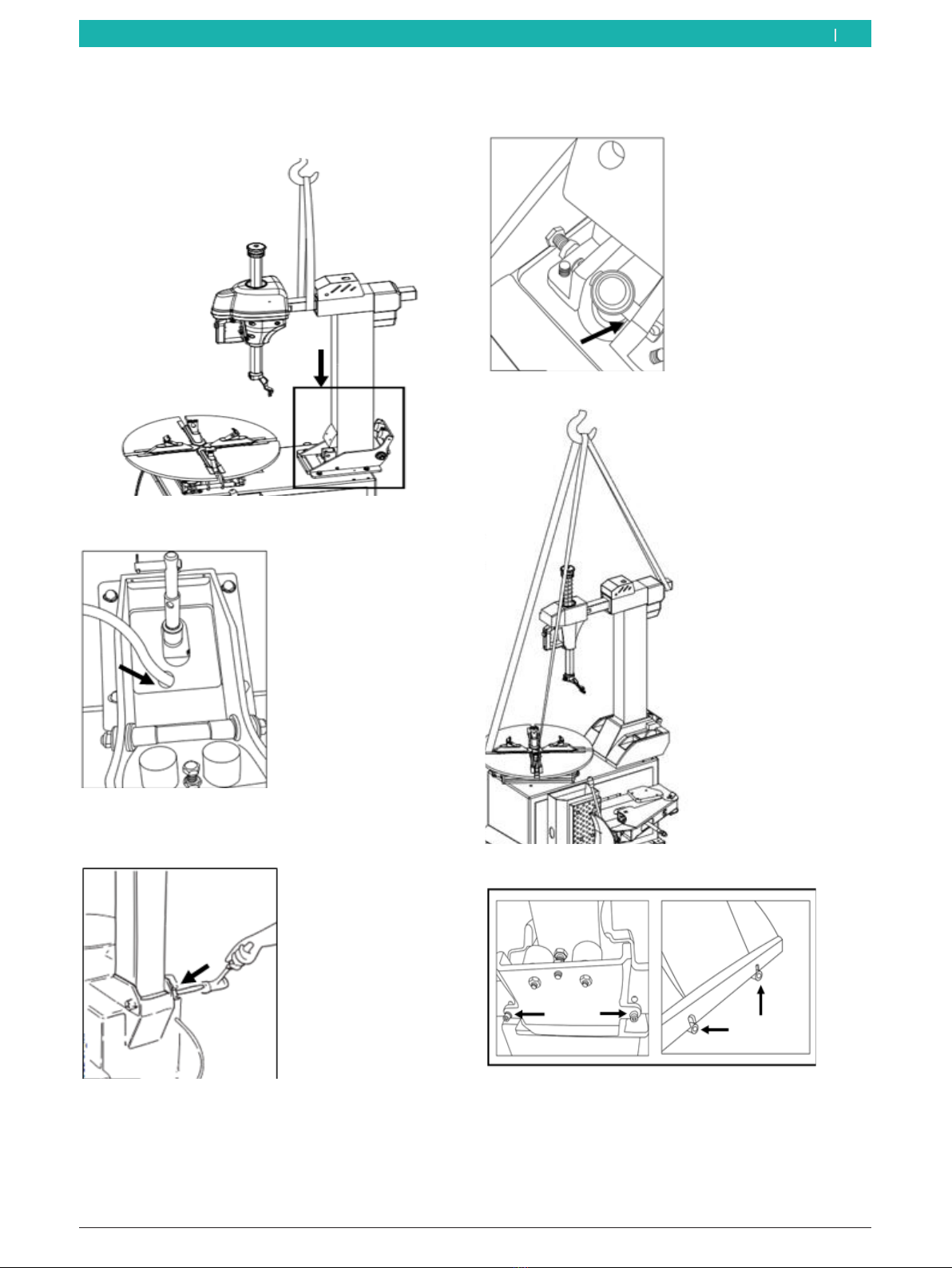
3. Lift the mounting arm onto the MS 201 as shown
in the figure below.
4. Put the air pipe that inside column into the machine
body.
5. Position the MS 201, then drive the fixed axis
insert into the corresponding holes with a hammer
and fasten.
6. Connect the fixed axis insert to the bead breaker
cylinder and mounting column, and then fasten.
7. Before lifting the complete MS 201.
8. Affix the cover then fasten the screw.
1 695 108 073 2016-07-27| Bosch Automotive Service Solutions srl
34 | Start Line MS 201 | Unpackingen
6. Initial commissioning
6.1 Initial commissioning
Installation environment requirement:
Initial commissioning Requirement
Temperature 4 - 40ºC
Sea level <1000m
Humidity
at 40°C
at 20°C
50%
90%
1. When selecting the installation location, ensure that
the MS 201 is safe when it is used under normal
operating conditions.
2. The MS 201 must be connected to the voltage
supply and compressed air suppl; we thus
recommend that the MS 201 be set up close to
these two utilities.
3. Installation position should at least leave the space
in the following figure to secure free movement of
each part of the machine.
4. If the MS 201 is installed outdoors, you should
take measures to protect it from rain and sun. The
MS 201 is not intended to be used outdoors.
5. The work are should enjoy enough light to secure
the operators can observe each details of the
operation.
!Besides the operator, no other personnel should be
in the work area when the machine is running.
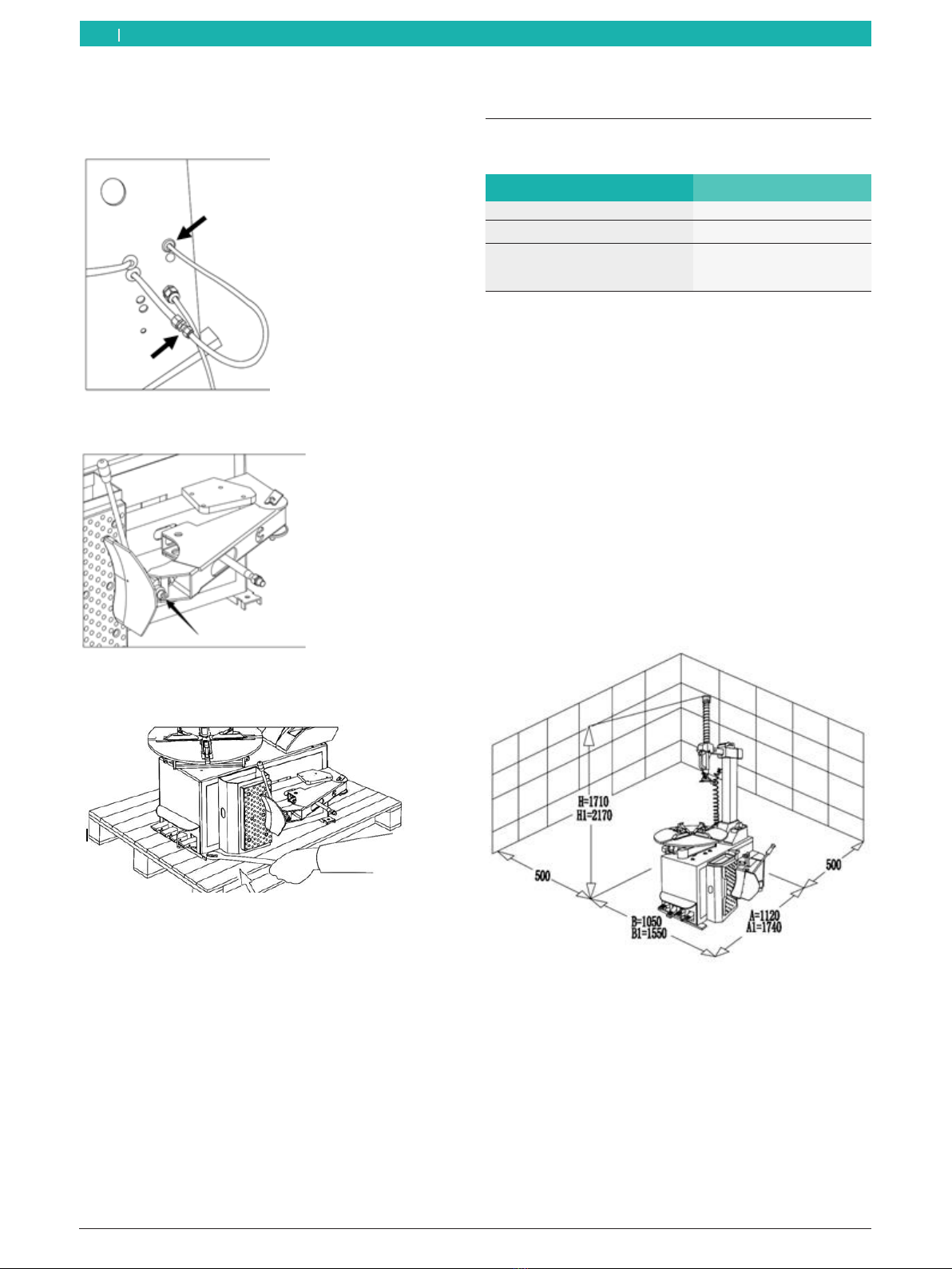
9. To connect the air hose, open the side panel of
machine housing, then attach the air hose to the
straight connector.
10.Assemble the bead-breaker blade, then fasten the
screws.
11.Loosen the anchor bolt, push the mounting arm
to the innermost position, and prepare the lifting
device.
Initial commissioning | Start Line MS 201 | 35 en
1 695 108 073 2016-07-27|Bosch Automotive Service Solutions srl
6.2 Fastening the MS 201
!For the procedure when lifting the MS 201,
please see the figure. Lift the MS 201 carefully
(the middle of the MS 201 is not identical with
the center of gravity) and protect the plastic covers
to prevent damaging them.
1. Detach the bolts and nuts fixed on the machine
chassis.
2. Bind the hoist tape (mod. DR 750 of 3m and DR
735 of 1.5m factor 6:1).
3. Lift the MS 201 carefully.
4. Remove the pallet and position the MS 201 at
the preselected location.
!Ensure that the nozzle and air hose on the
MS 201 are not damaged during the hoisting
operation. Be very careful when lifting the
MS 201.
iIf tires will be inflated on the turntable, you must
secure the MS 201 to the floor.
5. Use an M10 bolt (grade 12.9), placed through the
hole in the pallet, to secure the MS 201 to the
floor.
6.3 Connecting the MS 201 to power
and the compressed air supply
!In accordance with the electrical specification, the
voltage supply must be equipped with a fuse and a
properly grounded protective conductor connection
as well as a safety switch.
iIf the MS 201 does not have a plug, the user
should prepare a 16A plug suitable for the operating
voltage of the tire changer and as specified in the
electrical code.
1. Connect the MS 201 to the voltage supply.
RThe voltage deviation should be 0.9 - 1.1 times the
rated voltage range, and the frequency deviation
should be 0.99 - 1.01 times the rated frequency
range. You should take the necessary protective
methods.
ROnly qualified personnel should make the
connection to the voltage supply.
RIf the MS 201 is not being used, please
disconnect the power promptly to ensure that the
MS 201 is not switched on accidently.
RIf the MS 201 will not be used for a long time
and the machine is connected directly to the
electrical cabinet instead of via a plug, the electrical
cabinet should be locked. Only professional
personnel should be able to open the electrical
cabinet in order to ensure that the MS 201 is not
switched on unintentionally.
!The MS 201 must be grounded and the
protective conductor must not be attached to a
heater, plumbing pipe, telephone cable or the like.
2. The compressed air supply must comply with the
requirements for the tire changer. The details of
these requirements are specified in "Technical
parameters" section. The pressure and volumetric
flow of the compressed air supply should meet the
requirements of the MS 201. The pressure must
be between 8and 16bar.
3. Use the special air hose to connect the water
separator, air regulator and lubricator on the side of
the MS 201 (see figure).
4. Please make sure that the oil has been fully filled
reaching the standard oil level. The oil contained
in the lubricator should be SAE 20 oil, or the air
passage will not be lubricated, causing the sealing
kits to be damaged in a short time.
RThe user must mount an air supply shut-off valve and
pressure control valve in front of the MS 201.
6.4 Checking the pedal functions
¶Depress the turntable rotation control pedal 7-4; the
turntable will rotate clockwise.
¶And rise up the turntable rotation control pedal 7-4,
the turntable will rotate counterclockwise.
¶Step down the horizontal arm control pedal 7-1
to the lowest position and the horizontal arm will
swing out.
¶Go on to step down the horizontal arm control pedal
to highest position the horizontal arm will swing
back to the vertical position.
¶Depress the blade control pedal 7-3; the blade
executes its function.
¶Release the blade control pedal 7-3 and the pedal
returns to its original position.
¶Step down the clamping jaw open/close control
pedal 7-2 to the first gear and the clamping jaw will
open.
1 695 108 073 2016-07-27| Bosch Automotive Service Solutions srl
36 | Start Line MS 201 | Initial commissioningen
7. Operation
!The following information must be read, and will be
helpful to the operator to simplify the steps needed
for operation and reduce unnecessary trouble.
7.1 Safety notice
!The MS 201 is intended to be used only to
mount/demount passenger car tires (see the section
"Technical data").
!If an accident happens, shut off the MS 201
immediately.
$Disconnect mains plug.
$Turn off compressed air supply.
7.2 Check before use
1. Before operating the MS 201, always run the
bead breaking cylinder back and forward while
observing the lubricator to make sure it starts
feeding oil to the air passage. After you confirm
that the lubricator works normal, you can guarantee
each part of the air route system under perfect
lubrication.
2. Check the maintenance unit to ensure that the
pressure indicated on the pressure gauge of the
pressure-limiting valve is not less than 8bar.
3. Check whether the power supply connection is
correct.
7.3 Information about special rims and
tires
iSpecial process to be need for some special tires,
which different from the normal demount/ mount
process.
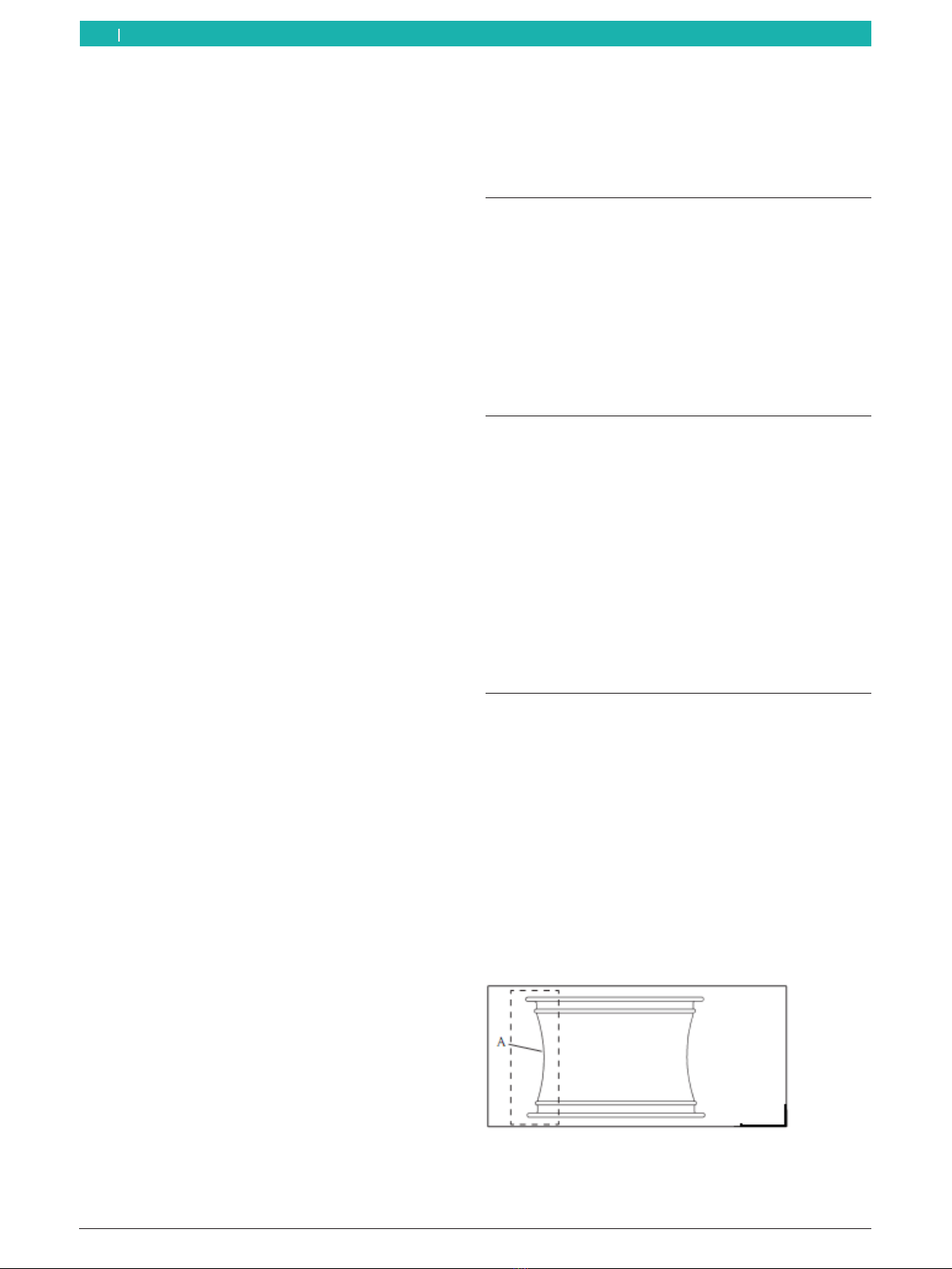
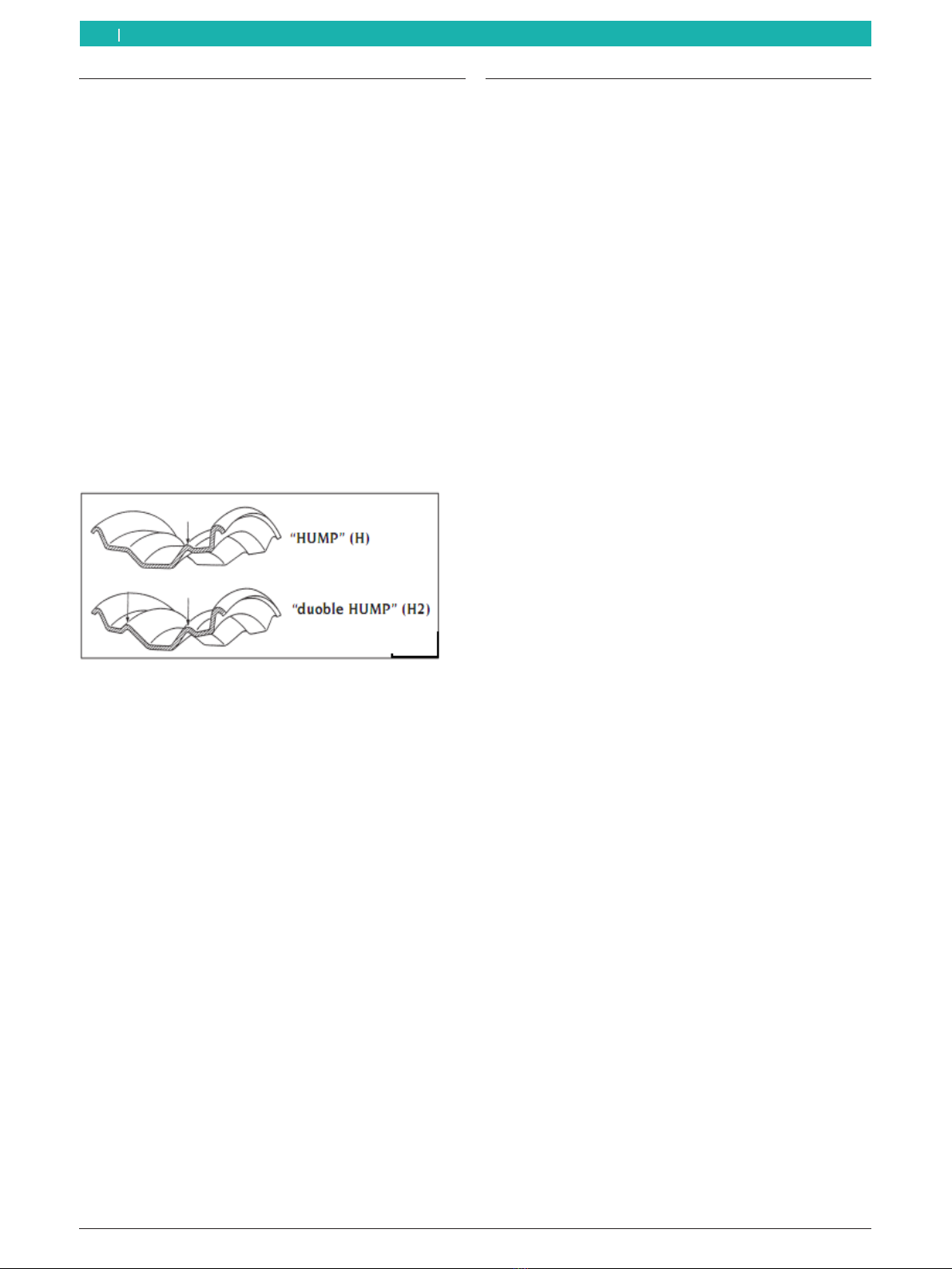
iAs shown in the figure below, some alloy rims have a
very shallow rim channel in the center of the rim. Or
the rim channel has no depression. These rims do
not meet the safety regulations for vehicular traffic
and transportation. In some countries, these types
of rim/wheel are not allowed in the market.
¶Depress the clamping jaws control pedal 7-2 to the
second position and the clamping jaws immediately
stop.
¶Depress the clamping jaws control pedal 7-2 to the
third position and the clamping jaws close.
¶When the mounting arm is at the innermost position,
it is released and tool head will drop.
¶When the mounting arm is at the middle position, it
is released and the tool head will move up.
¶When the mounting arm is at the outermost
position, the mounting arm and tool head are
locked.
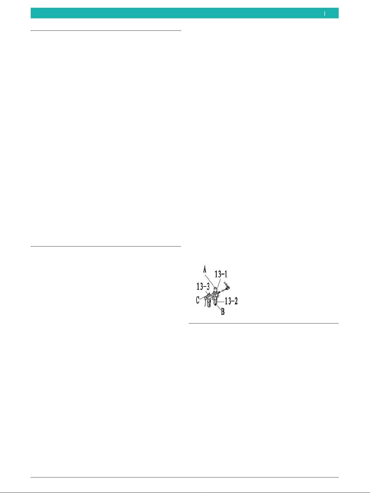
Maintenance unit
¶Pressure-limiting valve 13-1: Pull out the knob on
the top of the pressure-limiting valve A. Clockwise/
counterclockwise turning can adjust the supply
pressure to the MS 201. Press down the knob A
after adjustment.
¶Water separator 13-2: Clockwise/counter clockwise
turning knob B at the lower end of water separator
can deflate the water in the water cup.
¶Lubricator 13-3: Turning the knob at the top end of
the lubricator. Clockwise/counter clockwise turning
can adjust the oil feeding speed of the lubricator.
Note
¶The supply pressure should be in the range of
8-10bar.
¶Regularly vent the water in the water separator.
¶Move the blade cylinder back and forward,
and observe the condition of lubricator. Before
operating, ensure that oil will be fed each day.
Operation | Start Line MS 201 | 37 en
1 695 108 073 2016-07-27|Bosch Automotive Service Solutions srl
!Pay special attention when demounting/mounting
tire that the rim or tire are not damaged.
!In the process of inflating the tire, there is a risk that
the tire may burst.
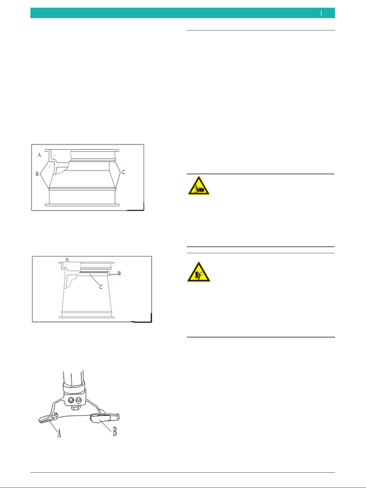
!The cross-section of some rims is that shown in the
figure below. The C position is very deep on these
rims. B is higher than A here. When you break the
bead of this type of tire, you must press the bead,
since it must be lower than the B position. When
mount the tire, the bead opposite to the mounting
head must over B point. At this moment, the bead
can be led into the groove at the middle of the rim.
!Some wheels have the tire pressure inspect system
as figure below. Do not damage the tire pressure
monitoring system when mounting/demounting
tires.
iTo protect the rim, the mounting head plastic cover
should be changed twice a month. If damaged, these
plastic parts should be changed at once.
7.4 Unseating the tire bead
!Not using the grease will seriously damage the tire.
Please use the special grease.
!Remove all balance weights on the rim.
iBefore demounting and re-mounting the tire, check
for signs of wear on all protective plastic parts.
Replace the wheel-guard hoods if necessary.
iAlways establish the rim and tire data prior to
removal/mounting. The method of attachment,
pressure and accessories required can then be
planned in advance.
1. Check whether the tire has been deflated
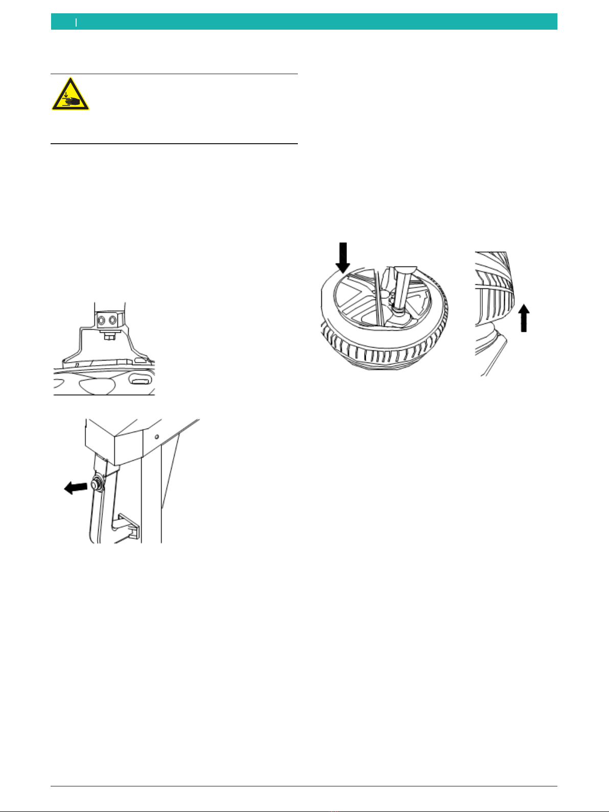
completely. If not, you should deflate at first.
Warning – Risk of injury from trapping
hands between rim-chuck plate and tire.
As the tire moves, make sure that your hands
do not get caught between the tire and rim-
chuck plate.
¶Before starting, turn the rim-chuck plate to
a position where the rim-chuck claws are
at an angle of 45° to the machine housing.
WARNING – Risk of injury to extremities!
¶Use extreme caution when operating the
bead breaker arm in order to prevent limbs
from being crushed between the tire and
the bead breaker unit.
¶Never reach between the tire and the bead
breaker arm.
¶The clamping jaws on the turntable should
be closed completely.
¶Do not open the clamping jaws while
unseating the tire bead.
2. Lean the tire against the rubber wheel support.
3. The surface of the blade will stay about 1cm away
from the rim, and the blade should rest on the tire
properly.
!Pay attention to the position of the blade to prevent
it from touching the rim after bead breaking.

1 695 108 073 2016-07-27| Bosch Automotive Service Solutions srl
38 | Start Line MS 201 | Operationen
4. Depress the blade control pedal 7-3 to make the
blade start working.
5. When the bead is broken, release the pedal at once.
6. Rotate the tire until the edge of the tire is detached
from the rim and repeat at the other side.
7. Apply lubricant to the tire.
!Not using the grease will seriously damage the tire.
Please use the special grease.
7.5 Rim location direction
How to decide from which side of the wheel to
demount tire?
1. When fix the wheel, the side of standard rim will
upward as figure.
2. Measure three dimension of A, B and C.
3. When fix the rim, the smallest size of C must be
positioned at the top position.

Operation | Start Line MS 201 | 39 en
1 695 108 073 2016-07-27|Bosch Automotive Service Solutions srl
7.6 Clamping the rim
!When the mounting arm swings out, no one is
allowed in the range of its movement.
¶Depress pedal 7-1, swing out the mounting arm and
clean the turntable.
!When clamping the tire, it is absolutely forbidden
to put your hand under the tire. To clamp the tire
correctly, you should position the tire at the very
center of the turntable.
!One operator is enough to position the tire on the
turntable if the weight is less than 25kg.
If the weight is 25kg-50kg, 2 persons will be
needed.
You will need to use the tire lifting device if the
weight exceeds 50kg.
7.6.1 Clapping the rim from the outside:
1. Depress the clamping jaws control pedal 7-2 to open
the clamping jaws.
2. Place the tire on the clamping jaws, while pressing
down the rim.
3. Place the tire on the turntable, and depress the
clamping jaws control pedal 7-2 until the rim is
clamped.
!Make sure the rim is clamped securely.
7.6.2 Clamping the rim from the inside:
1. Close the clamping jaws on the turntable.
2. Place the tire on the turntable, and the press the
pedal until the rim is clamped.
!Make sure the rim is clamped securely.
7.7 Demounting the tire
Warning: Risk of damage to the tire and rim!
Excessive contact pressure may cause
internal or external tearing in the tire. The rim
may become scratched or dented.
¶Follow the mounting and demounting
instructions of Wdk (obtainable in German
and English):
$Criteria catalog.
$Tire overheating.
¶Adjust the pressure to the type of tire.
¶Use the rim guard for easily damaged rims
(e.g. alloy rims).
Additional information on mounting runflat and UHP
tires.
Warning: Risk of damage to runflat and UHP
tires!
Danger of tire rupture (on the inside/outside)
from working at high speed and when the tire
is cold.
¶Tire core temperature at least 15°C.
¶Before demounting the tire, heat it with an
electric tire heater.
1 695 108 073 2016-07-27| Bosch Automotive Service Solutions srl
40 | Start Line MS 201 | Operationen
7.7.1 Positioning of the mounting head
Warning – Risk of hand injuries!
There is a risk of crushing hands when
rotating the rim-chuck plate.
¶Do not reach between the tire and the rim
with your fingers.
1. Press the top bead by hand to leave the space for
positioning the mounting head.
2. Depress the mounting arm control pedal to move the
mounting arm to the work position.
3. Push the button on the mounting arm lock plate to
release the hexagonal shaft.
4. Move the mounting head to the work position. The
plastic part at the nose of the mounting head should
be in contact with the rim.
5. Push the button on the mounting arm lock plate lock
the hexagonal shaft.
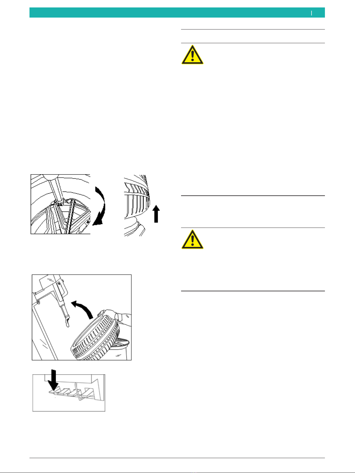
7.7.2 Lever the top bead over the rim flange
1. Hold the bead-lifting lever firmly while keeping
space for the mounting head.
iIf the space is not adequate, please refer to the
"Operation tips" section. The tips in the "Operation
tips" section will ensure successful bead breaking.
2. Check that the mounting head has grasped the tire
bead fully.
iIf there is inner tube, please turn the valve 10cm
away to the right and then proceed. This will prevent
damaging the inside of the tire.
Operation | Start Line MS 201 | 41 en
1 695 108 073 2016-07-27|Bosch Automotive Service Solutions srl
7.7.3 Demounting the top bead
1. Depress the pedal 7-4 and rotate the wheel until the
top bead is completely detached from the rim.
2. At the same time, lifting the bottom bead can help
demount the top bead.
3. If the bead slips back into the rim channel during
this process, you can take the measures described
in the "Operation tips" section to demount the top
bead.
7.7.4 Demounting the bottom bead (with the aid of
the mounting head)
1. If the tire has an inner tube, remove it.
2. Use the same process for the lower tire bead until
the tire is demounted successfully.
3. Lever the tire over the upper rim flange with the aid
of the bead-lifting lever.
4. Depress the pedal 7-4, and rotate the wheel until it
is fully detached from the rim.
7.7.5 Removing wheels
1. Swing the mounting arm to the back.
2. Remove the tire.
7.8 Mounting the tire
Risk of accident from damaged rims and
tires!
If the tire or rim is damaged during mounting,
this may lead to dangerous or life-threatening
situations when driving.
¶The tire must bemounted by trained
persons only.
¶Follow the mounting and demounting
instructions of Wdk (obtainable in German
and English):
$Criteria catalog.
$Tire overheating.
¶Do not subject tires and rims toexcessive
force.
¶Set a low speed of rotation when mounting
tires on critical wheels.
¶Use a sufficient amount of lubricant.
¶Stop the fitting process immediately in the
event of any anomalies, such as abnormal
noise.
Additional information on mounting runflat and UHP
tires.
Warning: Risk of damage to runflat and UHP
tires!
Danger of tire rupture (on the inside/outside)
from working at high speed and when the tire
is cold.
¶Tire core temperature at least 15°C.
¶Before demounting the tire, heat it with an
electric tire heater.
iRemove all of the balance weights from the wheel
rim.

1 695 108 073 2016-07-27| Bosch Automotive Service Solutions srl
42 | Start Line MS 201 | Operationen
7.8.1 Selecting the tire
!Before selecting the tire, you should know all
of its technical features, technical parameters,
characteristics and the safety grade of the tire. The
related information is marked on the sidewall of the
tire.
iBefore mounting the tire, please change the valve
insert to an insert for a tubeless tire.
$Confirm whether the tire parameters match the
parameters of the rim. Also make sure that the
rim is not deformed and the center hole is not
damaged. At the same time, ensure that the
surface of the rim has no rust or cracks and that
there are no burrs at the nozzle.
$Confirm that the tire is in perfect condition and
without any damage.
7.8.2 Preparing the tire
1. Lubricate the bead with the special tire grease.
2. Place the tire on the rim at a tilt angle of 45 degrees.
7.8.3 Positioning of the mounting head
¶Depress the pedal pedal 7-1 to move the mounting
head to the initial work position.
iIf the rim has not been changed, the mounting head
will automatically return to the correct working
position.
7.8.4 Mounting the lower tire bead
1. Simultaneously place the bottom bead under the
nose of the mounting head and on the end of the
mounting head.
2. Use your hand to press the tire slightly to guide the
tire into the rim channel.
3. Rotate the turntable clockwise to mount bottom
bead.
7.8.5 Mounting the top bead
Warning – Risk of hand injuries!
Your hand may be crushed if it is between the
rim and the mounting head when the hexagon
shaft returns to its work position.
¶Do not reach between the tire and the rim
with your fingers.
¶Do not place your hand on the tire.
¶Remove all objects that may endanger
operators, e.g. bracelets and loose
clothing, etc.
¶Keep your hands and the other parts of
your body away from the mounting head as
far as possible.
1. Simultaneously place the top bead under the nose of
the mounting head and on the end of the mounting
head.
2. Press the tire bead and guide it into slot in the steel
hook.
!Now, the tire bead cannot slide out of the mounting
head.
iWhen mounting/demounting tires, the tire rotates
clockwise. If the tire jams during the process, please
stop working and rotate the tire counterclockwise to
release the jam.

Operation | Start Line MS 201 | 43 en
1 695 108 073 2016-07-27|Bosch Automotive Service Solutions srl
7.9 Procedure for mounting/demounting
alloy rims
iOn some alloy rims, the rim channel at the middle
of the rim is very shallow or there is no rim channel.
The figure below shows this:
iThe demounting process for the wheel and
demounting the top tire bead differ, since the hook
cannot catch a suitable position. Depending on the
situation, the operator needs to find best position,
i.e. where the resistance for the wheel is the lowest.
8. Inflation
Inflation can lead to hazardous situations.
The user must undertake the necessary
precautions to ensure safety.
¶Wear hearing protection.
¶Wear safety goggles.
¶To protect the user from potential
dangerduring inflation, only inflate the tire
to a maximum 3.5bar while the tire is on
the rim-chuck plate.
¶Avoid any distractions while inflating.
Constantly observe the tire inflation
pressure on the pressure gauge to avoid
over-inflation.
¶When inflating, avoid all distractions.
!During operation, the noise may reach 85dB(A), for
this reason, the operator must wear the appropriate
protective gear.
!The MS 201 is equipped with a pressure-limiting
valve, but if the condition of tire and rim is not good
or the operation is performed incorrect, there is still
the possibility of the tire bursting.
!Do not exceed the maximum pressure specified by
the manufacturer.
During the inflation process, the operator should keep
away from the tire as far as possible.
¶Carefully check if the size of the rim is same to the
size of the tire.
¶Check the wear state of the tire or whether there is
damage or not.
¶During the inflation process, frequently check the
pressure inside the tire.
¶The max. inflation pressure is 3.5bar, do not exceed
manufacturer's recommended pressure under any
circumstances.
¶Keep hands and body away from the tire.
1 695 108 073 2016-07-27| Bosch Automotive Service Solutions srl
44 | Start Line MS 201 | Inflationen
8.1 Inflating tubeless tires
1. Ensure that the rim is held securely on the turntable
and that the mounting head and tire pressing disk
are not in contact with the tire. If possible, they
should be positioned to the farthest point.
2. Install a new valve in the rim.
3. Make sure that the entire tire has been lubricated.
4. Remove the cap from the valve and place the
inflation gun on the top of the insert to inflate the
tire.
5. Interrupt the inflation process occasionally and
check the pressure in the tire until the specified
value is reached. Do not exceed the max. pressure.
The pressure must not be greater than 3.5bar under
any circumstances.
iTubeless tires need a relatively high volumetric flow
of air. If air flow is inadequate, the bead will not
pass over the hump. To increase the air flow, you
can take out the valve insert.
6. Check the connection between the tire bead and
rim.
iThe connection between the tire bead and rim must
be perfect. If there is problem, you must deflate the
tire, unseat the tire bead again and relubricate the
tire bead. Rotate the tire on the rim and then inflate
once again.
7. Screw in the valve insert.
8. Connect the inflation gun and then press the deflate
button to remove the residual air.
9. Attach the valve cap.
8.2 Inflating tubed tires
1. Ensure that the rim is held securely on the turntable
and that the mounting head and tire pressing disk
are not in contact with the tire.
iIf possible, they should be positioned to the farthest
point.
2. Make sure that the entire tire has been lubricated
3. Remove the valve, place the inflation gun head on
the head of the air valve and depress the inflation
pedal to inflate the tire.
4. Push the valve on the tube to release the air
between the tube and tire. Otherwise, the tube will
be damaged.
5. Interrupt the inflation process occasionally and
check the pressure in the tire until the specified
value is reached. Do not exceed the max. pressure.
The pressure must not be greater than 3.5bar under
any circumstances.
6. Screw in the valve insert.
7. Connect the inflation gun and then press the deflate
button to remove the residual air.
8. Attach the valve cap.
Table of contents
Other Beissbarth Tyre Changer manuals


