manuals.online logo
Brands
  1. Home
  2. •
  3. Brands
  4. •
  5. Belimo
  6. •
  7. Controllers
  8. •
  9. Belimo LonWorks NMX24-LON User manual

Belimo LonWorks NMX24-LON User manual

800-543-9038 USA 866-805-7089 CANADA 203-791-8396 LATIN AMERICA
27
5
NMX24-L
ON
Lo
n
Wo
r
ks
®
,
Non-Sprin
g
Return, 24 V
Torque min. 90 in-lb
f
or control o
f
damper sur
f
aces up to 22 sq
f
t
.
A
pp
l
i
cat
i
o
n
Direct coupled actuators
f
or direct link to LonWorks network. Actuators are easily
installed by direct shaft mounting on air dampers in ventilation and air conditioning
systems. Actuator can be controlled by any compatible L
O
N controller or automation
s
y
stem
.
F
or proportional modulation of dampers in HVAC systems. Actuator sizin
g
should be
done in accordance with the dam
p
er manufacturer’s s
p
ecifications.
The actuator is mounted directl
y
to a dam
p
er shaft u
p
to 1.05" in diameter b
y
means
of its universal clamp, 1/2” self centered default. A crank arm and several mountin
g
brackets are available for a
pp
lications where the actuator cannot be direct cou
p
led to
the damper shaft
.
O
p
eratio
n
The actuator is not provided with and does not require any limit switches, but is
electronically protected a
g
ainst overload. The anti-rotation strap supplied with the
actuator w
ill
p
revent
l
atera
l
movement
.
The NMX24-LON series
p
rovides 95° of rotation and a visual indicator indicates
position o
f
the actuator. When reaching the damper or actuator end position, the
actuator automat
i
ca
ll
y stops.
Th
e gears can
b
e manua
ll
y
di
sengage
d
w
i
t
h
a
b
utton on
t
h
e actuator cover.
The NMX24-LON actuators use a brushless DC motor, which is controlled by an
Application
S
pecific Inte
g
rated
C
ircuit
(
A
S
I
C)
. The A
S
I
C
monitors and controls the
actuator’s rotation and provides a digital rotation sensing (DR
S
) function to prevent
d
ama
g
e to t
h
e actuator
i
n a sta
ll
con
di
t
i
on.
P
ower consumpt
i
on
i
s re
d
uce
d
i
n
h
o
ldi
n
g
mode
.
Add-on auxiliar
y
switches or feedback
p
otentiometers are easil
y
fastened directl
y
onto
the actuator body
f
or si
g
nalin
g
and switchin
g
f
unctions
.
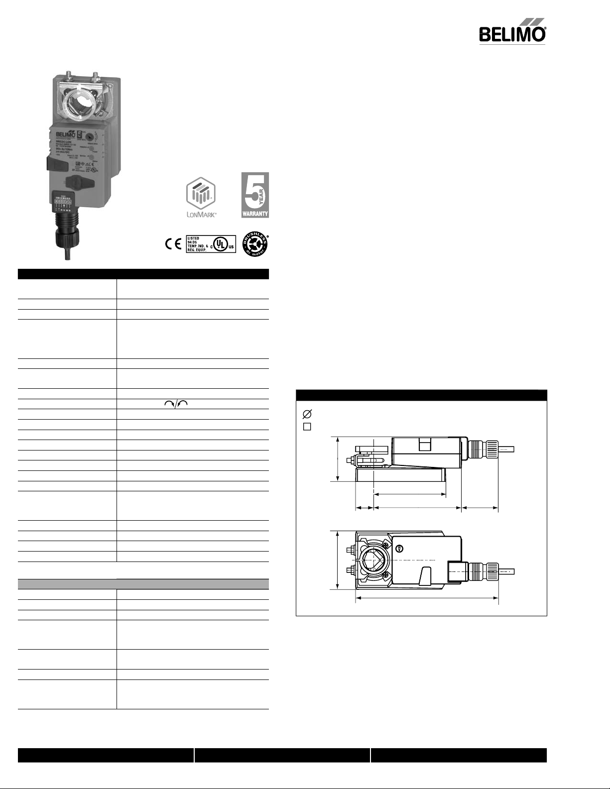
Dimensions (Inches [mm])
0.98"
[
25
]
4.74"
[
120.4
]
3
.
66
" [
93
]
2
"
[
5
0
.
8]
2.42"
[
61.4
]
3
.15"
[
80
]
7.7"
[
1
96
.
2]
1/2” to 1.05” [12.7 to 26.67]
2/5” to 1.05” [10 to 26.67]
D
14
2
Technical Data NMX24-LON
P
ower su
pp
l
y
24 VA
C
± 20% 50
/
60 H
z
24 VDC ± 10
%
P
ower consumptio
n
3.5 W
(
1.3 W
)
T
rans
f
ormer sizin
g
6 VA
(
Class 2 power source
)
E
lectrical connectio
n
18 GA
p
lenum rated cabl
e
1
/
2” conduit connecto
r
protected NEMA 2 (IP54)
3
f
t [1m
]
O
verload protectio
n
electronic throu
g
hout 0 to 95° rotation
An
g
le o
f
rotatio
n
max. 95°, ad
j
ustable with mechanical sto
p
e
l
ectron
i
ca
ll
y var
i
a
ble
T
orqu
e
90 in-lb [10 Nm]
Direction o
f
rotatio
n
reversible with switc
h
Posi
t
io
n
i
n
dica
t
ion
re
f
lective visual indicator
(
snap-on
)
Ma
n
ua
l
o
v
e
rri
de
external push butto
n
R
unning tim
e
150 seconds (de
f
ault
)
H
umidit
y
5 to 95% RH non condensin
g
(
EN 60730-1
)
Ambient tem
p
eratur
e
-22°F to 122°F
[
-30°C to 50°C
]
S
torage temperature -40°F to 176°F [-40°
C
to 80°
C
]
H
ousin
g
NEMA 2, IP54, UL enclosure t
yp
e 2
H
ousin
g
materia
l
UL94-5VA
A
gency
li
st
i
ngs
†
cULus acc. to UL 60730-1A
/
-2-14,
CAN/CSA E60730-1:02,
C
E acc. to 2004
/
108
/
EE
C
and 2006
/
95
/
E
C
No
i
se
l
e
v
el
<45dB
(
A
)
Servicin
g
maintenance
f
ree
Q
ualit
y
standar
d
I
SO
900
1
W
ei
g
ht 2.1 lbs
[
0.95 k
g]
†
Rated Impulse Voltage 800V, Type of action 1, Control Pollution Degree 3
.
Lo
n
Wo
r
ks
®
Ce
rtifi
ed
accordin
g
to Lo
n
M
ARK
®
3
.
3
P
r
ocessor
N
eu
r
o
n
3
12
0
T
ransceive
r
FTT-10A, com
p
atible with LPT-10
F
unctional
p
ro
f
il
e
accordin
g
to Lo
n
M
ARK
®
Dam
p
e
r
actuator o
bj
ect #8110
open loop sensor object #1
L
N
S
plug-in for actuator
/
sensor can be run with any LN
S
based integratio
n
tool (min. for LNS 3.x
)
Se
rvi
ce
bu
tt
o
n
a
n
d
s
t
a
t
us
LED accor
di
n
g
to
L
o
n
MARK
®
g
u
id
e
li
ne
s
C
onductors, cables conductor lengths, cable speci
f
ications and
topology of the LonWorks
®
network according to
th
e
E
c
h
e
l
o
n
®
d
ir
ec
tiv
es
L
on
W
or
k
s an
d
L
on
MARK
©
2007-2009 LonMark Internationa
l
M
40024 - 05/10 - Subject to change. © Belimo Aircontrols (USA), Inc.
800-543-9038 USA 866-805-7089 CANADA 203-791-8396 LATIN AMERICA
2
7
6
Accessories
K
-
NA
Reversible
C
lamp
ZG-10
0
Universal Mounting Bracke
t
ZG-101 Universal Mounting Bracke
t
Z
G
-1
03
Universal Mounting Bracke
t
Z
G
-104 Universal Mounting Bracke
t
Z
G
-NM
A
C
rank arm Ada
p
tor Kit
AV
8
-2
5
U
niv
e
r
sa
l
S
h
a
ft Ext
e
n
s
i
on
Z
G
-NM
S
A-1
S
haft Adaptor
ZS-10
0
Weather Shield - Stee
l
Z
S
-15
0
Weather
S
hield - Polycarbonat
e
Tool-0
6
8 mm & 10 mm Wrench
S
1A
,
S
2
A
A
uxiliary
S
witch (es)
P
37
0
S
haft Mount Auxiliar
y
Switch
P
…
A
F
eedbac
k P
o
t
e
nti
o
m
e
t
e
r
s
SGA24 Min positioners in NEMA 4 housing
SG
F24 Min positioners for flush panel mountin
g
ADS-100
A
nalog to Digital Switch
N
SV24 U
S
Battery Back-Up Modul
e
ZG-X4
0
Trans
f
orme
r
N
O
TE: When usin
g
NMX24-LON actuators, only use accessories listed on this pa
g
e
.
Typical Specification
P
roportional control damper actuators shall be electronic direct-coupled type, which
require no crank arm and linkage and be capable o
f
direct mounting to a sha
f
t up to
1.05” diameter. Actuators shall have brushless DC motor technolo
g
y and be protected
f
rom overload at all an
g
les o
f
rotation. Actuators shall have reversin
g
switch and
m
anual override on the cover. Run time shall be constant and independent o
f
torque.
Actuators shall be cULus listed, have a 5-year warranty, and be manu
f
actured under
I
SO 9001 International Qualit
y
Control Standards. Actuators shall be as manufactured
b
y
Belimo
.
Wiring Diagrams
V
Possible connection o
f
a
voltmeter for checkin
g
the position feedback U
.
567321
MFT
LON
LON
T
~
+
–
T
~
+
–
V
S
chema
_
L
O
N
_
0
1
C
onnection without
S
ensor
NMX24-L
ON
Lo
nW
o
rk
s
®
, Non-
S
prin
g
Return, 24
V
567321
MFT
LON
LON
T
~
+
–
T
~
+
–
S
ensor scalin
g
:
T
he sensors can be scaled with the sensor plu
g
-in
(
sensor table
).
Sensor Temperature range Resistance range Resolution
Ni
100
0
–
28 ... +98°
C
8
50 ... 1600
Ω
1
Ω
PT
100
0
–35 ... +155°
C
8
50 ... 1600
Ω
1
Ω
NT
C
–1
0
... +1
60
°
C
(
dependin
g
on type
)
2
00
...
60
k
Ω
1
Ω
S
chema_L
O
N_02
Connection with Passive Sensor, e.g. Pt1000, Ni1000, NT
C
567321
MFT
LON
LON
T
~
+
–
T
~
+
–
Re
q
uirements fo
r
sw
i
tch
i
n
g
contact
:
The switching contact must be
able to accuratel
y
switch a cur-
r
e
nt
o
f 1
6
mA
@
24 V
.
S
chema_L
O
N_03
C
onnection with
S
witchin
g
C
ontact, e.
g
.
Δ
p
-mon
i
tor
567321
MFT
LON
LON
T
~
+
–
T
~
+
–
Poss
i
ble
i
nput volta
g
e ran
g
e:
0 ... 32 V
(
resolution 30 mV
)
S
ensor scalin
g
:
Th
e
se
n
so
r
s
ca
n
be
sca
l
ed
with th
e
s
ensor plug-in (sensor table)
S
chema_L
O
N_0
4
Connection with Active Sensor, e.
g
. 0...10 V @ 0...5
0
°
C
M40024 - 05/10 - Sub
j
ect to chan
g
e. © Belimo Aircontrols
(
USA
)
, Inc.
800-543-9038 USA 866-805-7089 CANADA 203-791-8396 LATIN AMERICA
27
7
NMX24-L
ON
Lo
n
Wo
r
ks
®
,
Non-Sprin
g
Return, 24 V
N
ode ob
j
ect #
0
T
he node ob
j
ect contains the ob
j
ect status and ob
j
ect request
f
unctions
.
n
viRequest SNVT_obj_reques
t
I
nput variable
f
or requesting the status o
f
a particular object in the node
.
n
voStatus SNVT_ob
j
_statu
s
O
utput variable that outputs the current status of a particular object in the node
.
n
voFileDirector
y
SNVT_address
O
utput variable that shows information in the address ran
g
e of the Neuron chip
.
D
amper actuator object #811
0
T
he actuator ob
j
ect is used to map the functions of the MP actuators to the
LO
NW
O
RK
S®
n
e
tw
o
rk.
n
viRelSt
p
t SNVT_lev_
p
ercen
t
T
he nominal position is assigned to the actuator via this input variable. This variable is
n
ormall
y
linked to the out
p
ut variable of an HVA
C
controller
.
n
viActuateState SNVT
_
switc
h
A
preset position is assi
g
ned to the actuator via this input variable. Note on priority:
T
he last variable that was active, either nviActuatorState or nviRelSt
p
t, has
p
riorit
y
.
n
viManOvrd SNVT_hvac_overi
d
Th
ese
i
nput var
i
a
bl
es can
b
e use
d
to manua
ll
y overr
id
e t
h
e actuator
i
nto a part
i
cu
l
ar
p
os
i
t
i
on
.
n
voActualValue SNVT_lev_percen
t
T
his output variable shows the current actual position o
f
the actuator and can be used
f
or control circuit
f
eedback or
f
or displayin
g
positions
.
n
voAbsAngle
S
NVT_angle_deg
T
his output variable shows the current angle o
f
rotation o
f
the actuator
o
r the valve and can be used to display the position or
f
or service purposes.
n
voAbsAirFlow SNVT_flow
T
his output variable is inactive with the SR24ALON-5 rotary actuator and shows a
c
onstant value of 65535 (this variable is only active in conjunction with L
O
N-capable
V
AV controllers)
.
O
pen loop sensor object #
1
A
sensor can be connected to the rotary actuator. A passive resistance sensor
(
e.
g
.
N
i1000
)
, an active sensor
(
output 0 ... 32 V
)
or a switch
(
on/off
)
can be connected. The
o
pen loop sensor ob
j
ect transfers the measured sensor values to the LONWORKS®
n
etwor
k.
n
voSensorValue SNVT_xx
x
T
his output variable shows the current sensor value. Dependin
g
on the connected
s
ensor, the output variable can be con
f
igured via the sensor plug-in and speci
f
ically
a
da
p
ted to the s
y
stem
.
The SNVT_... can be configured as:
S
NVT_tem
p
_
p
S
NVT_lev_
p
ercent
S
NVT_lux
S
NVT_temp
S
NVT_abs_humid
S
NVT_press_p
S
NVT
_
switch
S
NVT_enthalp
y
S
NVT
_
smo
_
obscur
S
NVT
_
flow
S
NVT_ppm
S
NVT_power
S
NVT_flow_p
S
NVT_rpm
S
NVT_elec_kw
h
Notes
D
etailed in
f
ormation on the
f
unctional pro
fi
les can be
f
ound on the website o
f
LonMARK
®
K
K
(
www.
l
onmar
k
.org
)
.
Functional Profile according to LonMARK
®
K
K
T
he L
O
N-ca
p
able dam
p
er actuator is certified b
y
LonMARK
®
. Th
e
ac
t
ua
t
o
r
fu
n
c
ti
o
n
s
are supp
li
e
d
w
i
t
h
t
h
e
L
on
W
or
ks
®
networ
k
as stan
d
ar
di
ze
d
networ
k
var
i
a
bl
es
according to LonMARK
®
. The Node Object #0, the Damper Actuator Object #8110
and the Open Loop SensorObject #1 are implemented in the actuator.
M
40024 - 05/10 - Subject to change. © Belimo Aircontrols (USA), Inc.
800-543-9038 USA 866-805-7089 CANADA 203-791-8396 LATIN AMERICA
2
7
8
NMX24-L
ON
Lo
nW
o
rk
s
®
, Non-
S
prin
g
Return, 24
V
1
Direction o
f
rotation switc
h
S
witchin
g
ove
r
Direction o
f
rotation chan
g
es
2
Pushbutton and green LED d
i
spla
y
O
f
f
No voltage supply or mal
f
unction
Green
,
on Operatio
n
Press butto
n
S
witches on angle of rotation adaption followed
b
y
standard o
p
eratio
n
3
Service button for commissioning LONWORK
S
®
and
y
ellow LED dis
p
la
y
for the LON statu
s
O
f
f
The SR24ALON-5 rotar
y
actuator is connected
and ready for operation in the
L
O
NW
O
RK
S®
network.
Y
e
ll
ow
,
o
n
No application software is loaded in the
SR24ALON-5
.
Yellow, flashin
g
(flashing interval 2 seconds)
The SR24ALON-5 is read
y
for o
p
eration but not
integrated in the L
O
NW
O
RK
S
®
networ
k
(
unconfi
g
ured
).
O
ther flashing codes A fault is present in the
S
R24AL
O
N-5
.
Press butto
n
Service Pin Messa
g
e is sent to the
LONWORK
S
®
n
etwork
.
4
Gear disen
g
a
g
ement switc
h
Pr
ess
bu
tt
on
Gear disen
g
a
g
ed, motor stops, manual operation
poss
ible
R
e
l
ease
b
utto
n
Gear engaged, synchronisation starts, followed
b
y stan
d
ar
d
operat
i
o
n
5
Service plu
g
For connectin
g
MFT parameterizin
g
and service tool
s
1
2
3
4
5
M40024 - 05/10 - Sub
j
ect to chan
g
e. © Belimo Aircontrols
(
USA
)
, Inc.

Other Belimo Controllers manuals

Belimo AF24-LIN US User manual

Belimo

Belimo AF24-LIN US User manual

Belimo SY U24-SR Series Quick start guide

Belimo

Belimo SY U24-SR Series Quick start guide

Belimo ZEV Instruction manual

Belimo

Belimo ZEV Instruction manual

Belimo FGVL Series User manual

Belimo

Belimo FGVL Series User manual

Belimo NFBUP User manual

Belimo

Belimo NFBUP User manual

Belimo LMB24-SR User manual

Belimo

Belimo LMB24-SR User manual

Belimo NIMVR C Series User manual

Belimo

Belimo NIMVR C Series User manual

Belimo TR24-SR User manual

Belimo

Belimo TR24-SR User manual

Belimo LMQB24-MFT Instruction manual

Belimo

Belimo LMQB24-MFT Instruction manual

Belimo LRB24-3 User manual

Belimo

Belimo LRB24-3 User manual

Belimo LF-2 Series User manual

Belimo

Belimo LF-2 Series User manual

Belimo ZSN-BF User manual

Belimo

Belimo ZSN-BF User manual

Belimo AFX24LON User manual

Belimo

Belimo AFX24LON User manual

Belimo AM230-SR User manual

Belimo

Belimo AM230-SR User manual

Belimo CR24 Series User manual

Belimo

Belimo CR24 Series User manual

Belimo LRB24-MFT User manual

Belimo

Belimo LRB24-MFT User manual

Belimo NM24P Instruction Manual

Belimo

Belimo NM24P Instruction Manual

Belimo ARX24-3-5 User manual

Belimo

Belimo ARX24-3-5 User manual

Belimo LRX24-SR User manual

Belimo

Belimo LRX24-SR User manual

Belimo LRB24-SR-T Manual

Belimo

Belimo LRB24-SR-T Manual

Belimo SF24A-MP Instruction Manual

Belimo

Belimo SF24A-MP Instruction Manual

Belimo AFRB24-MFT N4H User manual

Belimo

Belimo AFRB24-MFT N4H User manual

Belimo FSAF24-SR US User manual

Belimo

Belimo FSAF24-SR US User manual

Belimo AVK230A-3 Instruction Manual

Belimo

Belimo AVK230A-3 Instruction Manual

Popular Controllers manuals by other brands

Hydrofarm Autopilot APC8200 user manual

Hydrofarm

Hydrofarm Autopilot APC8200 user manual

Flowserve Valtek Mark Safety guide

Flowserve

Flowserve Valtek Mark Safety guide

Toho Electronics TTM-339 Operation manual

Toho Electronics

Toho Electronics TTM-339 Operation manual

AirCom R364-S operating manual

AirCom

AirCom R364-S operating manual

Delta Electronics AH500 Operation manual

Delta Electronics

Delta Electronics AH500 Operation manual

Distech Controls DA-016N024PX installation instructions

Distech Controls

Distech Controls DA-016N024PX installation instructions

LEGRAND 0 484 22 manual

LEGRAND

LEGRAND 0 484 22 manual

Circuitron TC-1 quick start guide

Circuitron

Circuitron TC-1 quick start guide

Datapath VSN450 quick start guide

Datapath

Datapath VSN450 quick start guide

PTC Sigma Tile quick start guide

PTC

PTC Sigma Tile quick start guide

Woodward APECS DPG-2101-001 user manual

Woodward

Woodward APECS DPG-2101-001 user manual

Castle Creations Pixie-7 quick start guide

Castle Creations

Castle Creations Pixie-7 quick start guide

THORLABS PDXC ORIC user guide

THORLABS

THORLABS PDXC ORIC user guide

URC WC-1 owner's manual

URC

URC WC-1 owner's manual

Lance Design TDC-100B Preliminary installation and operation manual

Lance Design

Lance Design TDC-100B Preliminary installation and operation manual

Siemens GEB-1E Series Mounting instructions

Siemens

Siemens GEB-1E Series Mounting instructions

TKR Group HP 90 HK instruction manual

TKR Group

TKR Group HP 90 HK instruction manual

CIAT 1-PH HEE BOX Control manual

CIAT

CIAT 1-PH HEE BOX Control manual

manuals.online logo
manuals.online logoBrands
  • About & Mission
  • Contact us
  • Privacy Policy
  • Terms and Conditions

Copyright 2025 Manuals.Online. All Rights Reserved.