manuals.online logo
Brands
  1. Home
  2. •
  3. Brands
  4. •
  5. Belimo
  6. •
  7. Controllers
  8. •
  9. Belimo ZEV Instruction manual

Belimo ZEV Instruction manual

Technical data sheet ZEV
www.belimo.com T4-ZEV • en • v1.3 • 09.2007 • Subject to changes 1 / 4
Technical data
Electrical data Nominal voltage AC 24 V, 50/60 Hz, DC 24 V
Power supply range AC 19.2 ... 28.8 V, DC 21.6 ... 26.4 V
Power consumption 1 W
PP communication DC 1.0/12.5 V max. DC 15 V
bidirectional 1200 baud
Connection Screw terminals for 2 x 1.5 mm2
Connection cable separate obtainable, see «Accessories» on page 4
Safety Protection class III Safety extra-low voltage
Degree of protection IP42
EMC CE according to 89/336/EEC
Ambient temperature range 0 ... +50 °C
Non-operating temperature range -20 ... +80 °C
Moisture test According to EN 60730-1
Dimensions / weight Dimensions See «Dimensions» on page 3
Weight Approx. 500 g
Adjustment tool with PP interface
for VAV controller
• Nominal voltage AC/DC 24 V
• Peer-to-peer connection
to VAV controller via
– U/PP connection
– Service socket
– Connection terminals
1) Mode setting 0 ... 10 V / 2 ... 10 V
2) See mode setting
3) Devices manufactured before 8/2006 need a modified scale sticker
Brief description
Applications The ZEV adjustment tool enables the operating volumetric flow settings in VAV and CAV sys-
tems with conventional control to be adjusted on site. It is not suitable for systems with an MP
bus connection.
Can be used with
– NMV-D2, VRD2, VRD2-L 1)
– LMV-D2M, NMV-D2M 2)
– LMV-D2-MP, NMV-D2-MP, SMV-D2-MP 2) 3)
– LHV-D2M 2) 3)
Connection The ZEV is connected to the VAV-Compact using the PP (peer-to-peer) interface of the VAV
controller.
As well as using the service socket on the VAV-Compact, it is also possible to connect the ZEV
to easily accessible connection points such as the service plug on the CR24-B room tempera-
ture controller or on the terminals in the control cabinet. This means there is no need for direct
access to the VAV controller.
Supply The 24 V supply to the ZEV comes via the service socket of the VAV, CR24 controller or from a
local 24 V supply, e.g. connection terminals of the VAV controller.
VAV-Compact The VAV-Compact devices do not have any operating elements such as switches or setpoint
potentiometers. If necessary, the operating parameters are set using the ZEV or another adjust-
ment tool, e.g. the PC-Tool with additional functions such as trend, etc.
VAV-Universal In the VRD2(-L), it is possible to set the mode appropriately for the selected 0…10 V or 2...10 V
room temperature controller.
Products no longer available
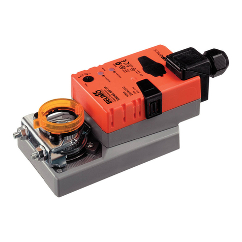
ZEV VAV adjustment tool
2 / 4 T4-ZEV • en • v1.3 • 09.2007 • Subject to changes www.belimo.com
Electrical installation
Wiring diagrams
~T
T
551
U/PP
AC 24 V
T
~
1234
– + DC 24 V
T
PP
The ZEV is connected to connections 1 and 5 of the correspond-
ing controller. The ZEV supply (AC/DC 24 V) comes directly from
connection 2.
When the system is being wired up, it is advantageous for the
actual value signal U5 (terminal 5) of the VAV controller to be fed
back to the room temperature controller or into the control cabinet.
Communication is via a peer-to-peer connection (PP).
Connection options Connection via service socket (Cable see «Accessories» on page 4)
1
2
3
5
Y
U
~
T
51 2
AC 24 V
T
~
– + DC 24 V
51 2
LMV-D2-MP / NMV-D2-MP / SMV-D2-MP
LHV-D2-MP
CR24-B..
Connection via connection terminals
1
2
3
5
Y
U
~
T
51 2
AC 24 V
T
~
– + DC 24 V
LMV-D2M / NMV-D2
LMV-D2-MP / NMV-D2-MP / SMV-D2-MP
LHV-D2-MP
VRD2 / VRD2-L
Note
Connection via safety transformer!
!
– Device terminals / connection socket
– Switch cabinet terminals
ZK5-GEN ZKS-VAV
Service socket
Note
• When an operating device (e.g. ZEV) is con-
nected via the U/-PP connection (terminal 5) of
the VAV controller, the voltage signal of output
U5 does not correspond to the current actual
value signal.
When using the service socket of an LMV-D2-
MP, NMV-D2-MP or SMV-D2-MP, the U5 signal
is not impaired.
• The maximum communication level is DC 15 V.
To prevent damage to third-party equipment, it
may have to be disconnected from terminal 5
under certain circumstances – for the duration of
communication.
Safety notes
!
• The device is not allowed to be used outside the specified field of application, especially in
aircraft or in any other airborne means of transport.
• Only for Belimo VAV devices with 24 V safety extra-low voltage.
blue
turquise
violet
black
red
white
Products no longer available
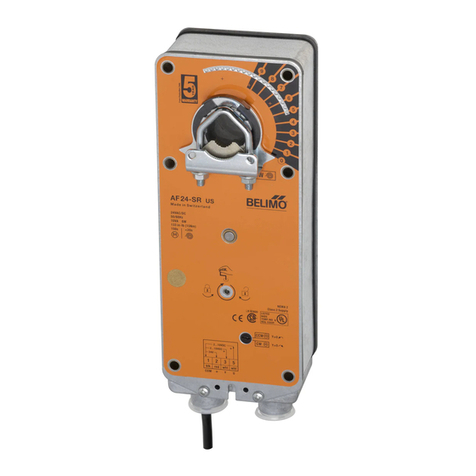
ZEV VAV adjustment tool
www.belimo.com T4-ZEV • en • v1.3 • 09.2007 • Subject to changes 3 / 4
Operation
Structure A B
C D E
AOperating volumetric flow min
BOperating volumetric flow max
CMode setting for reference and volumetric flow actual value signal
DFunctional check of control loop nominal/actual value comparison
EReset min.-/ max. setting to original OEM values
Operation Query Programming
? 
MIN

MAX
set
? 
MIN

MAX
LED
LED
LED
LED
? 
MIN

MAX
set
? 
MIN

MAX
LED
LED
LED
LED
for VRD2(-L), NMV-D2,
LMV-D2M, NMV-D2M
Turn the rotary button slowly until
the check LED lights up.
– Flashing LED:
Value in VAV controller is lower
– LED dark:
Value in VAV controller is higher
Set the value at the corresponding rotary button:
Press and hold the «Set» button for 2 seconds. The
write procedure is acknowledge by the LED lighting
up (see application table on page 4).
for LMV-D2-MP, NMV-D2-MP,
SMV-D2-MP
Turn the rotary button slowly until
the check LED flashes.
3 - 4s
LED Vmin
LED Vmax
– The following flashing sequence indica-
tes that the value in the VAV controller is
greater.
3 - 4s
LED Vmin
LED Vmax
Set the value with the corresponding rotary button:
Press the «Set» button repeatedly until the following
flashing sequence indicates that the value has been
accepted.
3 - 4s
LED Vmin
LED Vmax
– LED dark:
Value in VAV controller is higher.
Functional checkVAV control loop Green LED lights up
Green LED flashes
– Dark
– Bright
→ Actual value same as nominal value
→ Actual value not same as nominal value
→ Volumetric flow not reached
→ Volumetric flow too high
Note
ZEV devices manufactured before 8/2006 need a
modified scale sticker. Please contact your Belimo
branch.
Yellow LED lights up
LED dark
Legend
Products no longer available
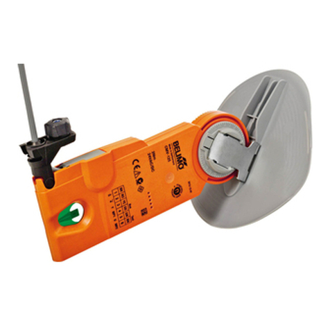
ZEV VAV adjustment tool
4 / 4 T4-ZEV • en • v1.3 • 09.2007 • Subject to changes www.belimo.com
1) See product information for VAV-Compact and VAV-Universal
2) Lowest setting depends on the creep flow suppression. See VAV product information documents or refer to data from the VAV manufacturer.
3) ZEV devices (manufactured before 8/2006) need a modified scale sticker. Please contact your Belimo branch.
4) The "Constant" option is irrelevant for the current VRD2, L/NMV-D2M and L/N/SMV-D2-MP versions.
5) If the LED constantly displays low-power "dark" flashes (> 3 min), this means the actuator is most probably at a limit position.
Application with different VAV versions
Version LMV-D2-MP
NMV-D2-MP
SMV-D2-MP
Note
Technical data 1) Nominal voltage AC 24 V, 50/60 Hz
Connection of operating devices
min. setting Range
max. setting Range 30 ... 100% of nom
Mode Range Constant 4) / 2 ... 10 V / 0 ... 10 V
Feedback LED «Mode» LED lights up The set mode is not displayed on the LED but the
write command 5) is performed correctly
Reset operating volumetric flow settingmin./max.
to original factory setting
No function Reset to (OEM) factory setting
Functional check w = x Green LED lights up
Control loop w ≠ x Green LED flashes
Communication Normal LED function Data transmission is
displayed by brief flash-
es of the three LEDs 5)
Accessories
Type Use
Cable ZK5-GEN for new generation VAV-Compact, LMV-D2-MP, NMV-D2-MP, SMV-D2-MP, LHV-D2-MP
ZKS-VAV for LMV-D2M, NMV-D2M, CR24-A.., CR24-B..
Dimensions [mm]
Dimensional diagrams
4.5
130
140
153
45
43
88
5
54
VRD2
VRD2-L
NMV-D2 LMV-D2M
NMV-D2M
LMV-D2-MP
NMV-D2-MP
SMV-D2-MP
Current device Phased out by NMV-
D2M in 2000
Phased out by NMV-D2-
MP in 2006
Current device
Terminals Terminals Terminals, socket Terminals, socket
0 2) ... 100% of max 0 2) ... 100% of nom 3)
30 ... 100% of nom
Constant 4) / 2 ... 10 V / 0 ... 10 V
«Mode» LED lights up
The set mode is not displayed on the LED but the
write command
5)
is performed correctly
No function Reset to (OEM) factory setting
Green LED lights up
Green LED flashes 5)
Normal LED function Data transmission
is displayed by brief
flashes of the three
LEDs
Products no longer available
Other Belimo Controllers manuals

Belimo LF24 US User manual

Belimo

Belimo LF24 US User manual

Belimo SM24A-S Instruction Manual

Belimo

Belimo SM24A-S Instruction Manual

Belimo SMQ24G-SR Instruction Manual

Belimo

Belimo SMQ24G-SR Instruction Manual

Belimo LM Series User manual

Belimo

Belimo LM Series User manual

Belimo CR24 Series User manual

Belimo

Belimo CR24 Series User manual

Belimo LM24A-SX-F Instruction Manual

Belimo

Belimo LM24A-SX-F Instruction Manual

Belimo LMB24-3 Series Owner's manual

Belimo

Belimo LMB24-3 Series Owner's manual

Belimo AVK230A-3 Instruction Manual

Belimo

Belimo AVK230A-3 Instruction Manual

Belimo NMV-D3-RE2-SET User manual

Belimo

Belimo NMV-D3-RE2-SET User manual

Belimo LRQ24A User manual

Belimo

Belimo LRQ24A User manual

Belimo NF24A-SR-S2 Instruction Manual

Belimo

Belimo NF24A-SR-S2 Instruction Manual

Belimo TRANE TTF Series Guide

Belimo

Belimo TRANE TTF Series Guide

Belimo SF24A-MP Instruction Manual

Belimo

Belimo SF24A-MP Instruction Manual

Belimo CR24 Series User manual

Belimo

Belimo CR24 Series User manual

Belimo LMQB24-1 User manual

Belimo

Belimo LMQB24-1 User manual

Belimo SY U24-SR Series Quick start guide

Belimo

Belimo SY U24-SR Series Quick start guide

Belimo LRX User manual

Belimo

Belimo LRX User manual

Belimo PRCA-S2-T Instruction Manual

Belimo

Belimo PRCA-S2-T Instruction Manual

Belimo AFB Series User manual

Belimo

Belimo AFB Series User manual

Belimo LMQB24-MFT Instruction manual

Belimo

Belimo LMQB24-MFT Instruction manual

Belimo SY-3-T-TS Series Quick start guide

Belimo

Belimo SY-3-T-TS Series Quick start guide

Belimo NIMVR C Series User manual

Belimo

Belimo NIMVR C Series User manual

Belimo LF24-SR US User manual

Belimo

Belimo LF24-SR US User manual

Belimo AVK230A-3 User manual

Belimo

Belimo AVK230A-3 User manual

Popular Controllers manuals by other brands

Blueprint HUB-4 instructions

Blueprint

Blueprint HUB-4 instructions

Nordson EFD ValveMate 7140 operating manual

Nordson EFD

Nordson EFD ValveMate 7140 operating manual

GE ARITECH FP400 Series user guide

GE

GE ARITECH FP400 Series user guide

Barco ScreenPRO II quick start guide

Barco

Barco ScreenPRO II quick start guide

Sices GC310 user manual

Sices

Sices GC310 user manual

Intel 4 Series Thermal/Mechanical Design Guidelines

Intel

Intel 4 Series Thermal/Mechanical Design Guidelines

AQ M-TECH D72 manual

AQ M-TECH

AQ M-TECH D72 manual

Savant SmartControl SSC-W003I Quick reference guide

Savant

Savant SmartControl SSC-W003I Quick reference guide

WABCO smatrboard user manual

WABCO

WABCO smatrboard user manual

Kenwood KOS-A210 instruction manual

Kenwood

Kenwood KOS-A210 instruction manual

Hirata Corporation HNC-544 user guide

Hirata Corporation

Hirata Corporation HNC-544 user guide

DFE WebHandler 3 instruction manual

DFE

DFE WebHandler 3 instruction manual

Metso Quadra-Powr II Installation maintenance and operating instructions

Metso

Metso Quadra-Powr II Installation maintenance and operating instructions

IPS Controllers M920CA owner's manual

IPS Controllers

IPS Controllers M920CA owner's manual

Gerreka KM 600S instruction manual

Gerreka

Gerreka KM 600S instruction manual

ICP DAS USA LinPAC-5000 quick start

ICP DAS USA

ICP DAS USA LinPAC-5000 quick start

Basler AVC634A-12 Operation manual

Basler

Basler AVC634A-12 Operation manual

Ekinex EK-HA1-TP manual

Ekinex

Ekinex EK-HA1-TP manual

manuals.online logo
manuals.online logoBrands
  • About & Mission
  • Contact us
  • Privacy Policy
  • Terms and Conditions

Copyright 2025 Manuals.Online. All Rights Reserved.