manuals.online logo
Brands
  1. Home
  2. •
  3. Brands
  4. •
  5. Belimo
  6. •
  7. Controllers
  8. •
  9. Belimo T24-DM1 User manual

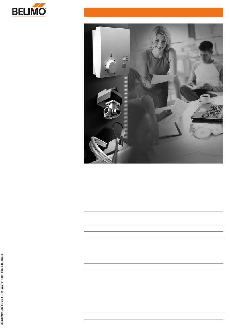
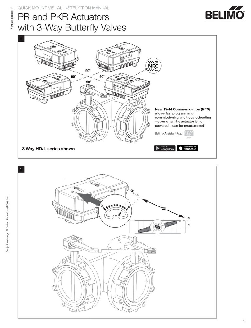
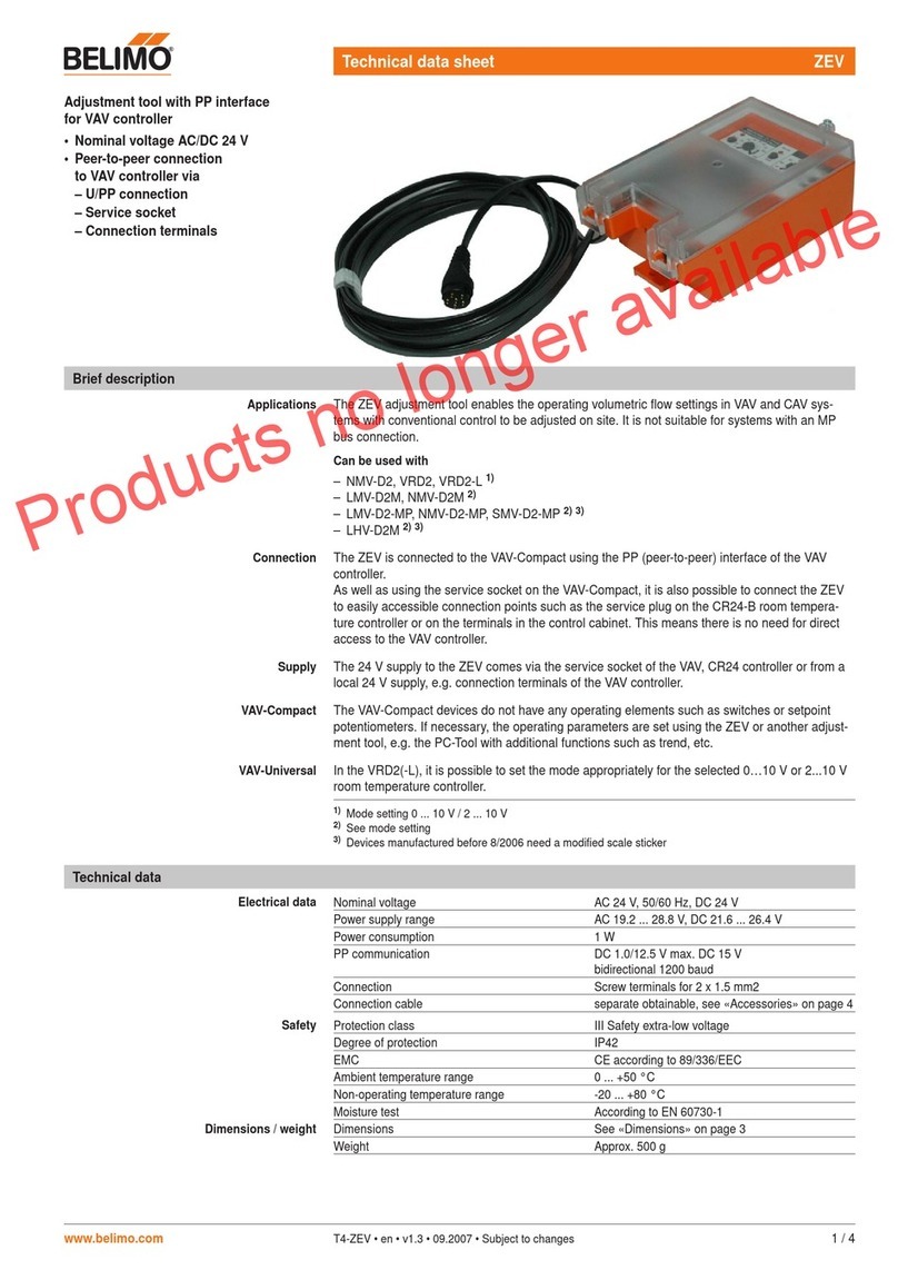
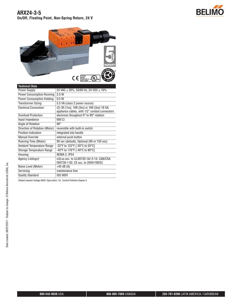
Belimo T24-DM1 User manual

86 mm
86 mm
28.5mm
60 mm
V1.5 04. 2014 · Subject to modification
1
T24-DM1 LCD Temperature Controller
Overview of product
LCD temperature controller T24-DM1 provides the foundation for modern
single room concepts.
Features
- LCD with white backlight
- Proportional output(s), DC 0...10V or 2...10V
- Adjustable P-band, I-time and setpoint range
- Display selection
- Unoccupancy mode
- Memory function after power failure
- Suits 2-pipe(T24-DM1) system
- External sensor TG-M10000(probe type) or TG-M10002(duct type)(optional)
Technical data
Installation and dimensions
Model
Norminal voltage
Power consumption
Output(s)
Built-in sensor
External sensor
Temperature range
Mode
Proportional band
Integral time
Display offset
Switching differential
Upper setpoint limit (USP)
Lower setpoint limit (LSP)
Unoccupancy setpoint range
Unoccupancy contact input
Connection
Ambient humidity
Body material
Weight
Dimensions (LxWxH)
Mounting
Degree of protection
Agency approval
T24-DM1(2-pipe)
AC 24V 50/60Hz (±15%, AC 20.4V...27.6V)
1VA@AC 24V
DC 0...10V or 2...10V by jumper setting
NTC thermistor, 10kΩ@25°C
TG-M10000(probe type) or TG-M10002(duct type)(optional)
Display : 0...40°C
Setpoint : 5...40°C, 0.5K per step
On / standby
Cooling / heating
1K...10K adjustable (factory default 5K)
0...300 seconds adjustable (factory default 60 seconds)
±2K adjustable (-2, -1, 0, +1, +2) (factory default 0)
1K
9...40°C, adjustable (factory default 40°C)
5...35°C, adjustable (factory default 5°C)
Cooling : 5...36°C (factory default 26°C)
Heating : 9...40°C (factory default 16°C)
Voltage free contact input
Screw terminals, maximum 1.0mm² or 18 AWG
Max. 90% RH, non-condensing
Self-extinguishing, molded ABS
120g
86 x 86 x 28.5mm
Wall mounted, holes separate 60mm vertically, 2x screws provided
IP30
CE mark compliant to EMC Directive
JP 1
JP 2
1. Enter setup menu Switch the unit to ‘standby’ mode, press and hold “ ”, then press“ - ” , hold “ - ” and release “ ”, keep
holding “ - ” for 10s until “ S-F ” appears.
2. Select sub-menu “ S-F ” or “ S-P ” After enter setup menu and “ S-F ” appears, press “ + “ or “ - ” to select “ S-F ” or “ S-P ”, confirm by “ ”.
3. Select function under sub-menu Under sub-menu, press “ ” key momentarily to select the functions sequentially.
4. Adjust parameters Press “ + ” or “ - ” to adjust parameter value.
5. Save changes and
go back to sub-menu selection
Press and hold “ ” , then press“ + ” , hold “ + ” and release “ ”, keep holding “ + ” for 1s.
Under sub-menu, press “ ” to exit.
6. Exit setup menu
7. Time out If there is no key operation for 30 seconds, new setting will not be stored and exit automatically.
V1.5 04. 2014 · Subject to modification
2
T24-DM1 LCD Temperature Controller
Setup menu
Jumper setting
Wiring diagrams
Notes
Caution
Sub-menu S-F
Firmware version
Temperature display
Selection for unoccupancy mode
Display selection
Restore factory setting
S
t
uA
c
rF
Display only
Display in °C only
To select uA1 or uA2
cAt = display ambient temperature
cSP = display setpoint value
rFC = current setting
rFS = restore factory setting
(factory default uA1)
(factory default cAt)
(factory default rFC)
Sub-menu S-P
Proportional band
Integral time
Upper setpoint limit
Lower setpoint limit
Unoccupancy setpoint range - cool
Unoccupancy setpoint range - heat
Display offset
A
I
U
L
C
H
n
Adjustable, 1...10K
Adjustable, 0...30 (1=10s)
Adjustable, 9...40°C
Adjustable, 5...36°C
Adjustable, 5...40°C
Adjustable, 5...36°C
Adjustable, -2,-1,0,+1,+2
(factory default 5K)
(factory default 6)
(factory default 40°C)
(factory default 5°C)
(factory default 26°C)
(factory default 16°C)
(factory default 0)
Open
Close
Use external sensor
Use built-in sensor (factory default)
Open
Close
DC 0...10V output
DC 2...10V output (factory default)
Terminals for sensor
4
3
2
1
Valve actuator
AC 24V
Com
0-10V
2
1
3
T24-DM1
Feedback
5
5
*2 & 4 are internally shorted
SR1
GND
OCU
External
sensor
Occupancy
contact
- 22 or 24 AWG twisted shielded pair double insulated cable is recommended as sensor cable and its length must not exceed 25m.
- Do not bundle and run power cable and sensor cable in the same conduit.
- When using external sensor, run the cable away from any electric motor or power cable.
- Remove JP1 whenever using external sensor.
- Unoccupancy contact CLOSE activates unoccupancy mode.
- Unit to be opened by accredited servicing agents only.
- Electronic control - Type 2.B action (micro-disconnection operation).
- Separate collection for electrical and electronic equipment.
JP2 JP1
t.
Menu noitpircseDnoitcnuF
Main Sub
S- F
System
function
selection
S
uA
rF
S- P
System
operating
parameter
setting
A
I
U
L
C
H
n
t
c
V1.5 04. 2014 · Subject to modification
3
T24-DM1/T24-DM2 LCD Temperature Controller
Setup menu - description
Error code
Error code will be displayed on LCD for following errors:
E-1 EEPROM read/write error
E-2 Temperature sensor open circuit
E-3 Temperature sensor short circuit
Remarks: If jumper JP1 is OPEN and external sensor is used, E-2 indicates external sensor may disconnected from terminals SR1 or GND.
Check external sensor connection and resistance value.
Fixed, °C
Appear once only after entering setup mode
uA1 = unoccupancy mode can be activated when thermostat is in operating
mode (factory default)
uA2 = unoccupancy mode can be activated when thermostat is in operating
mode or standby mode
cAt = display ambient temperature (factory default)
cSP = display setpoint value
rFC = Keep current settings (factory default)
rFS = Restore factory settings
Set proportional band from 1K to 10K, in 1K per step (factory default 5K).
Set integral time from 0 (0s) to 30 (300s) in numeric 1 (10s) per step (factory
default 6(60s))
Setting 0 means integral time turn off.
Set upper setpoint limit, adjustable between current lower setpoint limit and
40°C (factory default 40°C).
The program is set to always have a minimum separation of 4K maintained
between upper setpoint limit and lower setpoint limit.
Set lower setpoint limit, adjustable between current upper setpoint limit and 5°C
(factory default 5°C).
The program is set to always have a minimum separation of 4K maintained
between upper setpoint limit and lower setpoint limit.
Temperature unit
MCU firmware (software) version
Activation selection for unoccupancy
mode
Display selection
Restore factory settings
Proportional band
Integral time for PI control
Upper setpoint limit
Lower setpoint limit
Unoccupancy cooling setpoint
Unoccupancy heating setpoint
Offset adjustment of temperature display
(field calibration of measured ambient
temperature)
Appears once only after entering the setup mode
Set unoccupancy cooling setpoint, adjustable between current unoccupancy
heating setpoint and 40°C (factory default 26°C).
The program is set to always have a minimum separation of 4K maintained
between unoccupancy cooling sepoint and unoccupancy heating setpoint.
Set unoccupancy heating setpoint, adjustable between current unoccupancy
cooling setpoint and 5°C (factory default 16°C).
The program is set to always have a minimum separation of 4K maintained
between unoccupancy cooling sepoint and unoccupancy heating setpoint.
n 2 = temperature display plus 2 degrees
n 1 = temperature display plus 1 degree
n 0 = no offset (factory default)
n-1 = temperature display minus 1 degree
n-2 = temperature display minus 2 degrees
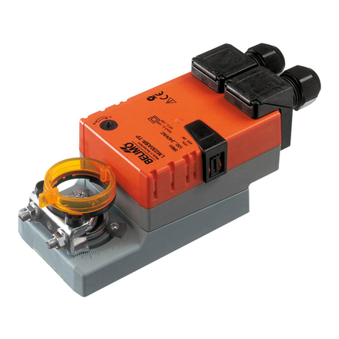
Other Belimo Controllers manuals

Belimo LM Series User manual
Belimo

Belimo LM Series User manual
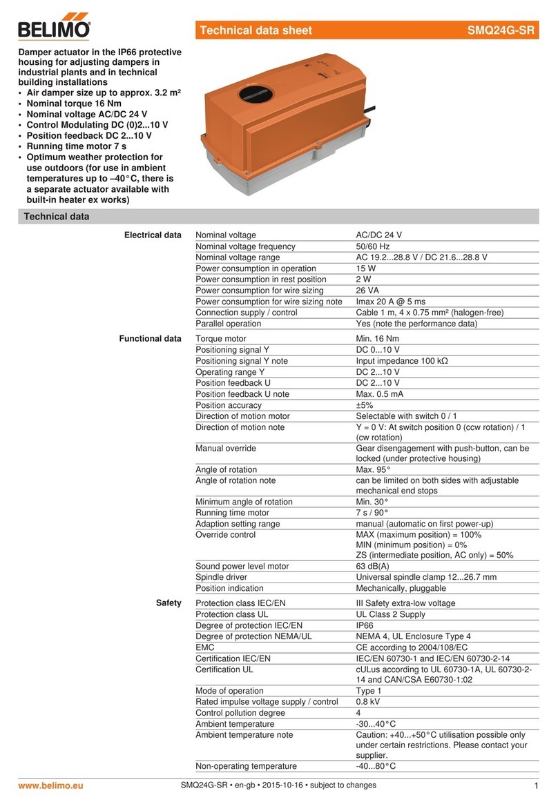
Belimo SMQ24G-SR Instruction Manual

Belimo

Belimo SMQ24G-SR Instruction Manual

Belimo PR User manual

Belimo

Belimo PR User manual

Belimo SRF230A-S2-5-O Instruction Manual

Belimo

Belimo SRF230A-S2-5-O Instruction Manual

Belimo AVK230A-3 Instruction Manual

Belimo

Belimo AVK230A-3 Instruction Manual

Belimo LF24 US User manual

Belimo

Belimo LF24 US User manual

Belimo EFB Series User manual

Belimo

Belimo EFB Series User manual

Belimo LonWorks NMX24-LON User manual

Belimo

Belimo LonWorks NMX24-LON User manual

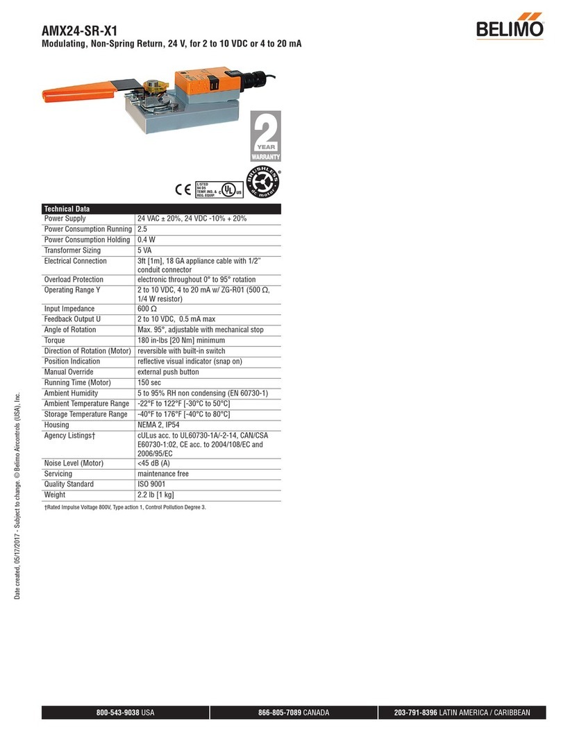
Belimo AMX24-SR-X1 User manual

Belimo

Belimo AMX24-SR-X1 User manual

Belimo AFB Series User manual

Belimo

Belimo AFB Series User manual

Belimo FS Series Use and care manual

Belimo

Belimo FS Series Use and care manual

Belimo LMQB24-MFT Instruction manual

Belimo

Belimo LMQB24-MFT Instruction manual

Belimo CR24 Series User manual

Belimo

Belimo CR24 Series User manual

Belimo AFB Series User manual

Belimo

Belimo AFB Series User manual

Belimo PKR Series User manual

Belimo

Belimo PKR Series User manual

Belimo ZEV Instruction manual

Belimo

Belimo ZEV Instruction manual

Belimo ARX24-3-5 User manual

Belimo

Belimo ARX24-3-5 User manual

Belimo NFBUP User manual

Belimo

Belimo NFBUP User manual

Belimo NMV-D3-RE2-SET User manual

Belimo

Belimo NMV-D3-RE2-SET User manual

Belimo NF24A-MOD Instruction Manual

Belimo

Belimo NF24A-MOD Instruction Manual

Belimo LF24-SR-E US User manual

Belimo

Belimo LF24-SR-E US User manual

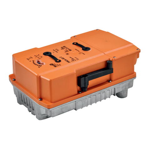
Belimo PRCA-S2-T Instruction Manual

Belimo

Belimo PRCA-S2-T Instruction Manual

Belimo SF24A-MP Instruction Manual

Belimo

Belimo SF24A-MP Instruction Manual

Belimo LRX User manual

Belimo

Belimo LRX User manual

Popular Controllers manuals by other brands

ABB ACS320 series user manual

ABB

ABB ACS320 series user manual

Asahi/America 19 Series user manual

Asahi/America

Asahi/America 19 Series user manual

ReActiveMicro MicroDrive Turbo owner's manual

ReActiveMicro

ReActiveMicro MicroDrive Turbo owner's manual

Bosch Rexroth IndraMotion MTX micro Easy setup

Bosch

Bosch Rexroth IndraMotion MTX micro Easy setup

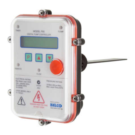
KELCO F60 Programming instructions

KELCO

KELCO F60 Programming instructions

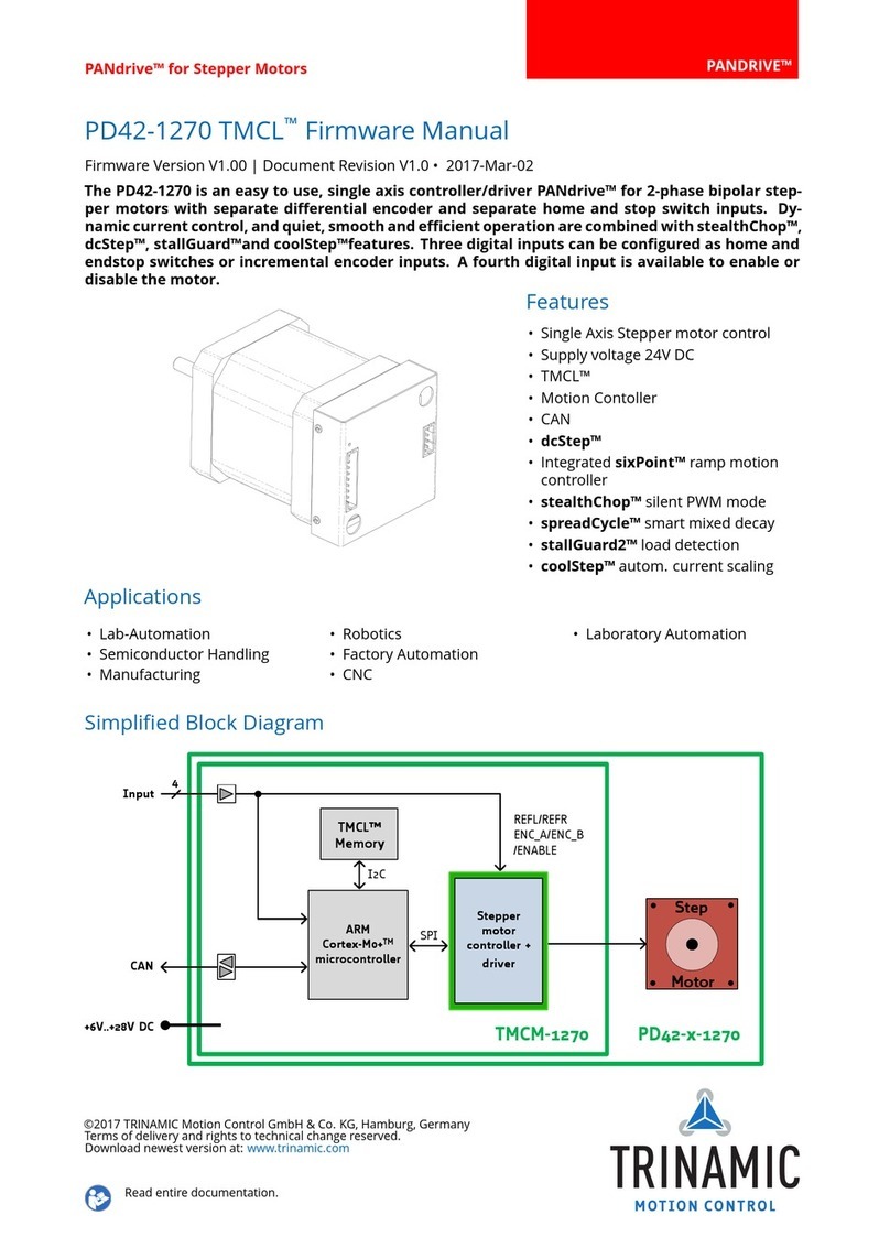
Pandrive PD42-1270 TMCL Firmware user manual

Pandrive

Pandrive PD42-1270 TMCL Firmware user manual

Conair Thermolater vacuTrac user guide

Conair

Conair Thermolater vacuTrac user guide

Danfoss ECL Comfort 110 quick guide

Danfoss

Danfoss ECL Comfort 110 quick guide

Traxon ecue LCE-mx Setup manual

Traxon

Traxon ecue LCE-mx Setup manual

Phocos 321666 user manual

Phocos

Phocos 321666 user manual

ISDT ESC70 user manual

ISDT

ISDT ESC70 user manual

CEBEK I-16 quick start guide

CEBEK

CEBEK I-16 quick start guide

Rutenbeck Control Plus IP4 installation instructions

Rutenbeck

Rutenbeck Control Plus IP4 installation instructions

Wahsega Labs Carina Installer's guide

Wahsega Labs

Wahsega Labs Carina Installer's guide

Tork DIN101B operating instructions

Tork

Tork DIN101B operating instructions

Johnson Controls VAP Series installation instructions

Johnson Controls

Johnson Controls VAP Series installation instructions

Calian SatService sat-nms ACU2-19V2 user manual

Calian

Calian SatService sat-nms ACU2-19V2 user manual

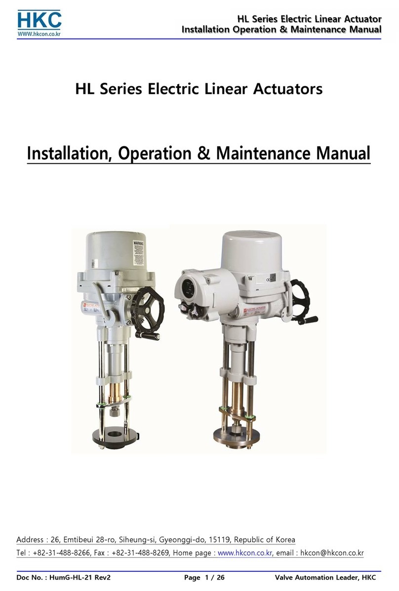
HKC HL Series Installation, operation & maintenance manual

HKC

HKC HL Series Installation, operation & maintenance manual

manuals.online logo
manuals.online logoBrands
  • About & Mission
  • Contact us
  • Privacy Policy
  • Terms and Conditions

Copyright 2025 Manuals.Online. All Rights Reserved.